
Path Planning and Control of a UAV Fleet in Bridge Management Systems
by
 , , , and
Antonio Bono
1 ,
,
Luigi D’Alfonso
1,
Giuseppe Fedele
1,
Anselmo Filice
1,* and
Enrico Natalizio
2,3
1
Department of Computer Science, Modeling, Electronics and Systems Engineering (DIMES), University of Calabria, 87036 Rende, Italy
2
LORIA Laboratoire Lorrain de Recherche en Informatique et Ses Applications, 54506 Vandoeouvre-les-Nancy, France
3
Autonomous Robotics Research Centre, Technology Innovation Institute (TII), Abu Dhabi P.O. Box 9639, United Arab Emirates
*
Author to whom correspondence should be addressed.
Remote Sens. 2022, 14(8), 1858; https://doi.org/10.3390/rs14081858
Submission received: 7 March 2022
/
Revised: 1 April 2022
/
Accepted: 6 April 2022
/
Published: 12 April 2022
(This article belongs to the Special Issue Robotics and AI for Infrastructure Inspection and Monitoring)
Abstract
:Traditional methodologies for precise inspection of bridges (pavement, beams, column cap, column, joints and inside box girder, etc.) with By-bridge equipment, Aerial Work Platform (AWP) or via ropes have several limits that can be overcome by using Unmanned Aerial Vehicles (UAVs). The constant development in this field allows us to go beyond the manual control and the use of a single UAV. In the context of inspection rules, this research provides new inputs to the multilevel approach used today and to the methods of structural inspection with drones. Today, UAV-based inspections are limited by manual and/or semi-automatic control with many restrictions on trajectory settings, especially for areas of difficult access with Global Navigation Satellite Systems (GNSS) denied that still require the intervention of a human operator. This work proposes the use of autonomous navigation with a fleet of UAVs for infrastructural inspections. Starting from a digital twin, a solution is provided to problems such as the definition of a set of reference trajectories and the design of a position controller. A workflow to integrate a generic Bridge Management System (BMS) with this type of approach is provided.
Keywords:
BMS; co-simulation; GNSS denied; BIM; BrIM; IFC; GIS; digital twin; NMPC; UAV; UAV swarm; path following; waypoint; cooperative surveillance; PnP; SHM; UKF1. Introduction
Bridge inspection and monitoring has gained more and more attention in the last decade due to the increased awareness of the perishability of construction materials. As a matter of fact, bridge failures are one of the worst infrastructural disasters both in term of life losses and economic implications [1]. One of the most fatal cases in recent years is the Morandi Bridge failure in Genoa, Italy. On 14 August 2018, during a torrential downpour, the 90 m high column No. 9 collapsed, along with the beams and the 200 m long road surface. The collapse killed 43 people, injured 11 and left 566 homeless [2].
The causes of such a phenomenon are several and are usually divided in two main categories: natural factors such as flood, scour, earthquakes, landslide and wind; and anthropic factors as imperfect design and construction methods, vehicle overloading, fire, terrorist attack and lack of inspection and maintenance. This last aspect is crucial according to [3], where statistics regarding failure of Chinese bridges between 2010 and 2019 have shown how lack of maintenance is one of the main causes of collapse.
The main drawback of infrastructural inspections is their cost and disruption caused to the travelling public. UAVs are one of the most promising low-cost alternatives for this task, with many benefits regarding the safety of operators, needed time and traffic management (an excellent cost–benefit analysis can be found in [3]). Just to give an idea of the amount of work that could benefit from these technologies, think of the Italian case: 180,000 km of main roads consisting of 30,000 bridges and 15,000 tunnels, with one of the highest incidences of infrastructure works per kilometer travelled [4].
Currently, most of the research related to automatic bridge inspection using UAVs focuses on missions performed by a single drone [5,6]. However, as is well known in the robotics community, single-robot systems are being outperformed by Multi Robot Systems (MRS) in several aspects:
- Parallelism: More agents can collaborate on the same task or on different ones.
- Robustness: If one robot breaks down or is attacked, the group, after a possible reconfiguration phase, can still perform the task. With a monolithic solution the breakage of the robot implies the failure of the mission.
- Simplicity: Usually, in MRS agents are less complex than the one used in monolithic solutions, where greater physical and computational abilities are required to perform the same task. This leads to lower probabilities of software/hardware bugs.
- Cost: The simplicity of the agents often makes building an MRS cheaper than building a single, more skilled robot that can solve the same tasks.
A UAV team in which each drone is equipped with a specific perception sensor can potentially have all the advantages listed above. In particular, the duration of the inspection can benefit significantly: if many different sensors are needed for structural analysis purposes, a team of UAVs can use them simultaneously while a single aircraft would be forced to perform multiple inspections.
These benefits come with costs, however. Among the main challenges that automating a multi-UAV inspection presents, in this work we focused on two:
- A fleet path planning that allows all components to perform the necessary analysis while simultaneously avoiding collisions with infrastructure and other aircraft.
- A control of UAVs that guarantees the tracking of the generated trajectories despite the unavoidable error on the actual position of the aircraft provided by GNSS-type localization systems.
The solution of such problems is but the first step towards real-world applications.
The programmatic management of bridge inspections, in fact, is managed through ad hoc information systems called Bridge Management Systems (BMSs). Such systems, however, are not yet configured for an MRS approach to the inspection [7,8].
In an attempt to answer to this shortcoming, our paper proposes a workflow that succeeds in integrating the latest techniques used by BMSs with an MRS-based inspection. In particular, we show how the digital representation of bridges through Building Information Modeling (BIM), together with georeferencing systems, is a very useful tool. Thanks to this information, the end-user will be able to easily set the waypoints of interest of the inspection using a digital twin representation of the bridge and later the real drones will be able to follow them without further measurements and checks in the field.
This paper proceeds in the following manner. Section 2 presents an overview on current BMSs and the most promising related technologies; Section 3 presents the proposed methodology that exploits the new possibilities offered by the digital twin representation of the bridges for planning and control of an autonomous multi-UAV inspection. Finally, Section 4 is devoted to conclusions and future directions.
2. Bridge Management Systems and Related Technologies
Today, most of the information useful for the management of bridge assets is provided by BMSs. Each road authority can thus process information related to bridge inspections and monitoring by its own BMS, usually developed together with external institutions such as universities, private individuals and investee companies [7]. The best-known Bridge Management Systems in Europe have been classified by [8] BaTMan (Sweden), BAUT (Austria), DANBRO (Denmark), KUBA (Switzerland), SIB-Bauwerke (Germany) and SMIS (United Kingdom). In Italy, for example, the Autostrade Group uses the ARGO monitoring system, an integration system developed with MOVYON, IBM and Fincantieri.
ANAS S.p.A., the main road authority in Italy, uses two mobile apps for inspections: IDEA Mobile App and BMS Mobile App. The information coming from these apps ends up in M.R.C.S., SOAWE and RAM, a set of databases containing all the information related to the inspections and monitoring campaigns.
These are just some examples of BMSs. From a general point of view, all the information collected during inspections is used to generate inspection reports. In addition, BMSs can calculate a priority index based on the state of deterioration of the infrastructure and list bridges in order of criticality to facilitate the organization of maintenance operations.
The work [9] introduces a critical framework for a digital information model for bridges, providing an efficient platform for storing, processing and managing Unmanned Aerial System (UAS) inspection data. This methodology has a core focus on the integration of BIM in the Geographic Information System (GIS), providing an effective and efficient information model, which provides vital visual context to inspectors and users of the BMS. Three-dimensional GIS visualization allows the user to navigate through a fully interactive environment, where element level inspection information can be obtained through point-and-click operations on the 3D structural model. The study [10] critically analyzes the performance of UAVs equipped with Non-Destructive Tests (NDTs), including infrared systems, visual imaging devices, Laser Imaging Detection and Ranging (LiDAR) and other sensors. The authors in particular highlight future challenges such as: lack of standard UAV-based inspection procedures compared to the standard visual inspection procedures documented in BMSs, and line of sight constraints often necessitate the requirement of visual observers or surveillance technology when inspecting remote bridge elements.
In the context of structural inspections, cooperative surveillance of preselected Areas of Interest (AoI) and civil infrastructure, there are several authors who address various problems including practical ones, such as [11,12], who introduce the control of drones in automatic mode with a mobile application. Generally, the mobile application is useful to survey large areas. Using a drone with autopilot controls such as sonar, LiDAR, visual sensors or obstacle avoidance is necessary under a bridge when GNSS is denied. Loss of signal underneath a bridge makes the aircraft difficult to be controlled. In these cases, in the absence of the GNSS signal, a UAV reverts to being manually controlled by a human operator.
Further drawbacks are related to traffic restrictions and costs. Even if UAVs are used, critical factors may arise due to their reduced flight autonomy [13]. Moreover, planning trajectories for punctual inspections can be challenging due to the number of obstacles (e.g., columns, bearing, elastomeric bridge bearing, girder, box girder, etc.) [12,14].
In this context, the recognition and inspection tasks may be greatly helped by the use of the so-called digital twin [15,16], i.e., a virtual reproduction of the environment of interest, obtained by information and measurements provided by LiDAR sensors and high-resolution cameras able to capture details not visible to the eye.
3. Proposed Methodology
The main idea behind the proposed technique is the smart use of UAVs: the drawbacks related to flight autonomy of a single drone are overcome by operating the individual UAV in a team, within a fleet of its peers. Sensors and communications can then be distributed over the fleet and the overall effort for the single drone is then reduced. The proposed methodology also aims at integrating monitoring platforms (BMSs) with UAVs, to achieve rapid and safe inspection of the infrastructure. In particular, the use of a digital twin to efficiently localize the infrastructure points of interest to test a management methodology for a drone’s automatic control and trajectory planning is proposed. By means of this new approach, in the future the use of a single UAV manually or semi-automatically controlled will be replaced by a swarm of UAVs efficiently driven using control laws tested and designed in a numerical environment using a digital twin for the infrastructure of interest. Moreover, it will be possible to plan inspections during all the phases of the infrastructure’s life, with a resulting increase in the users’ safety.
The paper [17] introduces some operational issues of visual inspections and investigates the use of digital image processing and photogrammetry techniques to detect and annotate 3D models of a cracked concrete specimen obtained using drones and presents the results of laboratory tests. In the context of identifying, classifying and calculating defects on infrastructures, this work temporarily does not have integrated algorithms to compare. The research works that best fit our proposal are [18,19,20,21,22].
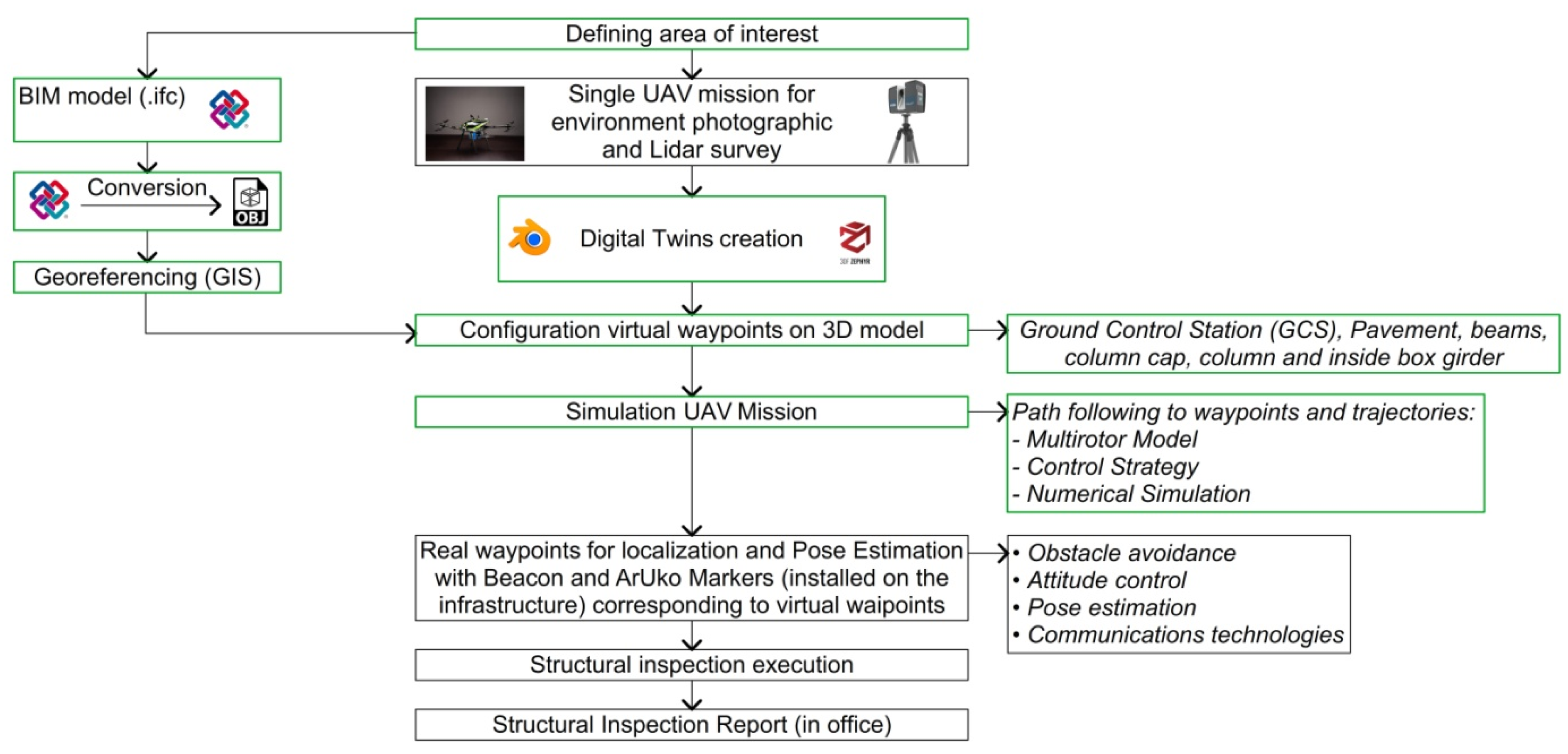
The proposed workflow in Figure 1 gives an overview of each problem to be addressed, in the case that a fleet of autonomous navigation drones is used. On the basis of a digital twin, created simulations of the controller and of the reference trajectories were carried out.
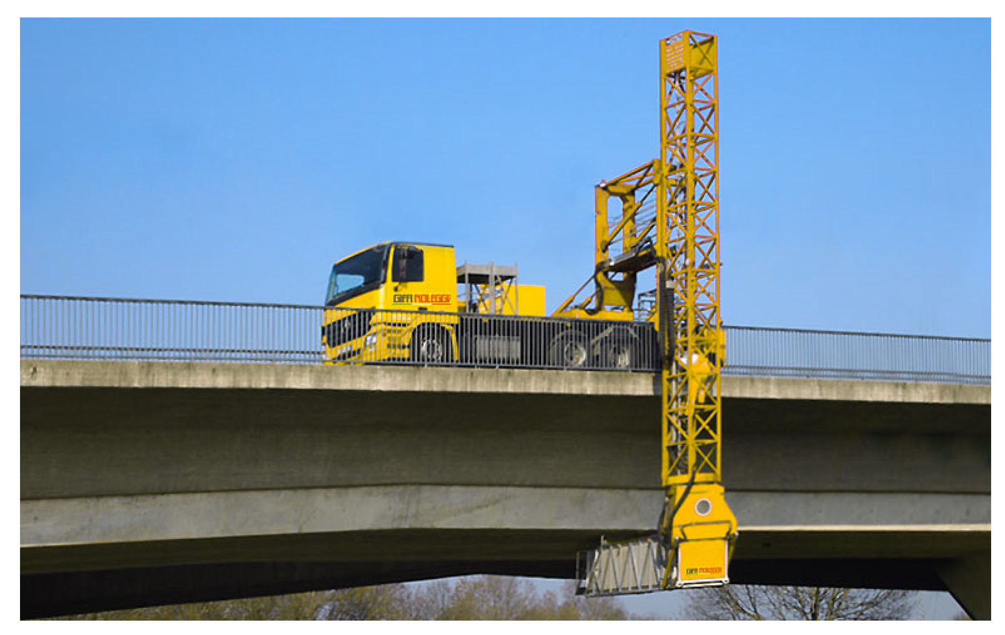
This methodology is proposed for the main inspections, to be carried out with use of a UAV fleet. The UAVs allow to perform periodic inspections of the works remotely and play a primary role in the updating of the digital twin, minimizing risk from manual pilots and for technicians, operators and users. Each piece of acquired information is hypothesized, georeferenced and integrated within the BMSs, to be then easily used by technicians and managers for drawing inspection and monitoring reports. Our work aims to overcome the standard methodologies for pavement, beams, column cap, column, joints and inside box girder inspections of a bridge, which require the use of By-bridge equipment (see Figure 2), Aerial Work Platforms (AWP) or ropes. These methodologies have several limits and risks, especially in difficult to access areas or with obstacles.
3.1. Digital Twin Creation
The paper [23] is based on the idea of feedback control, where a closed-loop training system can be formed by combining real-time information in physical space (digital twin). Furthermore, the work introduces future challenges such as the optimizing the communication interface to realize real-time transmission of data from sensors such as LiDAR and cameras. The paper [16] identified a framework, listing various means of detection but without going into the merits, which divided the digital twin approach into five steps: bridge inspection, BIM model, damage identification, data transmission and facility management. The paper [24] presents initial results of using LiDAR simulation to determine and identify detection gaps, with early prototyping focusing on generating the inhomogeneous point cloud characteristics of the spatial–temporal variability of the LiDAR scanning cycle. The research study [17] introduced a comprehensive methodology for a reliable quality analysis of digital point clouds generated via various techniques, such as imagery acquisition and laser scanning subjected to the implantation of a detailed 3D reconstruction model.
With regards to the methodology proposed in this document, in order to obtain a digital twin representation of the bridge, two alternatives can be distinguished depending on the existence of an infrastructure digital model:
- If a 3D model such as BIM or Bridge Information Modeling (BrIM) exists, then it is possible to work with an interoperable file of Industry Foundation Class type (IFC). This model, however, must be georeferenced. Integrating the BIM model in the 3D territorial context means using coordinates, GIS data, cartographic maps, orthophotos, topographic databases and technical maps. With this base information, we can realistically reconstruct the three-dimensional territory context where our 3D model will be posed. This alternative concerns new structures designed according to a BIM philosophy.
- When the only available information is the project in paper format, which always happens with old facilities, two solutions arise: a digitization of the project in paper format or a new photogrammetry. In the former case, it is necessary to manually build a CAD 3D model from which it is possible to obtain a BrIM. In the latter case, instead, a photogrammetry can be obtained by a single UAV mission equipped with LIDAR, aided by a Laser Scanner total station if necessary. Then, using dedicated software, such as 3DF Zephyr, it is possible to obtain a mesh that is already georeferenced. Finally, using CAD software such as Archicad, a BrIM is obtained from the mesh file. An important advantage of using such a technique is to have at the same time a survey of the geo-morphological and hydraulic area characteristics, aimed to identify the state of decay and main structural and geometric characteristics of the structure, as well the potential condition risks associated with landslides or hydrodynamic actions.
In order to simulate the real UAV in this realistic digital model, it is necessary to create a 3D model of the aircraft itself by using a 3D-modeling software such as Blender.
The steps necessary to create the aforementioned digital twin representations are outlined in Figure 1.
3.2. Virtual Waypoints
In Ref. [24], authors proposed a new and efficient flight path planning method for camera-based aerial inspections of complex 3D structures, more flexible compared to algorithms that only consider path length. The authors introduced the possibility, as a future work, to extend the method to aerial photogrammetry applications and a workflow of the proposed method.
In Ref. [25], the authors present a UAV path planning algorithm developed to navigate indoors and outdoors, useful for Structural Health Monitoring (SHM), which calculates waypoints and vehicle orientation for each location based on Voxelization. The paper [13] presents an algorithm that allows a UAS to provide continuous uninterrupted structural inspection service, suitable for use in multi-UAV waypoint missions.
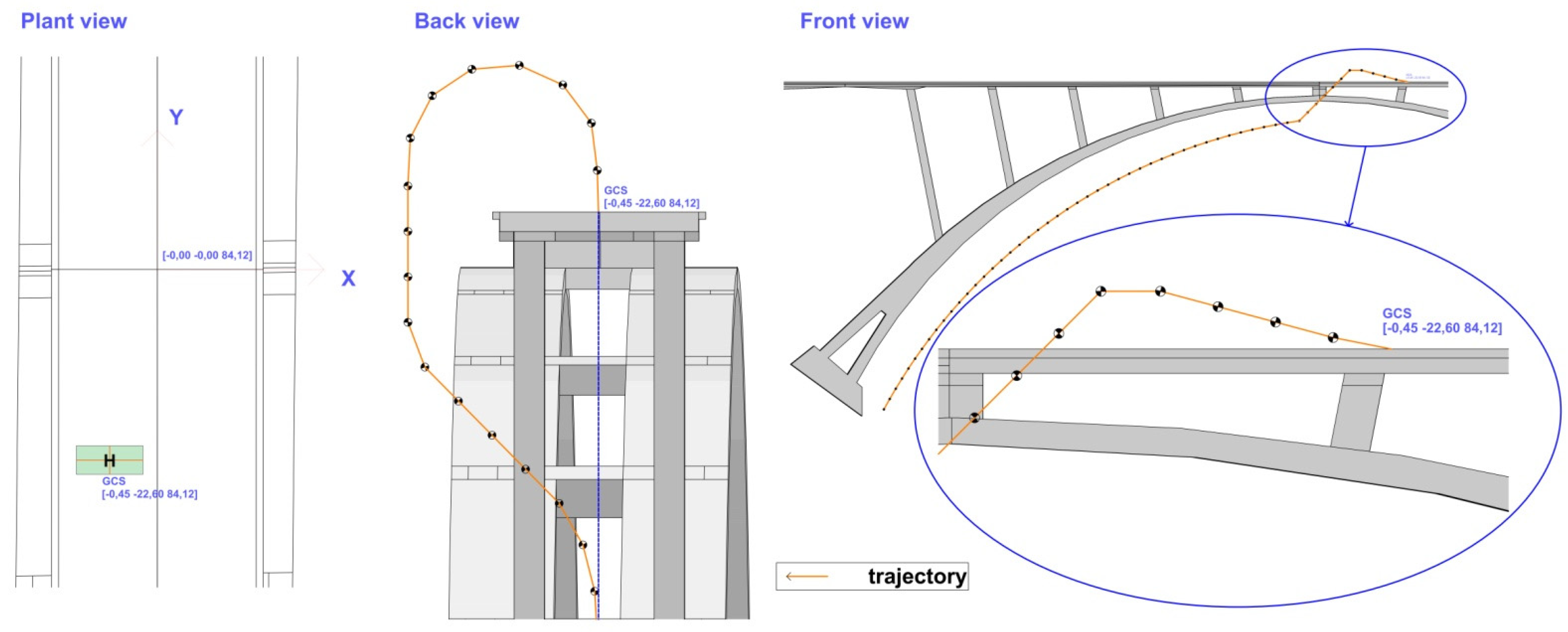
The methodology of this document proposes the choice of waypoints directly on the digital twin representation of the bridge. This operation can be easily carried out by the end-user using dedicated CAD software. Once these points of interest have been established, the proposed methodology allows the automatic generation of UAV trajectories in order to facilitate data acquisition and avoid collisions with other aircraft. Figure 5 shows the selected waypoints for the proposed simulation test.
3.3. Multirotor Model
Regarding the infrastructural inspection, multirotor UAVs are usually preferred for their high maneuverability and hovering ability.
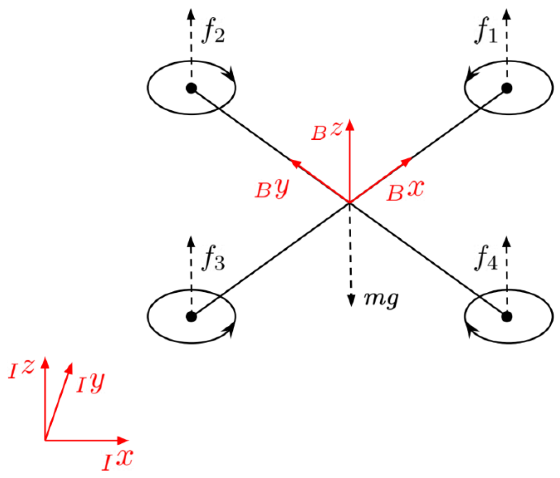
In order to model the dynamics of a generic multirotor UAV (Figure 6), we used two reference systems: the inertial frame and the non-inertial body-fixed frame , both with right-handed coordinates. As left subscripts, these labels indicate the reference system with respect to which a quantity is expressed.
To describe the attitude, the Euler angle convention is adopted. Therefore, the rotation matrix from to is with , and representing the roll, pitch and yaw angle, respectively, and , and indicating rotation about the body-fixed and axes.
The presented model is based on the following assumptions:
- The Center of Gravity (CoG) of the multirotor and the origin of the body-fixed frame coincide;
- The UAV body is rigid and symmetric with respect to the three planes generated by the body-fixed frame;
- No external force, such as wind, is considered.
3.3.1. Translational Dynamics
The translational motion of the vehicle can be expressed using the Newton’s motion equation
where is the position of the CoG expressed in the frame; is the gravity constant; is the mass of the vehicle; is the total thrust generated by the rotors; are the unit vectors along the -axis of the inertial and body-fixed frame, respectively; and is the vector of the aerodynamic forces acting on the UAV. The two aerodynamic phenomena that most influence the motion of any multirotor are blade flapping and induced drag, since they add more damping to the aircraft [26]. According to Ref. [27], it is possible to model the overall effect of these forces through a lumped drug coefficient . This leads to the following expression of the aerodynamic forces:
3.3.2. Rotational Dynamics
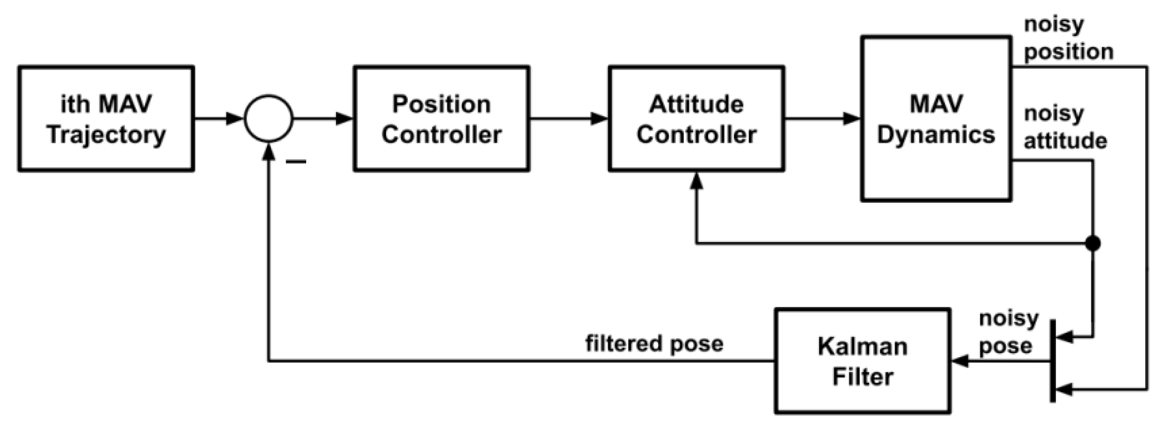
As reported in [28], the most common choice for UAV control is cascade loop: the inner loop is responsible for the attitude control and the outer loop is responsible for position control. The effectiveness of this choice is demonstrated by UAV manufacturers who use it as a standard [29,30,31]. In order to achieve satisfactory performance, the position controller needs to accurately know the inner loop system dynamics. If the attitude controller is known, as in the case of UAV manufacturers, these dynamics can be calculated by simplifying the closed-loop dynamic equations; otherwise, as in this study, simple system identification procedures can be exploited.
We refer, in particular, to the hexacopter and relative identification process used in [32] that lead to the following closed-loop attitude response:
where and are the gains and time constant of roll and pitch angles, respectively; and are the commanded roll and pitch angles; and is the commanded angular velocity of the vehicle heading. The UAV heading angular rate is assumed to track the command instantaneously since the heading has no effect on the UAV position.
3.3.3. State Space Representation
Considering the translational dynamics of Equations (1) and (2) and the attitude closed-loop response of Equations (3)–(5), a possible state space representation is formed by the position and velocity of the CoG expressed in the frame and the attitude parametrized with the Euler angles so that the system state is
and systems inputs are , where is the commanded thrust, which we assume can be achieved instantaneously, as the motor dynamics are much faster than the rigid body dynamics, that is (see (1)). Noting that the same assumption holds also for the yaw command (see (5)), the control input can be written as
Giving importance to the applicability of the proposed strategy in real-world scenarios, we adopt a discrete-time framework, so that the controller can be implemented directly on on-board computers. Therefore, the state update function is
where is the discrete-time variable, is the sampling time and we assume is obtained using the forward Euler discretization method. Regarding the system output, as usual in aircraft control, the measurements are relative to the position and attitude of the UAV. Position data are provided by a positioning system that can be external, such as the GNSS, or on board, such as the visual inertial navigation systems. Attitude data, instead, are usually provided by the on-board inertial measurement units (IMU). Therefore, the output of the system is
where is the measurement noise covariance matrix.
3.4. Control Strategy
As usual in the case of autonomous navigation, in order to allow a fleet of UAVs to inspect a generic infrastructure, we face two distinct problems: (i) the definition of a set of reference trajectories for the individual UAV that allow the aircraft to approach the points of interest avoiding collisions with the other members of the fleet; (ii) the design of a position controller that provides good tracking performance while considering the hardware limitations of the UAVs (maximum thrust, etc.).
The next two sections are devoted to the presentation of the proposed solutions to these fundamental problems.
3.4.1. Trajectory Generation
The generation of UAV reference trajectories is accomplished in two steps:
- Fleet trajectory generation: initially, the user selects a set of waypoints on digital twin (Figure 5) that correspond to the points of interest to be inspected along with the average speed to be maintained during the inspection. With this data, a standard interpolation method or a path planning algorithm can be used to generate a smooth reference trajectory for the centroid (geometric center) of the entire fleet.
- UAV trajectory generation: the fleet kinematic model presented in [33] generates non-colliding trajectories for the individual UAV around the centroid trajectory previously computed.
In order to understand the reasons behind the choice of the model presented in [33], we briefly report here its main features.
Considering n UAVs with one smooth fleet trajectory, that is , the fleet kinematic model consists of a combination of an attractive term to and a hard limiting repulsion function:
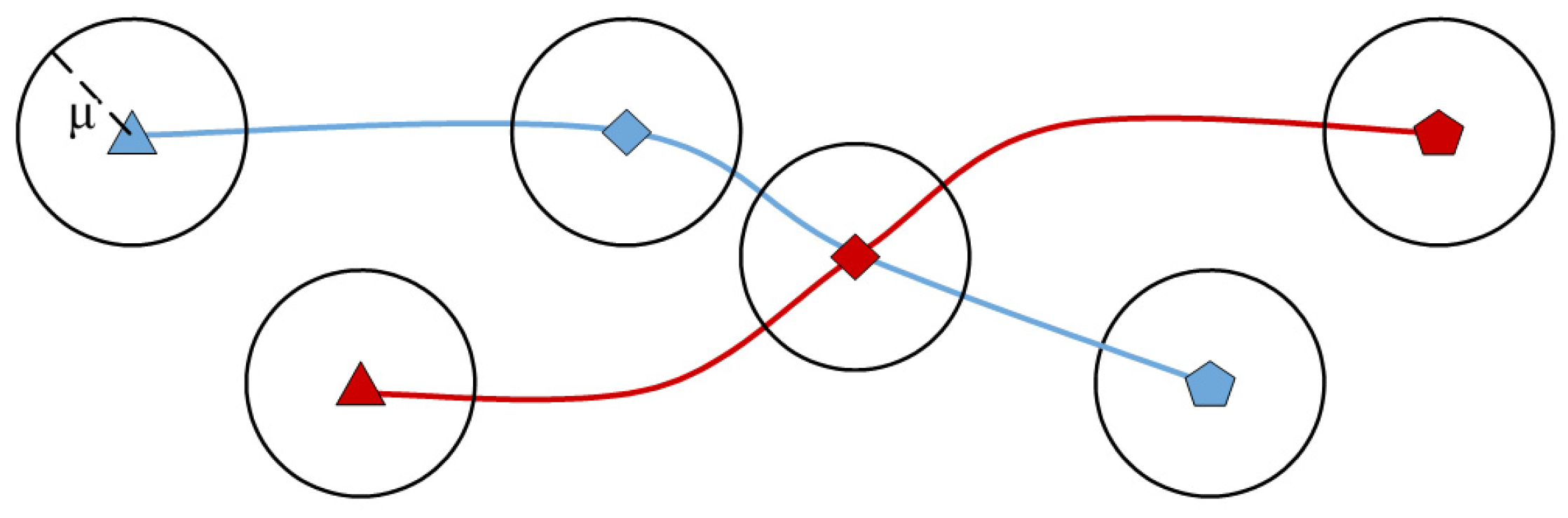
with the position reference for the ith UAV; a full rank matrix; and . The reasons for choosing this model are twofold. The first is its ability to generate trajectories that, at each time instant, are confined into non-intersecting hyper-balls centered at the corresponding current positions and having the same radius (Figure 7). In Ref. [34], this property is formally stated as follows:
Statement: If then holds true and .
The second reason is the ability of the matrix to modify the geometric shape of the fleet, giving the user the possibility to choose between different ellipsoidal formations that can turn into straight line formations (for more details see [34]). In contrast to other formation control algorithms, in this case it is not necessary to specify the distances that agents must maintain between each other to reach the desired formation. This benefits both the scalability of the proposed strategy and the user, who does not need to worry about specifying all the inter-distances.
Along with the position reference, we also provide the UAVs with an attitude reference . Since the purpose of the mission is to acquire data via various sensors, the flat attitude, i.e., zero roll and pitch, is the most advantageous. As far as yaw is concerned, it was chosen to use the angle of the tangent to the trajectory in the x–y plane. Therefore, the attitude reference results in
where is the four quadrant version of the inverse tangent function. Combining the pose and attitude reference in one vector we obtain the reference vector
In order to use such a reference with the discrete-time position controller, we sample it according to the sampling time. For the sake of readability, with an abuse of notation, we denote the sampled trajectory as
3.4.2. Position Controller
In order to accomplish the inspection mission, the position controller must be able to meet two basic requirements:
- Keep the UAV inside the safety hyper-ball considered in trajectory generation. This ensures the avoidance of any collisions between fleet members;
- Handle the hardware limitations of the UAV under consideration (max thrust, etc.).
To this aim, we chose a Non-linear Model Predictive Controller (NMPC). The advantages given by this approach are as follows:
- By using an appropriate cost function in the formulation of the Optimal Control Problem (OCP), the maximum tracking error never exceeds µ, and thus UAVs are always inside the safety hyper-ball.
- The hardware constraints of the platform under consideration are handled formally. This prevents non-linearities introduced by command saturations from degrading performance.
- Using a non-linear model, tracking performance is superior to the linearized version, as demonstrated in [32].
The adopted OCP for the ith UAV is the following
where:
- is the current control interval;
- is the prediction horizon;
- the number of system output variables according to (9);
- is the vector of decision variables;
- is the tuning weight vector for the system outputs, constant for all predictions;
- is the control input admissible set.
Only the first control input is applied to the system, and the process is repeated the next time step in a receding horizon fashion.
3.4.3. State Estimation
Considering that, according to (9), the output of the system does not correspond to the entire state, a state estimator is required to use the proposed NMPC. Since the system under consideration is non-linear, taking as a reference [34], we propose a Square Root Unscented Kalman Filter (SR-UKF) to estimate the UAV state. Compared to the classical version of the UKF presented in [35], this one is computationally more efficient.
The process model of the filter is
with the constant process noise covariance matrix, which is a filter tuning parameter. Exploiting the knowledge about the measurement errors (see Section 3.3.3.), the filter measurement model is the same of the system output reported in (9). The linearity of the measurement model, moreover, further reduces the computational load of the algorithm [36].
Using the SR-UKF, the position controller, at each time step, is provided with an estimate of the entire state, namely . This quantity is actually used instead of the true state in (15).
A scheme of the complete control systems can be viewed in Figure 8.
3.5. Numerical Simulation
In this section we report the performance of the proposed control strategy obtained by using the MATLAB® programming and numeric computing platform. An important aspect in the choice of such environment is the opportunity to generate executable code on the on-board computers of real UAVs from the high-level implementation of the numerical simulation (see in this regard the Model Predictive Control Toolbox™ and the EMBOTECH® FORCESPRO solver [37]). As reported in Section 3.3.2, the chosen UAV is the Asctec® NEO hexacopter, whose physical and dynamic parameters are retrieved from [32] and reported in Table 1. In this simulation, we consider a fleet of three UAVs ().
3.5.1. Reference Trajectories Generation
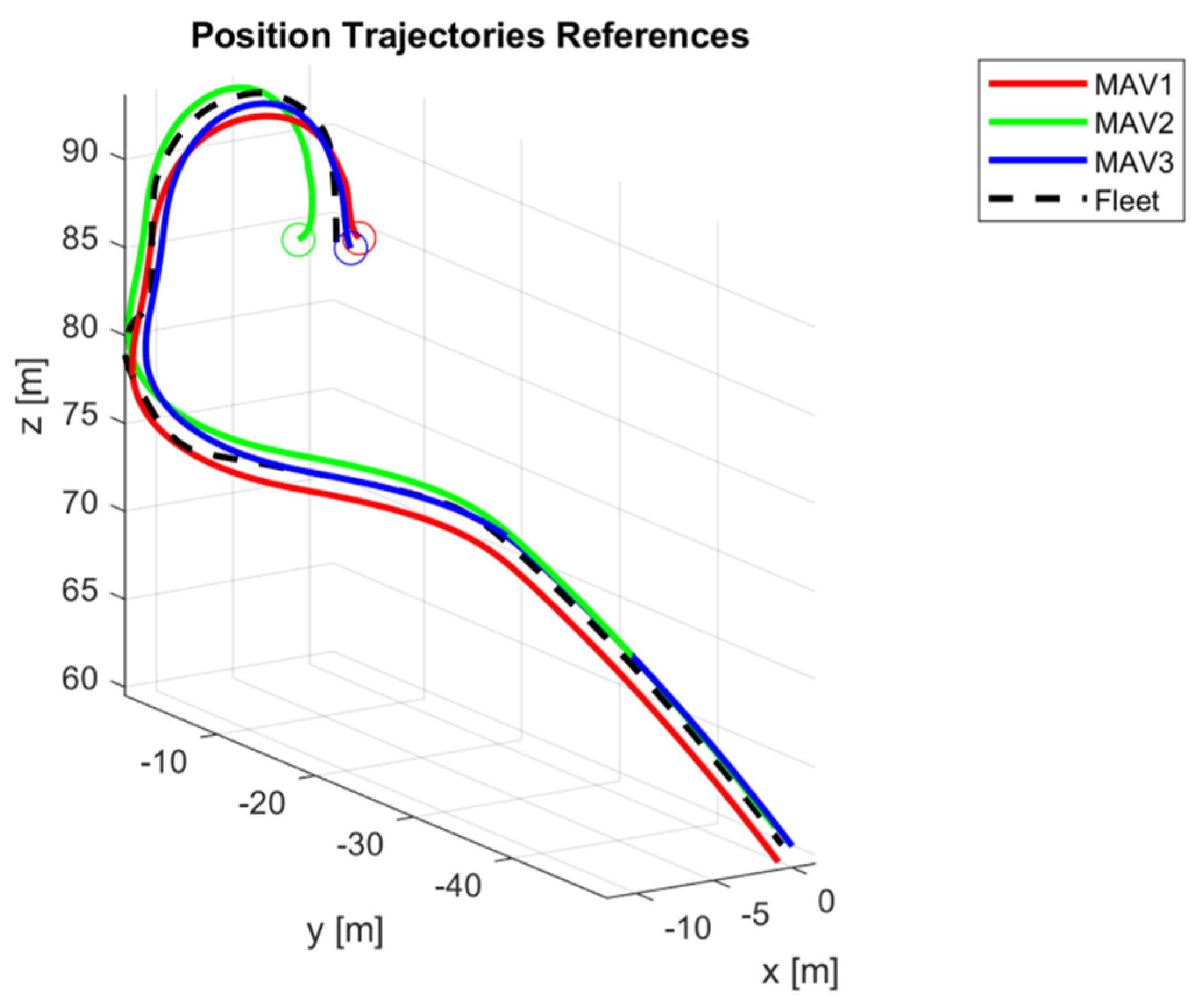
In order to generate the fleet trajectory , Akima splines [38,39] are used to interpolate the chosen waypoints with an average speed of 0.5 m/s.
Next, we considered the generation of the individual UAV position reference trajectory through the fleet kinematic model (10). In order to avoid collision between the aircrafts, the chosen safety radius . Please note that, with such a radius and the UAV initial positions reported in Table 2, the necessary condition of Statement is satisfied. Since the desired approximate shape of the fleet is a vertical line, the interaction matrix is chosen as where the biggest eigenvalue is relative to the z-axis. The speed convergence parameter, finally, is . Once the position trajectories are obtained, using (11), it is possible to compute the complete reference signals . The resulting paths are shown in Figure 9.
3.5.2. Position Controller Setup
The OCP reported in Section 3.4.2. is performed at 20 Hz (), with a prediction horizon and a tuning weight vector that gives priority to the position tracking error. The hard constraints that define the input admissible set are reported in Table 1.
Regarding the setup of the SR-UKF, the constant process noise covariance matrix, which is a filter tuning parameter, is chosen as
and the constant process noise covariance matrix is
where and are the position and attitude measurement standard deviations, respectively.
3.5.3. Results
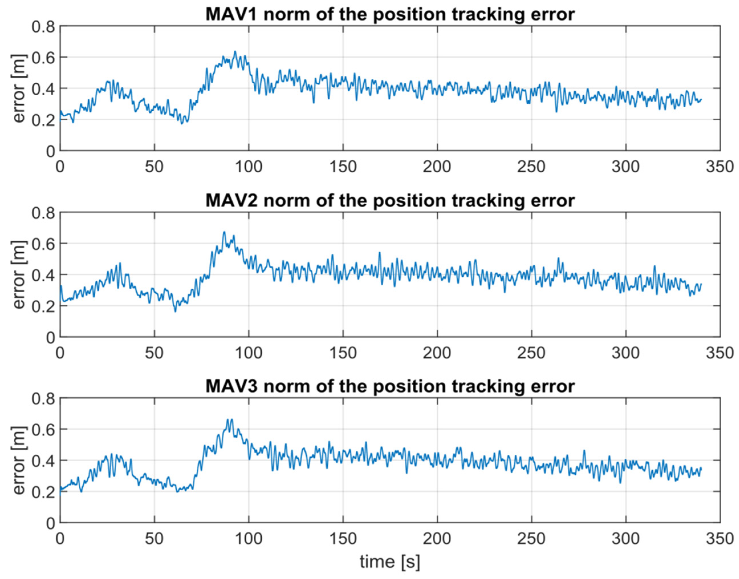
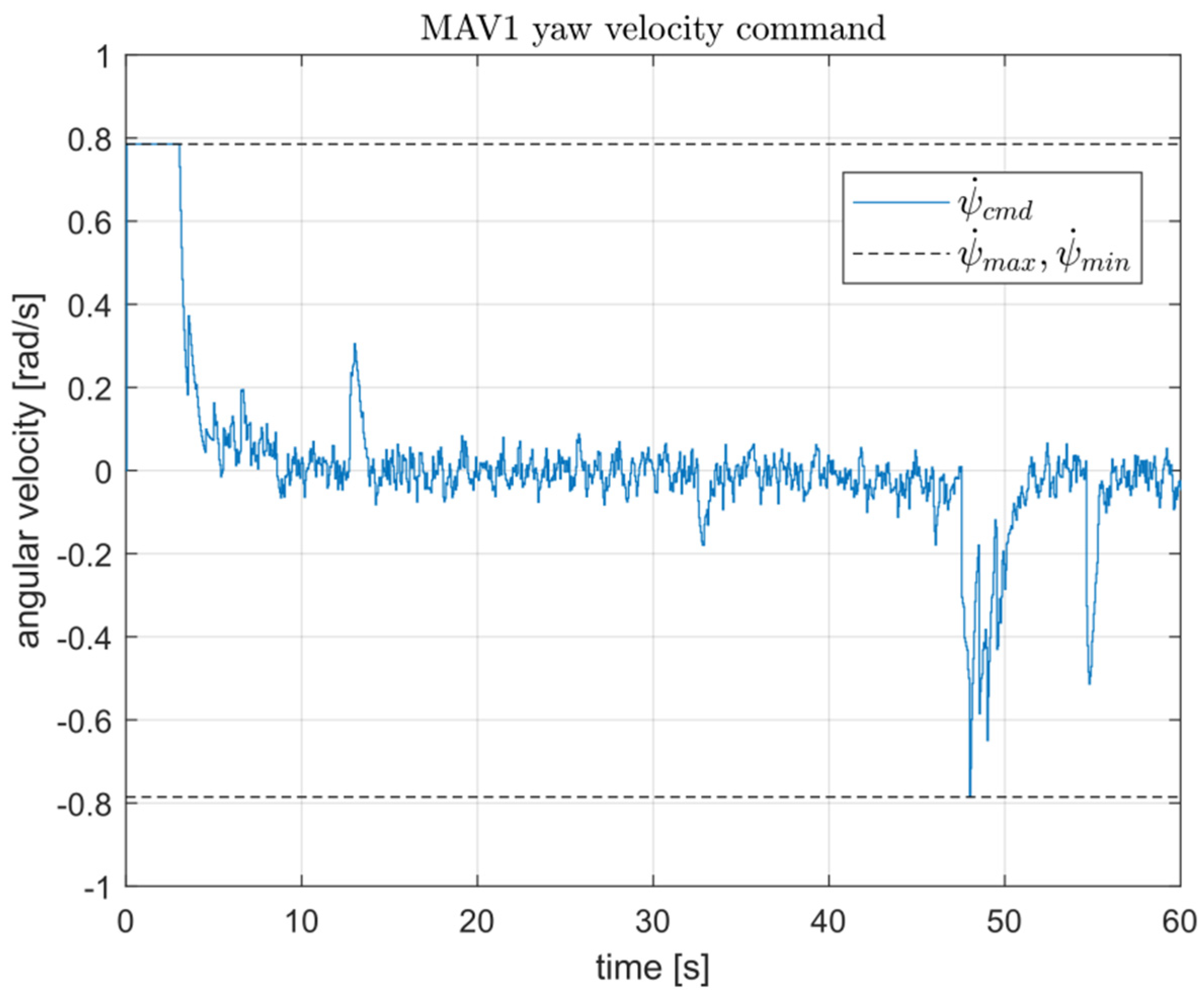
As expected, during the simulation the UAVs track their references despite the measurement noise. Figure 10, in particular, shows how the tracking error norm never exceeds the safety radius µ and, therefore, the UAVs do not collide. Figure 11, moreover, shows an example of input saturation handled by the NMPC. Finally, thanks to the MATLAB® UAV Toolbox Interface for Unreal Engine® Projects, we created a 3D video to better show the behavior of the UAVs during the inspection: [VIDEO].
The operation ends with the automatic writing of the inspection report and the updating of the priority index for predictive maintenance operations as is the case in the current BMS.
4. Conclusions and Future Works
This paper presents a strategy that integrates novel technologies coming from the IT and robotics of a Bridge Management System. Among the different steps that constitute the overall workflow, this work addresses only those related to the preparatory phase of the real inspection. These steps include trajectory planning for a fleet of UAVs based on digital twin representation of the bridge and numerical simulation of the inspection. The simulation results show that the proposed control strategy is effective, since UAVs track their references despite the measurement noise and do not collide.
The steps related to the real inspection will be the subject of future works where field tests will be run. To reach such a goal, several aspects will be considered with great attention: the pose estimation of the UAVs in GNSS denied areas through the solution of the Perspective-n-Point (PnP) problem; the transmission of the collected data to the Ground Control Station through realistic communication channel based on 4G-5G and IEEE 802.11 technologies; and finally, the avoidance of unknown objects near the planned paths, such as vegetation or damaged structural parts.
Author Contributions
Conceptualization, A.B., G.F., A.F. and E.N.; methodology, A.B., L.D., G.F., A.F. and E.N.; software, A.B. and A.F.; validation, G.F. and E.N.; formal analysis, A.B., L.D., G.F., A.F. and E.N.; investigation, A.B. and A.F.; resources, A.B., L.D., G.F., A.F. and E.N.; data curation, A.B., G.F. and A.F.; writing—original draft preparation, A.B., L.D., G.F., A.F. and E.N.; writing—review and editing, A.B., L.D., G.F., A.F. and E.N.; visualization, A.B., L.D., G.F., A.F. and E.N.; supervision, G.F. and E.N.; project administration, G.F. and E.N.; funding acquisition, G.F. and A.F. All authors have read and agreed to the published version of the manuscript.
Funding
This research was funded within the PON R&I (National Operational Program on Research and Innovation) 2014–2020 (CCI 2014IT16M2OP005), European Social Fund, Action I.1 “Ph. D. Studies with Industrial Characterization”.
Institutional Review Board Statement
Not applicable.
Informed Consent Statement
Not applicable.
Data Availability Statement
The article provides all data used in this research.
Acknowledgments
Special thanks for the educational software licenses to: 3Dflow S.r.l. for Zephyr photogrammetry software; GRAPHISOFT Italia for Archicad BIM software tool; and ACCA software S.p.A. for software tools.
Conflicts of Interest
The authors declare no conflict of interest.
Abbreviations
The following abbreviations are used in this manuscript:
| AoI | Areas of Interest |
| AWP | Aerial Work Platform |
| BIM | Building Information Modeling |
| BMS | Bridge Management System |
| BrIM | Bridge information modeling |
| CoG | Center of Gravity |
| GCS | Ground Control Station |
| GIS | Geographic Information System |
| GNSS | Global Navigation Satellite Systems |
| IFC | Industry Foundation |
| IMU | Inertial Measurement Units |
| LIDAR | Laser Imaging Detection and Ranging |
| MAC | Media Access Control layer |
| NDT | Non-Destructive Test |
| NED | North-East-Down |
| NMPC | Non-linear Model Predictive Controller |
| OCP | Optimal Control Problem |
| PnP | Perspective-n-Point |
| SHM | Structural Health Monitoring |
| SR-UKF | Square Root Unscented Kalman Filter |
| UAS | Unmanned Aerial System |
| UAV | Unmanned Aerial Vehicles |
References
- Deng, L.; Wang, W.; Yu, Y. State-of-the-art review on the causes and mechanisms of bridge collapse. J. Perform. Constr. Facil. 2016, 30, 04015005. [Google Scholar] [CrossRef]
- Calvi, G.M.; Moratti, M.; O’Reilly, G.J.; Scattarreggia, N.; Monteiro, R.; Malomo, D.; Calvi, P.M.; Pinho, R. Once upon a time in Italy: The tale of the Morandi Bridge. Struct. Eng. Int. 2018, 29, 198–217. [Google Scholar] [CrossRef]
- Tan, J.-S.; Elbaz, K.; Wang, Z.-F.; Shen, J.S.; Chen, J. Lessons Learnt from Bridge Collapse: A View of Sustainable Management. Sustainability 2020, 12, 1205. [Google Scholar] [CrossRef] [Green Version]
- Santarsiero, G.; Masi, A.; Picciano, V.; Digrisolo, A. The Italian Guidelines on Risk Classification and Management of Bridges: Applications and Remarks on Large Scale Risk Assessments. Infrastructures 2021, 6, 111. [Google Scholar] [CrossRef]
- Akanmu, A. Towards Cyber-Physical Systems Integration in Construction. Ph.D. Thesis, The Pennsylvania State University, State College, PA, USA, 2012. [Google Scholar]
- Ham, Y.; Han, K.K.; Lin, J.J.; Golparvar-Fard, M. Visual monitoring of civil infrastructure systems via camera-equipped unmanned aerial vehicles (UAVs): A review of related works. Vis. Eng. 2016, 4, 1. [Google Scholar] [CrossRef] [Green Version]
- de Freitas Bello, V.S.; Popescu, C.; Blanksvärd, T. Bridge Management Systems: Overview and framework for smart management. In Proceedings of the IABSE Congress Ghent 2021—Structural Engineering for Future Societal Needs, Ghent, Belgium, 22–24 September 2021. [Google Scholar]
- Helmerich, R.; Niederleithinger, E.; Algernon, D.; Streicher, D.; Wiggenhauser, H. Bridge inspection and condition assessment in Europe. Transp. Res. Rec. 2008, 2044, 31–38. [Google Scholar] [CrossRef]
- Achutan, K.; Hay, N.; Aliyari, M.; Ayele, Y.Z. A Digital Information Model Framework for UAS-Enabled Bridge Inspection. Energies 2021, 14, 6017. [Google Scholar] [CrossRef]
- Feroz, S.; Dabous, S.A. UAV-Based Remote Sensing Applications for Bridge Condition Assessment. Remote Sens. 2021, 13, 1809. [Google Scholar] [CrossRef]
- Ciampa, E.; De Vito, L.; Pecce, M.R. Practical issues on the use of drones for construction inspections. J. Phys. Conf. Ser. 2019, 1249, 012016v. [Google Scholar] [CrossRef] [Green Version]
- Zink, J.; Lovelace, B. Unmanned Aerial Vehicle Bridge Inspection Demonstration Project; Minnesota Department of Transportation Research Services & Library: St. Paul, MN, USA, 2015. [Google Scholar]
- Habeenzu, H.; McGetrick, P.; Hester, D. Towards Automated UAV Assisted Bridge Inspections Using Photogrammetry and Image Processing Techniques; CERI: Cork, Ireland, 2020. [Google Scholar]
- Erdelj, M.; Saif, O.; Natalizio, E.; Fantoni, I. UAVs that fly forever: Uninterrupted structural inspection through automatic UAV replacement. Ad. Hoc. Netw. 2019, 94, 101612. [Google Scholar] [CrossRef] [Green Version]
- de Freitas Bello, V.S.; Popescu, C.; Blanksvärd, T.; Täljsten, B. Framework for Bridge Management Systems (BMS) using Digital Twins. In Proceedings of the 1st Conference of the European Association on Quality Control of Bridges and Structures, Padova, Italy, 29 August–1 September 2022; pp. 687–694. [Google Scholar]
- Mohammadi, M.; Rashidi, M.; Mousavi, V.; Karami, A.; Yu, Y.; Samali, B. Quality Evaluation of Digital Twins Generated Based on UAV Photogrammetry and TLS: Bridge Case Study. Remote Sens. 2021, 13, 3499. [Google Scholar] [CrossRef]
- Lei, B.; Ren, Y.; Wang, N.; Huo, L.; Song, G. Design of a new low-cost unmanned aerial vehicle and vision-based concrete crack inspection method. Struct. Health Monit. 2020, 19, 1871–1883. [Google Scholar] [CrossRef]
- Langenkamper, D.; van Kevelaer, R.; Moller, T.; Nattkemper, T.W. Gan-based synthesis of deep learning training data for UAV monitoring. Int. Arch. Photogramm. Remote Sens. Spat. Inf. Sci. 2020, 43, 465–469. [Google Scholar] [CrossRef]
- Saleem, M.R.; Park, J.-W.; Lee, J.-H.; Jung, H.-J.; Sarwar, M.Z. Instant bridge visual inspection using an unmanned aerial vehicle by image capturing and geo-tagging system and deep convolutional neural network. Struct. Health Monit. 2021, 20, 1760–1777. [Google Scholar] [CrossRef]
- Ribeiro, D.; Santos, R.; Shibasaki, A.; Montenegro, P.; Carvalho, H.; Calçada, R. Remote inspection of RC structures using unmanned aerial vehicles and heuristic image processing. Eng. Fail. Anal. 2020, 117, 104813. [Google Scholar] [CrossRef]
- Perry, B.J.; Guo, Y.; Atadero, R.; van de Lindt, J.W. Streamlined bridge inspection system utilizing unmanned aerial vehicles (UAVs) and machine learning. Measurement 2020, 164, 108048. [Google Scholar] [CrossRef]
- Yang, Y.; Meng, Y.; Li, H.; Lu, R.; Fu, M. A Digital Twin Platform for Multi-Rotor UAV. In Proceedings of the 40th Chinese Control Conference, Shanghai, China, 26–28 July 2021. [Google Scholar]
- Riordan, J.; Manduhu, M.; Black, J.; Dow, A.; Dooly, G.; Matalonga, S. LiDAR Simulation for Performance Evaluation of UAS Detect and Avoid. In Proceedings of the 2021 International Conference on Unmanned Aircraft Systems (ICUAS), Athens, Greece, 15–18 June 2021. [Google Scholar]
- Shang, Z.; Bradley, J.; Shen, Z. A co-optimal coverage path planning method for aerial scanning of complex structures. Expert Syst. Appl. 2020, 158, 113535. [Google Scholar] [CrossRef]
- González-deSantos, L.M.; Martínez-Sánchez, J.; González-Jorge, H.; Arias, P. Path planning for indoor contact inspection tasks with UAVs. Int. Arch. Photogramm. Remote Sens. Spat. Inf. Sci. 2020, 43, 345–351. [Google Scholar] [CrossRef]
- Mahony, R.; Kumar, V.; Corke, P. Multirotor aerial vehicles: Modeling, estimation, and control of quadrotor. IEEE Robot. Autom. Mag. 2012, 19, 20–32. [Google Scholar] [CrossRef]
- Omari, S.; Hua, M.D.; Ducard, G.; Hamel, T. Nonlinear Control of Vtol UAVs Incorporating Flapping Dynamics. In Proceedings of the 2013 IEEE/RSJ International Conference on Intelligent Robots and Systems, Tokyo, Japan, 3–7 November 2013; pp. 2419–2425. [Google Scholar]
- Nascimento, T.P.; Saska, M. Position and attitude control of multi- rotor aerial vehicles: A survey. Annu. Rev. Control 2019, 48, 129–146. [Google Scholar] [CrossRef]
- Skydio Software Developlemt Kit on Github. Available online: https://github.com/Skydio (accessed on 14 October 2020).
- Parrot Software Development Kit Webpage. Available online: https://developer.parrot.com/ (accessed on 14 October 2020).
- DJI Development Platform Webpage. Available online: https://developer.dji.com/onboard-sdk/ (accessed on 14 October 2020).
- Kamel, M.; Burri, M.; Siegwart, R. Linear vs nonlinear mpc for trajectory tracking applied to rotary wing micro aerial vehicles. IFAC Pap. 2017, 50, 3463–3469. [Google Scholar] [CrossRef]
- D’Alfonso, L.; Fedele, G.; Franzè, G. Path tracking and coordination control of multi-agent systems: A robust tube-based mpc scheme. IFAC Pap. 2020, 53, 6950–6980. [Google Scholar] [CrossRef]
- Van der Merwe, R.; Wan, E.A. The square-root unscented kalman filter for state and parameter-estimation. In Proceedings of the 2001 IEEE International Conference on Acoustics, Speech, and Signal Processing, Salt Lake City, UT, USA, 7–11 May 2001; Volume 6, pp. 3461–3464. [Google Scholar]
- Julier, S.J.; Uhlmann, J.K. New extension of the kalman filter to nonlinear systems. In Proceedings of the AEROSENSE ’97: Signal Processing, Sensor Fusion, and Target Recognition VI, Orlando, FL, USA, 21–25 April 1997; International Society for Optics and Photonics: Bellingham, WA, USA, 1997; Volume 3068, pp. 182–193. [Google Scholar]
- Tagliabue, A.; Kamel, M.; Verling, S.; Siegwart, R.; Nieto, J. Collaborative transportation using MAVs via passive force control. In Proceedings of the 2017 IEEE International Conference on Robotics and Automation (ICRA), Singapore, 29 May–3 June 2017; pp. 5766–5773. [Google Scholar]
- Domahidi, A.; Jerez, J. Forces Professional. Embotech AG, 2014–2019. Available online: https://www.embotech.com/ (accessed on 7 April 2022).
- Akima, H. A new method of interpolation and smooth curve fitting based on local procedures. J. ACM 1970, 17, 589–602. [Google Scholar] [CrossRef]
- Chan, B.; Guan, H.; Jo, J.; Blumenstein, M. Towards UAV-based bridge inspection systems: A review and an application perspective. Struct. Monit. Maint. 2015, 2, 283–300. [Google Scholar] [CrossRef]
Figure 1.
Workflow of the proposed method. The green border represents the parts implemented in this first phase of work.
Figure 1.
Workflow of the proposed method. The green border represents the parts implemented in this first phase of work.

Figure 2.
By-bridge equipment.

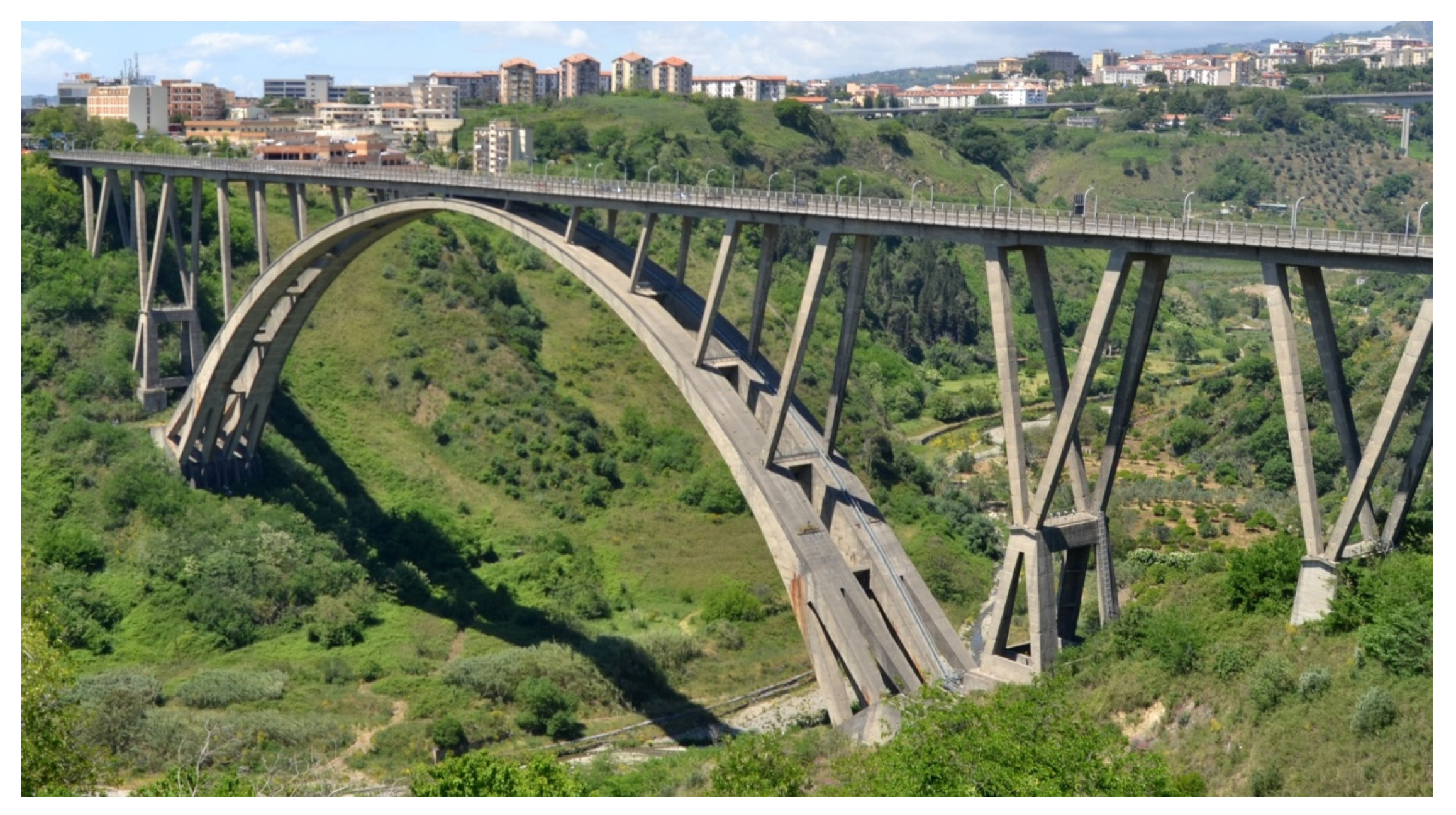
Figure 3.
Morandi Bridge (Catanzaro, Italy).

Figure 4.
Morandi Bridge (Catanzaro, Italy) digital twin creation.

Figure 5.
Morandi Bridge (Catanzaro, Italy) plant, back and right view: trajectory and virtual waypoints in Archicad.
Figure 5.
Morandi Bridge (Catanzaro, Italy) plant, back and right view: trajectory and virtual waypoints in Archicad.

Figure 6.
Inertial and body-fixed reference systems.

Figure 7.
The two lines represent the path taken by two UAVs, while the shapes represent their positions at different times. It is easy to appreciate how, despite intersecting trajectories, collisions are not possible.
Figure 7.
The two lines represent the path taken by two UAVs, while the shapes represent their positions at different times. It is easy to appreciate how, despite intersecting trajectories, collisions are not possible.

Figure 8.
Control cascade loop structure. The attitude controller runs at a higher frequency than the position controller.
Figure 8.
Control cascade loop structure. The attitude controller runs at a higher frequency than the position controller.

Figure 9.
The fleet and UAV position reference trajectories.

Figure 10.
The norm of the tracking error for each UAV.

Figure 11.
The yaw velocity command of the first UAV in the first minute of the simulation. It is possible to appreciate how the NMPC handles the input constraints.
Figure 11.
The yaw velocity command of the first UAV in the first minute of the simulation. It is possible to appreciate how the NMPC handles the input constraints.


Table 1.
NEO hexacopter parameters and control input constraints.
| Parameter | Value |
|---|---|
| mass | 3.42 kg |
| 0.01 s/m | |
| 0.1901 s | |
| 0.1721 s | |
| 0.91 | |
| 0.96 | |
| 45° | |
| −45° | |
| rad/s | |
| rad/s | |
| 40.3 N | |
| 13.5 N |
Table 2.
Initial positions of UAVs.
| MAV | Axis [m] | Axis [m] | Axis [m] | Yaw |
|---|---|---|---|---|
| 1 | 1.5 | −3.39 | 84.13 | 0 |
| 2 | −1.5 | −1.89 | 84.13 | 0 |
| 3 | 0 | −4.89 | 84.13 | 0 |
Publisher’s Note: MDPI stays neutral with regard to jurisdictional claims in published maps and institutional affiliations. |
© 2022 by the authors. Licensee MDPI, Basel, Switzerland. This article is an open access article distributed under the terms and conditions of the Creative Commons Attribution (CC BY) license (https://creativecommons.org/licenses/by/4.0/).
Share and Cite
MDPI and ACS Style
Bono, A.; D’Alfonso, L.; Fedele, G.; Filice, A.; Natalizio, E. Path Planning and Control of a UAV Fleet in Bridge Management Systems. Remote Sens. 2022, 14, 1858. https://doi.org/10.3390/rs14081858
AMA Style
Bono A, D’Alfonso L, Fedele G, Filice A, Natalizio E. Path Planning and Control of a UAV Fleet in Bridge Management Systems. Remote Sensing. 2022; 14(8):1858. https://doi.org/10.3390/rs14081858
Chicago/Turabian StyleBono, Antonio, Luigi D’Alfonso, Giuseppe Fedele, Anselmo Filice, and Enrico Natalizio. 2022. "Path Planning and Control of a UAV Fleet in Bridge Management Systems" Remote Sensing 14, no. 8: 1858. https://doi.org/10.3390/rs14081858
Note that from the first issue of 2016, this journal uses article numbers instead of page numbers. See further details here.