Article

BIM-Based 4D Simulation to Improve Module Manufacturing Productivity for Sustainable Building Projects

1
Department of Architectural Engineering, Graduate School, Hanyang University, 222 Wangsimri-ro, Seongdonggu, Seoul 04763, Korea
2
Department of Architectural Engineering, Hanyang University, 222 Wangsimri-ro, Seongdonggu, Seoul 04763, Korea
*
Author to whom correspondence should be addressed.
Sustainability 2017, 9(3), 426; https://doi.org/10.3390/su9030426
Submission received: 16 November 2016 / Accepted: 7 March 2017 / Published: 13 March 2017

Abstract

:
Modular construction methods, where products are manufactured beforehand in a factory and then transported to the site for installation, are becoming increasingly popular for construction projects in many countries as this method facilitates the use of the advanced technologies that support sustainability in building projects. This approach requires dual factory–site process management to be carefully coordinated and the factory module manufacturing process must therefore be managed in a detailed and quantitative manner. However, currently, the limited algorithms available to support this process are based on mathematical methodologies that do not consider the complex mix of equipment, factories, personnel, and materials involved. This paper presents three new building information modeling-based 4D simulation frameworks to manage the three elements—process, quantity, and quality—that determine the productivity of factory module manufacturing. These frameworks leverage the advantages of 4D simulation and provide more precise information than existing conventional documents. By utilizing a 4D model that facilitates the visualization of a wide range of data variables, manufacturers can plan the module manufacturing process in detail and fully understand the material, equipment, and workflow needed to accomplish the manufacturing tasks. Managers can also access information about material quantities for each process and use this information for earned value management, warehousing/storage, fabrication, and assembly planning. By having a 4D view that connects 2D drawing models, manufacturing errors and rework can be minimized and problems such as construction delays, quality lapses, and cost overruns vastly reduced.

1. Introduction

In construction projects, the many organizations involved in each project introduce a variety of risks due to poor coordination and/or communication in addition to those related to environmental factors, organizations, technology, and resources [1,2]. The concepts of modularization and offsite construction have been developed to handle these construction project risks and optimize the associated processes. These construction methods are based on performing as many of the conventional onsite processes as possible in a factory beforehand to reduce onsite construction costs, save time, and promote construction safety and quality [3,4,5]. Modular construction can help the construction industry fully achieve the goals of sustainability alongside the many benefits mentioned above [6]. To improve the productivity and sustainability of modular construction, detailed quantitative management of the factory module manufacturing process that critically affects the overall project performance is essential. However, the module manufacturing process is complex as a wide variety of resources are involved in manufacturing products for multiple projects, so careful planning is vital.
Because almost all project information consists of a combination of static and passive information created using 2D computer-aided design (CAD) or handwork [7,8,9], the workers assigned to these manufacturing processes in a factory environment need to learn a massive amount of diverse project information, much of which may be irrelevant for their particular manufacturing role [10]. To improve the productivity of the module manufacturing process, workers must be provided with detailed and accurate information at the right time [10].
A variety of methodologies have been proposed to optimize the factory module manufacturing process, including mathematical analyses for process planning in multiple projects under multiple resource environments [11,12], heuristic techniques for calculating the parameters of processes that require minimum costs [13], a generic algorithm for finding a process that minimizes work time [14], and a simulation-based mathematical approach [15]. However, most of these depend on mathematical analyses and have only a limited ability to carry out multiple analyses of various variables in an actual module manufacturing environment [16]. These methodologies are generally also very complex and thus difficult for non-specialists such as managers and those working on the factory production line to use.
Building information modeling (BIM) is the latest methodology that has been developed for managing processes, material quantity/costs, and quality [17]. A 4D simulation that connects process information to a 3D model based on parametric information can be used to visualize construction information such as processes and resources. This promises to be a particularly useful methodology for modular construction processes because 4D visualization technology exploits the complex relationships between entities to streamline processes and reduce and/or eliminate non-value adding activities.
In the research reported here, a 4D framework was developed that is capable of managing processes, resources, and quality based on factors related to the module manufacturing environment such as the factory layout, equipment and processes available, material quantities required, and 2D drawings.

2. Literature Review

2.1. Modular Construction

In modular construction, standard materials are used to manufacture modules in a factory environment where external factors can be controlled. These modules are then transported to the site, hoisted into position by a crane, and installed in their designated locations [3,4,5,18,19]. This method provides a variety of productivity-related benefits related to processes, costs, and quality. Site preparation and construction can be performed simultaneously [20], and module manufacturing is not hindered by the weather [21]. The risk of construction delays due to property damage or theft is reduced [22,23], and construction time can be reduced by up to 40% compared to traditional construction methods [24,25]. It has been shown that the overall construction costs can be reduced by 10% and onsite labor costs by 25% in modular construction compared to those incurred on a traditional construction site [26]; manufacturing costs can be reduced by minimizing personnel and material investments and making large-scale resource purchases [27,28]. Modular construction maximizes task efficiency and minimizes task complexity by reducing onsite labor [29]. In addition to the abovementioned benefits, modular construction also provides a variety of quality-related benefits. For example, rework and the use of automated equipment increase product quality, and the task specialization that becomes possible on product lines improves workers’ skills and reduces defect rates [30,31,32]. Many researchers have identified additional benefits such as an enhanced ability to withstand impacts and handle stacked loads during transportation and installation, the greater use of lightweight materials, higher weather resistance, and minimal site exposure [21,23,28,33,34,35].

2.2. Module Manufacturing Process Management

The main risk associated with modular construction is that the uncertainty encountered at the modular construction site and the factory can mutually influence the process and reduce productivity. It is particularly important to manage the productivity of the various module manufacturing processes, as delays at this stage can have a serious knock-on effect that adversely impacts later processes such as module transport, site delivery, hoisting, and installation [19,36]. Risks such as insufficient manufacturing planning, limited work time, limited resources, spatial interference, reduced worker performance, and information limitations can lead to module manufacturing work delays, increased costs, and inferior quality [16,37,38,39,40]. In particular, module manufacturing process management may fail due to a lack of adequate planning to ensure the necessary materials, resources, and workers are in place, all of which are critical elements that govern productivity at the factory module manufacturing stage [16,39,40].

2.3. Limitations of Existing Research on Module Manufacturing Process Management

The module manufacturing process is resource-constrained in a confined space, with multi-project management characteristics. To resolve the resource-constrained multi-project scheduling problem, researchers have applied several different methodologies (Table 1), which can be loosely classified as either heuristic approaches or mathematical analyses. These include zero–one programming techniques, branch-and-bound dynamic programming, and genetic algorithms [11,12,13,41,42,43,44]. A new methodology has been proposed that combines genetic algorithms and heuristic techniques [14,41], but this type of approach suffers from a limited ability to optimize factory processes that involve clustered variables such as resources, equipment, people, and processes.
In Borrego’s model, a module manufacturing yard schedule is created that determines and simulates the order of priority based on priority dispatching rules and 3D visualization [45]. Here, the simulation model for each event is connected to a module manufacturing yard where a variety of processes occur simultaneously, and the interactions between these processes are analyzed. Liu extended this by assigning a physical space to each event in a multi-agent model that is then applied to an agent-based simulation platform [46]. However, the simulation rules applied in each of these models are once again based on a mathematical analysis approach, which is inherently unable to derive connections between processes and spaces/resources.

2.4. BIM-Based 4D Simulation

BIM-based 4D simulations seamlessly connect 3D graphics and resource components to the process schedule to provide Critical Path Method (CPM) plans or schedule information on a 4D screen [51]. Since this technique was first introduced 20 years ago, extensive research has been devoted to exploring its capabilities. The first BIM-based 4D simulation was the Activity Level 4D Model (AL4M), which simply matches construction process information with 3D model objects of construction materials [17,52]. The biggest drawback of this model is that it is unable to perform 4D model analyses that include temporary components such as the types of resources and equipment typically needed for construction, or with resource components such as workers, materials, and costs, rendering it unsuitable for safety, quality, and productivity analyses [53].
To address these limitations, Huang et al. proposed the Operation Level 4D Model (OL4M), which connects construction virtual prototyping technology to 4D modeling to perform actual graphical simulations [54]; Dawood et al. developed a framework that is capable of performing virtual construction site modeling for 4D process analysis [55]; and Adjei-Kumi et al. proposed a 4D model called PROVISYS, which uses process information to derive site use processes for resources such as equipment and personnel [56]. Of these, the OL4M process management system [54] is of particular interest as it is takes into account factors such as resources, workforce, equipment, physical space, schedule and materials that are involved in the module manufacturing process. This model performs multiple functions, including the visualization of complex interactions between the various resources and both managers and workers [52], thus increasing the accuracy of project schedules and improving the coordination between different activities [54]. Operation level 4D enables planners to monitor the schedule and identify potential problems before actual construction begins. In addition, it supports a more intuitive grasp of the on-site process than either traditional 2D drawings or scheduling applications such as Gantt or program evaluation review technique (PERT) charts [57]. OL4M also enables users to differentiate between the various uncertainties that are likely to occur during individual processes and provide appropriate information so users can plan how to deal with these in advance [58].

2.5. BIM-Based 4D for Managing Module Manufacturing

The module manufacturing activities that take place in the factory are stochastic and dynamic in nature and changes within activities occur as a variable of time [59], hence the decision to utilize a BIM based 4D simulation model for this research. Computer based modeling is widely used for the simulation and analysis of economic problems and is known to be an efficient tool for the optimization of project productivity, represented here in terms of the schedule, and the quantity and quality of the output [60,61]. In the context of project management, a project management tool based on 4D simulation is an effective and popular method which facilitates the exploration, description and interpretation of the processes and behaviors involved in construction projects. [59] There is clearly a need for both short-term management (of the order of an hour or a shift) that can resolve problems quickly and accurately by measuring task procedures and resource quantities and then producing modules suitable for short processes, as well as long-term management (that might depend, for example, on the day of the week [19]) that provides the parametric information required to achieve goals related to the module manufacturing schedule, material quantity, and quality [62].
The BIM-based 4D model developed for this study was therefore based on BIM models with a high level of detail (LOD) equivalent to that found in design document standards, allowing detailed schedule information to be mapped into the 4D model. Various module manufacturing activities can be visually represented within a short working period to create a site environment that includes factory BIM models and equipment sets, making both short- and long-term simulations possible. The use of a 4D model also makes it possible to produce material quantities for specific time periods, provide relevant material quantity information to production workers according to the part being manufactured, and display continuously updated material quantity information to managers to facilitate the management of manufacturing warehousing, storage, and workflow. Finally, by linking 4D models and 2D drawings using floor, section and elevation plans, the numeric and shape information contained in the 2D drawings can be directly compared with the 3D BIM models to identify design errors and model interference, enabling workers to perform a quality check on the manufactured module.

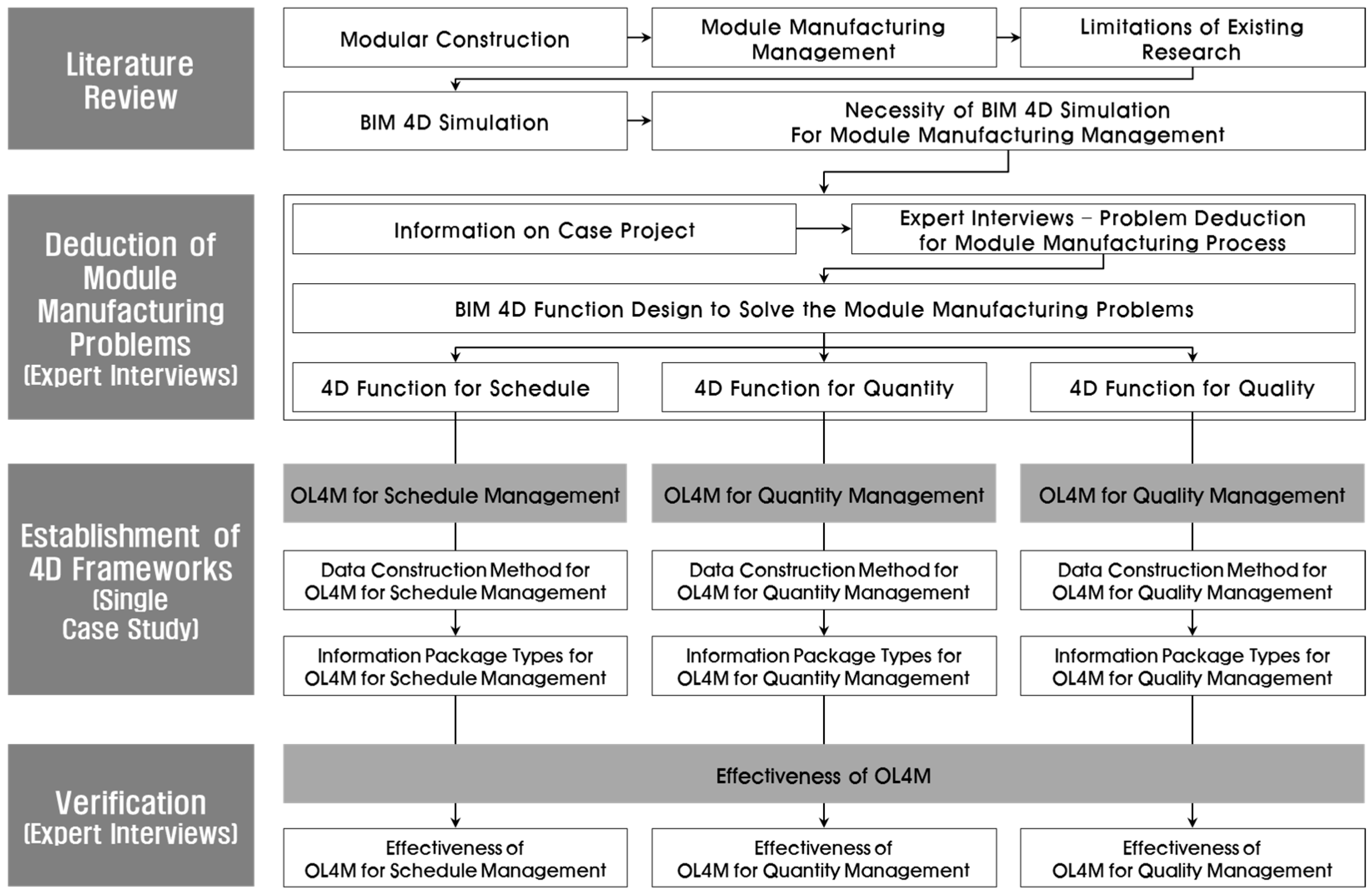
3. Research Approach

The first objective of this research was to identify the schedule, quantity and quality problems that occur during real world module manufacturing processes using expert interviews. Based on the problems identified, comprehensive, informative and practical 4D BIM-based frameworks were then developed for scheduling and quantity and quality management of the module manufacturing process in the factory. In order to investigate how these frameworks could be integrated into current working environments, follow-up interviews were conducted with the experts to elicit their opinions of the practicality of the proposed frameworks.
A single case study methodology was selected for this research, which was based on the types of problems related to scheduling, material quantity and quality experienced in the module fabrication phase of the “G Project” in South Korea. Three 4D simulation frameworks were developed to deal with the issues identified. The single case study is useful research tool for the preliminary exploratory stage of a research project of this type because it brings a fresh perspective to the problem being considered [63,64]. In a specialized goal-oriented environment such as a module manufacturing factory, it is possible to track changes in strategy and resources in detail, as well as the organizational and individual approaches used to handle such changes [65].
The framework used for implementing 4D simulation technologies for the module manufacturing process is illustrated in Figure 1. The initial activity level for the 4D model is established by linking the module’s BIM model with sequence information (*.csv file format) to simulate the overall manufacturing plan. Three types of OL4M controlling the managerial problems related to the schedule, material quantity and quality were deduced based on the expert interviews. The common input information for all three types of OL4M consists of the 2D drawings of the case module; the factory floor plans, the time schedule for the work, daily manufacturing work reports and equipment specifications are then collected, along with information on the module being constructed, and the factory space and equipment available. Finally, the OL4M framework was broken down into the OL4M for the schedule (OL4MfS), the OL4M for material quantity (OL4MfM, which includes the bill of material (BOM) information), and the OL4M for quality (OL4MfQ, which includes the 2D drawings and is directly attached to the 4D model). The data utilized in this research were extracted from 2D CAD drawings, including shop drawings of the module, and the schedule and daily work reports for the factory provided by the designer and the factory manager.
The research process shown in Figure 2 was followed to develop the BIM 4D framework for module manufacturing management used in this study. The process began by performing a comprehensive review of the research literature on this topic to identify the aspects necessary for applying the BIM 4D simulation to module manufacturing management. This review served as the basis for a series of interviews with experts in the field to understand the problems they were experiencing with existing module manufacturing factory management tools and develop an in-depth understanding of the BIM 4D framework functions needed to handle these problems. The information gathered was then applied to develop a new BIM 4D framework, OL4M, capable of resolving the problems with processes, material quantity, and quality that were afflicting the case study project.

4. 4D Framework Design

4.1. Case Project Information and Interview Results

Seoul’s “G Module Housing Complex” was selected as the case project guiding the development of the Operation Level 4D Model for Schedule Management (OL4MfS, OL4MfM, and OL4MfQ) to facilitate the collection of real world data on modular building methods and gather feedback on the new model’s performance. The project also provided optimal conditions for conducting interviews with both experts and practitioners in the field. Interviews (Table 2) were conducted with 10 project experts on problems pertaining to processes, resource quantity, and quality to identify the problems commonly experienced with module manufacturing. The issues raised by the experts were then addressed when designing the functions of the new 4D simulation framework, the ultimate goal of this research.

4.2. Design of 4D Framework Function

4.2.1. 4D Functions for Project Schedule

Conventional shop drawings and specifications typically include errors due to discrepancies between the plan, elevation, and section views as well as between the drawings and specifications. The process tables normally used cannot show detailed process activities because the design company is generally not familiar with the precise details of the manufacturing process. In addition, traditional media do not provide comprehensive information regarding the various planning models related to the factory, equipment, materials and so on, leaving the factory to manufacture modules based on limited information such as shop drawings, milestones, expertise, and experience. This inevitably causes a variety of process-related errors such as work delays, failure to use space optimally, equipment operations failures, and process/workflow interference. To resolve these process problems, a detailed integrated visual information medium is needed. 4D simulation can provide a view that is more visually detailed than simple case project process information, and this also makes it possible to show detailed manufacturing processes for each part being manufactured. It then becomes possible to create planning models that are connected to specific factories and pieces of equipment and include new information on measurements, space, and quantities. Table 3 lists the problems with module manufacturing scheduling identified in the interviews and the 4D functions used to resolve these problems.

4.2.2. 4D Functions for Material Quantity

The material quantity information provided in the case project consisted of a material quantity take-off document produced by 2D estimation; specific material quantity information for the individual part being manufactured and manufacturing process being used is not normally provided. This means that manufacturers are not able to make detailed prior preparations for materials, resulting in manufacturing process delays and management failures. Precise material quantity information from the 3D model and detailed simulated material quantity information according to the manufacturing process are needed. This can be obtained based on accurate 4D material quantity information for each process, which can be derived by combining the process information and material quantity information obtained from the BIM model. Table 4 lists the additional information needed to handle material management problems and the associated BIM 4D functions.

4.2.3. 4D Functions for Project Quality

If the module quality is poor, this can lead to construction errors during the module assembly stage at the construction site, adversely affecting the final quality of the completed building. It is thus important to ensure that the drawings that affect the module manufacturing quality are accurate. However, in the case project factory, the drawing consistency was either not verified or could not be verified before manufacture, and the workers failed to understand the problem, with a consequent negative impact on quality. This created the additional risk of work delays due to the need for extra training programs, error correction, and reworking. To resolve these quality problems, it is essential for the consistency of the drawings to be enforced; even if it is considered a logically error-free drawing, it is necessary to ensure consistency by comparing it with the model. By linking the drawing with a 4D simulation, it is possible to perform precise verifications by checking the drawing information for each process in real time through its connection with the 3D shape information, verifying the quality, and directly comparing the drawing and model (Table 5).

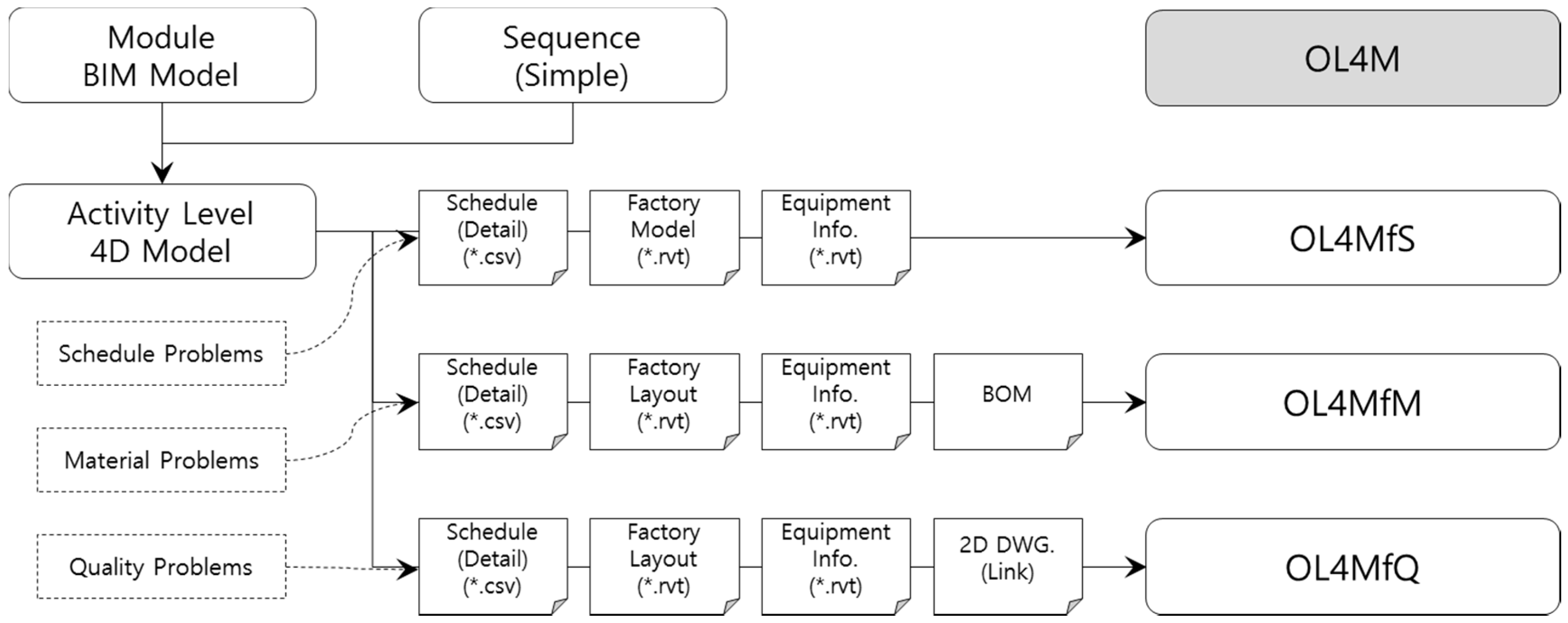
5. Preliminary BIM-Based 4D Frameworks

5.1. OL4M for Schedule Management

5.1.1. Data Construction Method for OL4MfS

To develop OL4MfS, BIM of a module was conducted based on the case project’s module manufacturing documents. The milestones used in the case project provided only simple high-level process information. The detailed start date, finish date, and period for each activity (Table 6), all of which are needed to manufacture the model, were obtained from the daily work reports and mapped onto the module’s model object to create that module’s 4D model. In addition, as shown in Figure 3, a factory BIM model and an equipment/material BIM model were created to show a 4D process plan simulation of the factory operation plans related to the process, equipment use, and so on.
The factory, equipment, and BIM models of the module were then imported into Navisworks Manage 2016 to create an integrated model for OL4MfS, as shown in Figure 4. The integrated model includes BIM models of the modules, factories, overhead travelling cranes, exterior crawler cranes, forklifts, some materials, and other relevant factors, as well as the detailed process information obtained from the daily work reports.
To create the detailed process simulations for each line, module models for parts 1–10 (of a single model) were precisely arranged on a coordinate grid according to their part number and the process information mapped, again according to the part numbers, to create a simulation where each process corresponded to only its own part.
This process took a total of 81 h, including 48 h to create the module model for OL4MfS; 24 h to model the factory, equipment, and materials; and 9 h to produce the detailed process simulation and various 4D plan models such as the equipment operation plans. OL4MfS doubled the number of processes shown in the case project’s flowchart (rising from 28 to 56) and mapped each so that detailed processes could be shown according to the part to be manufactured.
The 4D model’s object-to-schedule ratio was
O:S = N:1 (N ≥ 1)
where O is the number of module objects in the BIM model and S is the number of mapped schedule activities.
This means that specific BIM model objects can be mapped to their process information at an object-to-schedule ratio greater than 1:1. A 4D simulation can thus be created to include more activities than the case project’s processes, providing the manufacturers with more detailed visual information.

5.1.2. Information Package Types for OL4MfS

Through the abovementioned tasks, an OL4MfS framework was completed that could perform detailed process simulations for each individual part as well as produce two types of planning models, including equipment planning. First, the detailed process according to the part is developed using a variety of equipment and materials and factory environments. The unit bathroom (UBR) manufacturing and installation processes, which involve complex interconnected processes such as crane and forklift equipment usage and material fabrication, storage, and installation, are developed through sample simulations. The detailed simulations of the UBR manufacturing and installation processes show the interior factory environment where manufacturing processes and tasks are carried out based on the workflow and process information for the specific equipment (cranes, forklifts) used in the task. This makes it possible for users to conduct prior training and virtual practice on future manufacturing processes based on the manufacturer’s detailed understanding of processes, selection of manufacturing methods, equipment use, and material storage and fabrication. This type of training and practice helps eliminate problems such as work delays and plan failures.
Second, an exterior storage plan model was created for removing the packaged modules from the factory and loading them onto the trucks transporting them to the site. The 4D module storage plan model is composed of a module movement plan and factory layout plan. The module movement plan includes workflow, crawler crane lifting, and open storage areas, while the factory layout plan incorporates crawler crane locations, crane rotation radius and lift height, interference checks for cranes and nearby buildings, dump truck movement workflow, and maximum storage space for open storage areas.
Figure 5 shows the 4D plan model created using OL4MfS. The main benefit of OL4MfS is that although it has a relatively small number of resource requirements, it combines two kinds of planning models to provide various resource usage details, physical interference details, and factory layout plans, none of which can be obtained using existing module manufacturing methods.

5.2. OL4M for Material Quantity Management

5.2.1. Data Construction Method for OL4MfM

The OL4MfM framework, which connects OL4MfS with material quantity take-off reports, is produced based on the property information volume for the module source model (.rvt). To obtain the material quantity information for a specific process, the object material quantities are categorized according to the process information mapped to OL4MfS so that the material quantity for the part being manufactured can be found. Figure 6 shows how the material type and number of each type, the unit material quantity, and the total quantity can be presented. To achieve this, the material quantity information (.csv) in the Navisworks model is mapped in the same way as was done for OL4MfS and the material quantity information is assigned for each activity listed in the Timeliner, thus yielding the material quantity information for each activity. The quantity take-off units differ according to the material type (e.g., pipes are measured in m, gypsum board in m2, and doors as ea). This allows the groups to be defined beforehand according to the quantity production unit shown in the project parameters to selectively create quantity production by material type.
OL4MfM can create an output simply by mapping the material quantity information produced in Autodesk BDS 2016, which is used in the module model, to the Navisworks model (.nwd), once again following the same procedure as OL4MfS. To connect the BDS-based BOM output to the Timeliner, 1 h is required. The data structure and properties are almost identical to those of OL4MfS, except for the mapping of the material quantity information to the Timeliner. The object and process linkage relationship; number of mapped processes, expressed work types; and number of BIM model objects are all the same.

5.2.2. Information Package Types for OL4MfM

OL4MfM was designed to provide material quantity information for each individual part for use in conjunction with the simulation of OL4MfS manufacturing for that part. In existing material quantity take-off (QTO) documents and manufacturing bills of material (BOM), material quantity information is not provided for each part and blanket purchases are thus made based on the combined BOM and QTO documents, with manufacturers that need specific parts selecting the appropriate quantities of each material required.
To resolve this problem, a 4D model (.nwd) with material quantity information mapped to the Timeliner can be provided to factory managers, along with a material list (.csv) collected directly from the model authoring tool the manufacturers also receive and a detailed process simulation according to the part. Factory managers can then construct a variety of cost and material plans using OL4MfM and the Timeliner, with material quantity information mapped according to individual process activities. In addition, the experienced workers responsible for each part gain an understanding of the approximate material quantities they will need, which are otherwise simulated for their processes through OL4MfS and the material quantity take-off documents provided. Resource preparation, storage, and manufacturing tasks can thus be performed without delay, reducing congestion at the work site. Figure 7 shows the CSV-format BOM, in which the module model’s material quantity information originally mapped to the process information modeled by Autodesk BDS 2016 was instead produced and arranged through the BOM function. The start date, finish date, and material quantity information were matched according to the process activity (Display_I.D).

5.3. OL4M for Quality Management

5.3.1. Data Construction Method for OL4MfQ

To create the UBR manufacturing and installation portion of the new model, OL4MfQ, the origin point of the second part of the 4D model and the origin point of the floor plan and section view (.dwg) in the UBR shop drawings were superimposed and the drawings imported directly into Navisworks. The resulting OL4MfQ is shown in Figure 8. The origin point coordinates of the 2D shop drawing (.dwg) are directly linked and unnecessary marks such as the template, symbols, and hatching deleted, with each part of the integrated 4D model (.nwd) of OL4MfS matching the model. In total, an additional 5 h was required for OL4MfQ, including the time for editing and linking the drawings and creating the 4D drawing-linked model. The 4D simulation corresponding to the detailed simulation model’s main floor plan and cross-sectional parts in relation to the part being manufactured is the same as for the OL4MfS 4D simulation information package, except for the inclusion of the drawing. The expressed objects, LOD, object-process linkage relationships, and process count are all the same.

5.3.2. Information Package Types for OL4MfQ

OL4MfQ was developed to encourage factory manufacturers and managers to review module design quality, thus improving the quality of the manufactured modules and reducing costs, and to reduce the time required for drawing reviews and training staff. As Figure 8 shows, drawings such as plans and sections for parts that are expected to have complex designs or are difficult to manufacture are linked to OL4MfS’s basic 4D simulation, allowing the module and model to be modeled simultaneously. By mapping the process information to a drawing linked to the 4D model, it can be made to repeatedly appear and disappear with the model’s process, allowing factory workers to successively check the drawings needed for each process in 4D without needing to review the individual drawings for each step.
In addition to the advantages of 3D training, better process understanding, and material quantity reviews for manufactured models, factory workers can also be provided with shape and numerical information, which makes it possible to learn through documents alone. Segmented information media such as conventional 2D drawings, process tables, and specifications are all included within the same OL4MfQ model, and by visualizing the various pieces of information, the information can be intuitively and visually understood. By using OL4MfQ, manufacturers and managers can reduce the amount of time required for drawing reviews and training to a minimum. In addition, by linking drawings directly to the 4D model, it is possible to maintain the necessary consistency between the drawings and model.
Here, reviewing the consistency between a drawing and model is a fundamentally different concept from simple BIM-based clash detection when viewed from a quality management perspective. BIM-based clash detection is performed to manage conflicts between participant models [66]. A review of the interference between models that have already been constructed can never provide a comprehensive design quality review. For example, if clash detection is performed on a construction model and structural model containing design errors, interference will not necessarily be detected and design errors may not be discovered through an interference review. In contrast, by using OL4MfQ, manufacturers and managers visually review the drawings and models according to the process order, allowing them to make direct visual comparisons and thus avoid potential sources of waste in module manufacturing, such as errors and rework, and improve the quality of the modules produced.

5.4. Comparison of Information Package Types for the Three OL4M Frameworks

Table 7 provides a comparison of the resource requirements, models, and data structures for OL4MfS, OL4MfM, and OL4MfQ. All three model structures are very similar; the three OL4M frameworks all produce excellent information types, quantities, and levels in relation to the resource investment required for implementing the models. They can provide a variety of information for module manufacturing process managers and workers in a visual and intuitive 4D form, which cannot be provided by existing information media. Although compared to the 81 h spent on creating OL4MfS, the additional 1 and 6 h spent on constructing the OL4MfM and OL4MfQ frameworks, respectively, was marginal, Table 8 indicates that there was a substantial increase in the amount of “useful information” created by each of the OL4MfS, OL4MfM, and OL4MfQ models.
To sum up, AL4M could derive only simple process simulation data based on a user-defined 3D view. In contrast, the new OL4MfS framework proposed here can derive a variety of planning models using resources such as detailed process information, factories, and equipment, with OL4MfM collecting accurate material quantity information for each detailed part being manufactured. OL4MfQ then links the edited drawing information to the 4D Model so that it can provide information such as drawing, process, and quality reviews through a single framework without the need for separate drawing reviews or training.

5.5. Technical Review of the Proposed OL4M Frameworks

A technical review based on face to face expert interviews was carried out to verify the 3 types of OL4M frameworks in terms of the clarity of their model structures, the appropriateness of their 4D analysis contents, and the expressiveness of their 4D plan models for analyzing both the module manufacturing process and the use of resources. The technical review process involved four aspects and nine questions that were discussed with the 10 experts who had participated in the previous questionnaire and interview process used to identify and characterize the problem addressed in this research project. All the participants agreed that the proposed OL4M frameworks were clear in terms of their technological validity. The detailed results of the technical review are shown in Table 9.
With regard to the clarity of the model structure, or model operability, the questionnaire asked about the ease of construction and operability of the 4D model, how easily it could be modified to deal with data errors or design changes, and how manageable the model files were. The proposed OL4M frameworks can deduce various information about schedules, material quantity and quality, which means that a massive amount of information must initially be input into the OL4M model, inevitably making them both heavy and complex. It is thus very important to make the model structure simple and retain its operability. The majority of the interviewees agreed that it provides a convenient way to build, operate, modify, and manage all three types of OL4M frameworks. The main reason almost all the experts agreed on the model’s operability is that three types of 4D frameworks were classified, each with their own specific purpose, and these frameworks can be established easily in order. In addition, compared with the original BIM model, the volume of 4D model files in this format is relatively light and convenient to control.
In terms of the appropriateness and expressiveness of the 4D plan models, most of the experts considered the OL4M frameworks to have an appropriate 4D plan model to support the specific tasks of individual workers and managers and enable them to express their analysis results very exactly and in fine detail. The experts especially liked the way that the OL4Ms included the physical factory space and equipment needed to explain the relationship between schedule–space, schedule–equipment utilization, and schedule–material quantity used in module manufacturing. The technical effectiveness of OL4M in terms of manufacturing process management was identified as effective by a majority of the interviewees. They all agreed that OL4Ms, which contain traditional information such as a schedule table, BOM and 2D drawings, can help managers and workers save time related to both documentation and learning from massive information media. In addition, they believed these models can reduce much of the repetitive work and many of the manufacturing errors due to workers’ mistakes because the OL4M frameworks provide an accurate forecast of the expected schedule for module manufacturing in advance.
Many interviewees made very valuable suggestions for future improvements to the individual types of OL4M to guide future research. These include:
(1)
The OL4M for scheduling can also serve as a general framework for constructing the 4D schedule information media, producing clear types, forms, and documentation formats that will support the efforts of workers and managers throughout the entire module manufacturing process.
(2)
Additional research is needed to cover the whole lifecycle of a modular building project, including transportation, lifting and assembly.
(3)
Quantitative and qualitative verification should be carried out to confirm the technical effectiveness directly using field tests at the module manufacturing factory featured in the case project. Such a test could investigate precisely how the frameworks can streamline the process and minimize the expense incurred in manufacturing the unit module, as well as the impact on module quality control behavior.

6. Conclusions

This research project developed a new BIM-based 4D simulation framework to improve the management methods currently used for manufacturing factory modules for modular construction projects. The new framework is based on information gathered during a case project and combines OL4MfS for process management, OL4MfM for material management, and OL4MfQ for quality management.
The new OL4M framework proposed here reduces the time required for process table reviews and training by providing visual process information from the perspective of individual factory module manufacturing processes. It can thus be considered an information medium that can be used to identify optimal processes through a visual review. In addition, from a resource management perspective, it provides useful material quantity take-off reports according to each specific part based on simple tables and quantities provided by existing measures, thus improving the fluidity of material usage. Moreover, unlike existing systems, which require bulk material quantities, small-scale purchases can be made by understanding the amount of resources needed for a process, thus improving the utilization of the factory’s physical space and helping to establish a task plan for manufacturing modules. Finally, from a quality perspective, it is possible to review construction and identify potential design errors by making a comparison review of the drawings and models together, reducing both sources of waste, such as prior manufacturing errors, modifications, and rework, and the time wasted by drawing reviews.
A new method is also proposed for combining the individualized and limited information media used in module manufacturing, such as 2D shop drawings, specifications, milestones, and daily work reports, to create a 4D visualization model that can display a variety of information visually and intuitively. These diverse advantages of proposed methodologies going to transform the modular building project to sustainable building project eventually.
Looking at modular projects from a general perspective, the proposed 4D framework reduces the time and cost needed for module manufacturing and improves the quality of manufactured modules, which makes it possible to increase the amount of time available at the site, reduce overall construction costs, and increase the quality of the overall construction.
From an academic perspective, this research shows that construction productivity of entire modular building project can be controlled by managing only the unit module, because whole buildings made by modular construction method consist of a few types of module objects.
While almost the whole works of conventional construction projects are conducted at construction site, the proportion of module manufacturing works at factory is very high and characteristics of factory works are different from that of on-site construction work. These are the reason specific and specialized managing methodologies, which can control the schedule, quantity and quality of module manufacturing works, are material to the managers and workers.
Various researches of operation management optimization at factory concentrated on establishment of the heuristic or mathematical optimization model to solve the schedule problems. However, in order to these optimization models to be applied to real factory environment and reflected in managing results, managing methodologies should be systematic mutually between schedule, quantity and quality. In this respect, 4D frameworks proposed in this research provide the information about schedule, material quantity and module quality visually and intuitionally. Thus, managers and workers can deal with the unitary information consist of schedule, quantity and quality.
A limitation of this research was that it was difficult to establish formulaic theories for the new approach due to the lack of previous research on BIM-based methodologies for modular project factory manufacturing. To overcome this limitation, the risks that influence the productivity of a factory module manufacturing process were divided into three types: process, cost, and quality. Opinions were solicited from domestic experts overseeing the construction of the G Module Housing Complex in Seoul, which was chosen as the case project, and their input standardized to create a set of realistic scenarios that were then used to guide the model development.
In future research, the authors plan to conduct an in-depth field survey to obtain realistic quantitative variables that can then be used to verify the new OL4M framework’s substitutional capabilities for existing conventional process management methods based on 2D information media.

Author Contributions

Joosung Lee designed the research. Joosung Lee and Jaejun Kim performed the research and wrote the paper. All authors read and approved the final manuscript.

Conflicts of Interest

The authors declare no conflict of interest.

References

  1. Zwikael, O.; Cohen, Y.; Sadeh, A. Non-delay scheduling as a managerial approach for managing projects. Int. J. Proj. Manag. 2006, 24, 330–336. [Google Scholar] [CrossRef]
  2. Mu, S.; Cheng, H.; Chohr, M.; Peng, W. Assessing risk management capability of contractors in subway projects in mainland China. Int. J. Proj. Manag. 2014, 32, 452–460. [Google Scholar] [CrossRef]
  3. Schimmoller, B.K. Power plants go modular. Power Eng. Mag. 1998, 102, 14–19. [Google Scholar]
  4. Burke, G.P.; Miller, R.C. Modularization speeds construction. Power Eng. Mag. 1998, 102, 20–22. [Google Scholar]
  5. Maru, A.; Kawahata, J. Hitachi modularization technology. Nucl. Plant J. 2002, 20, 39–44. [Google Scholar]
  6. Ahn, Y.H.; Kim, K.T. Sustainability in modular design and construction: A case study of ‘The Stack’. Int. J. Sustain. Build. Technol. Urban Dev. 2014, 5, 250–259. [Google Scholar] [CrossRef]
  7. Kasun, N.; Janaka, Y. Carpentry workers issues and efficiencies related to construction productivity in commercial construction projects in Alberta. Can. J. Civ. Eng. 2006, 33, 1075–1089. [Google Scholar]
  8. Han, Z.; Froese, T. Project Information Management in Mega Oil Sands Projects, Building a Sustainable Future. In Proceedings of the 2009 Construction Research Congress, Seattle, WA, USA, 5–7 April 2009; pp. 5–7.
  9. John, E.; Rodney, T.; Ralf, M. Maximizing strategic value from megaprojects: The influence of information-feed on decision-making by the project manager. Int. J. Proj. Manag. 2012, 30, 639–651. [Google Scholar] [Green Version]
  10. Wing, Z.; Lieyun, D.; Xiangyu, W.; Martijn, T.; Hanbin, L. Applicability of 4D modeling for resource allocation in mega liquefied natural gas plant construction. Autom. Constr. 2015, 50, 50–63. [Google Scholar]
  11. Mohanty, R.P.; Siddiq, M.K. Multiple projects-multiple resources-constrained scheduling: Some studies. Int. J. Prod. Res. 1989, 27, 261–280. [Google Scholar] [CrossRef]
  12. Vercellis, C. Constrained multi-project planning problems: A Lagrangean decomposition approach. Eur. J. Oper. Res. 1994, 78, 267–275. [Google Scholar] [CrossRef]
  13. Lawrence, S.R.; Morton, T.E. Resource-constrained multiproject scheduling with tardy costs: Comparing myopic bottleneck and resource pricing heuristics. Eur. J. Oper. Res. 1993, 64, 168–187. [Google Scholar] [CrossRef]
  14. Kumanan, S.; Jegan Jose, G.; Raja, K. Multi-project scheduling using a heuristic and a genetic algorithm. Int. J. Adv. Manuf. Technol. 2006, 31, 360–366. [Google Scholar] [CrossRef]
  15. Mohamed, Y.; Borrego, D.; Francisco, L.; Al-Hussein, M.; Abourizk, S.; Hermann, U. Simulation-based scheduling of module assembly yards: Case study. Eng. Constr. Archit. Manag. 2007, 14, 293–311. [Google Scholar] [CrossRef]
  16. Hosein, T.; Ulrich, H.; Simaan, A.; Yasser, M. Simulation-Based Multiagent Approach for Scheduling Modular Construction. J. Comput. Civ. Eng. 2014, 28, 263–274. [Google Scholar]
  17. Kim, C.; Kim, H.; Park, T.; Kim, M.K. Applicability of 4D CAD in civil engineering construction: Case study of a cable-stayed bridge project. J. Comput. Civ. Eng. 2010, 25, 98–107. [Google Scholar] [CrossRef]
  18. Mullens, M. Production flow and shop floor control: Structuring the modular factory for custom homebuilding. In Proceedings of the NSF Housing Research Agenda Workshop, Orlando, FL, USA, 12–14 February 2004; pp. 12–14.
  19. Arashpour, M.; Wakefield, R.; Blismas, N.; Maqsood, T. Autonomous production tracking for augmenting output in off-site construction. Autom. Constr. 2015, 53, 13–21. [Google Scholar] [CrossRef]
  20. Kawecki, L.R. Environmental Performance of Modular Fabrication: Calculating the Carbon Footprint of Energy Used in the Construction of a Modular Home. Ph.D. Thesis, Arizona State University, Tempe, AZ, USA, 2010. [Google Scholar]
  21. Celine, J.L. The Evolution of the Use of Prefabrication Techniques in Hong Kong Construction Industry. Ph.D. Thesis, Hong Kong Polytechnic University, Hong Kong, China, 2009. [Google Scholar]
  22. Mah, D.E. Framework for Rating the Sustainability of the Residential Construction Practice. Ph.D. Thesis, University of Alberta, Edmonton, AB, Canada, 2011. [Google Scholar]
  23. Cartwright, J.T. Zoning and Designing for Affordability Using Modular Housing. Master’s Thesis, Iowa State University, Ames, IA, USA, 2011. [Google Scholar]
  24. Lawson, R.M.; Ogden, R.G. Sustainability and process benefits of modular construction. In Proceedings of the 18th CIB World Building Congress, TG57-Special Track, Salford, UK, 10–13 May 2010; pp. 38–51.
  25. Smith, R.E. Prefab Architecture: A Guide to Modular Design and Construction; John Wiley & Sons Inc.: Hoboken, NJ, USA, 2011. [Google Scholar]
  26. Na, L. Investigation of the Designers’ and General Contractors’ Perceptions of Offsite Construction Techniques in the United States Construction Industry. Ph.D. Thesis, Clemson University, Clemson, SC, USA, 2007. [Google Scholar]
  27. Quale, J.; Eckelman, M.J.; Williams, K.W.; Sloditskie, G.; Zimmerman, J.B. Construction matters: Comparing environmental impacts of building modular and conventional homes in the United States. J. Ind. Ecol. 2012, 16, 243–253. [Google Scholar] [CrossRef]
  28. Chiu, S.T.L. An Analysis on the Potential of Prefabricated Construction Industry. Ph.D. Thesis, The University of British Columbia, Vancouver, BC, Canada, 2012. [Google Scholar]
  29. Haas, C.T.; O’Connor, J.T.; Tucker, R.L.; Eickmann, J.A.; Fagerlund, W.R. Prefabrication and Preassembly Trends and Effects on the Construction Workforce; Report; Center for Construction Industry Studies, University of Texas: Austin, TX, USA, 2000. [Google Scholar]
  30. Cartz, J.P.; Crosby, M. Building high-rise modular homes. Struct. Eng. 2007, 85, 20–21. [Google Scholar]
  31. Rogan, A.L.; Lawson, R.M.; Bates-Brkljac, N. Value and Benefits Assessment of Modular Construction; Report; Steel Construction Institute: Berkshire, UK, 2000. [Google Scholar]
  32. Ambler, S. Briefing: Off-site construction of a new nuclear laboratory at Dounreay, Scotland. Proc. Inst. Civ. Eng. Energy 2013, 166, 49–52. [Google Scholar] [CrossRef]
  33. O’Brien, M.; Wakefield, R.; Belivean, Y. Industrializing the Residential Construction Site; Report; Department of Housing and Urban Development, Office of Policy Development and Research: Washington, DC, USA, 2000.
  34. Cameron, P.J.; DiCarlo, N.G. Piecing Together Modular: Understanding the Benefits and Limitations of Modular Construction Methods for Multifamily Development. Master’s Thesis, Massachusetts Institute of Technology, Cambridge, MA, USA, 2007. [Google Scholar]
  35. Haas, C.T.; Fagerlund, W.R. Preliminary Research on Prefabrication, Pre-Assembly, Modularization and Off-Site Fabrication in Construction; Report; The Construction Industry Institute, The University of Texas at Austin: Austin, TX, USA, 2002. [Google Scholar]
  36. Jaillon, L.; Poon, C.S. The evolution of prefabricated residential building systems in Hong Kong: A review of the public and the private sector. Autom. Constr. 2009, 18, 239–248. [Google Scholar] [CrossRef]
  37. Mohammad, K.; Kasun, H. Life cycle performance of modular buildings: A critical review. Renew. Sustain. Energy Rev. 2016, 62, 1171–1183. [Google Scholar]
  38. Polat, G.; Arditi, D.; Ballard, G.; Mungen, U. Economics of on-site vs off-site fabrication of rebar. Constr. Manag. Econ. 2006, 24, 1185–1198. [Google Scholar] [CrossRef]
  39. Arashpour, M.; Wakefield, R.; Blismas, N.; Lee, E.W.M. Analysis of disruptions caused by construction field rework on productivity in residential projects. ASCE J. Constr. Eng. Manag. 2014, 140, 04013053. [Google Scholar] [CrossRef]
  40. Arashpour, M.; Wakefield, R.; Blismas, N.; Lee, E.W.M. Framework for improving workflow stability: Deployment of optimized capacity buffers in a synchronized construction production. Can. J. Civ. Eng. 2014, 41, 995–1004. [Google Scholar] [CrossRef]
  41. Goncalves, J.F.; Mendes, J.J.M.; Resende, M.G.C. A genetic algorithm for the resource constrained multi-project scheduling problem. Eur. J. Oper. Res. 2008, 189, 1171–1190. [Google Scholar] [CrossRef]
  42. Deckero, R.; Winkofsky, E.P.; Herbert, J.; Gagnon, R. A decomposition approach to multi-project scheduling. Eur. J. Oper. Res. 1991, 51, 110–118. [Google Scholar] [CrossRef]
  43. Oguz, O.; Bala, H. A comparative study of computational procedures for the resource constrained project scheduling problem. Eur. J. Oper. Res. 1994, 72, 406–416. [Google Scholar] [CrossRef]
  44. Wiley, V.D.; Deckro, R.F.; Jackson, J. An Optimization analysis for design and planning of multiproject programs. Eur. J. Oper. Res. 1998, 107, 492–506. [Google Scholar] [CrossRef]
  45. Borrego, D. Simulation-Based Scheduling of Module Assembly Yards with Logical and Physical Constraints. Master’s Thesis, University of Alberta, Edmonton, AB, Canada, 2004. [Google Scholar]
  46. Liu, Y. Modeling of Industrial Construction Processes Using Multi Agent Resource Allocation Framework. Master’s Thesis, University of Alberta, Edmonton, AB, Canada, 2009. [Google Scholar]
  47. Elsayed, E.A.; Nasr, N.Z. Heuristic for resource constrained scheduling. Int. J. Prod. Res. 1986, 24, 299–310. [Google Scholar] [CrossRef]
  48. Boctor, F.F. Some efficient multi-heuristic procedures for resource constrained project scheduling. Eur. J. Oper. Res. 1990, 49, 3–13. [Google Scholar] [CrossRef]
  49. Taghaddos, H.; AbouRizk, S.M.; Mohamed, Y.; Hermann, R. Integrated simulation-based scheduling for module assembly yard. In Proceedings of the Construction Research Congress 2009: Building a Sustainable Future, Seattle, WA, USA, 5–7 April 2009.
  50. Taghaddos, H.; AbouRizk, S.M.; Mohamed, Y.; Hermann, U. Simulation-based resource leveling in multi-project construction. In Proceedings of the Canadian Society for Civil Engineering (CSCE) 2008 Annual General Meeting & Conference, Westmount, QC, Canada, 10–13 June 2008; pp. 304–314.
  51. Zhang, J.P.; Hu, Z.Z. BIM- and 4D-based integrated solution of analysis and management for conflicts and structural safety problems during construction: 1. Principles and methodologies. Autom. Constr. 2011, 20, 155–166. [Google Scholar] [CrossRef]
  52. Kamat, V.R.; Martinez, J.C.; Fischer, M.; Golparvar-Fard, M.; Peña-Mora, F.; Savarese, S. Research in visualization techniques for field construction. ASCE J. Constr. Eng. Manag. 2010, 137, 853–862. [Google Scholar] [CrossRef]
  53. Chini, A.; Genauer, G. Technical Guidance Available To Designers of Temporary Structures. In Building to Last; ASCE: Reston, VA, USA, 1997; pp. 979–984. [Google Scholar]
  54. Huang, T.; Kong, C.W.; Guo, H.; Baldwin, A.; Li, H. A virtual prototyping system for simulating construction processes. Autom. Constr. 2007, 16, 576–585. [Google Scholar] [CrossRef]
  55. Dawood, N.; Scott, D.; Eknarine, S.; Mallasi, Z. The virtual construction site (VIRCON) tools: An industrial evaluation. J. Inf. Technol. Constr. 2005, 10, 43–54. [Google Scholar]
  56. Adjei-Kumi, T.; Retik, A. A library-based 4D visualization of construction processes. In Proceedings of the International Conference on Information Visualization, London, UK, 27–29 August 1997.
  57. David, H.; Lamine, M. Trends of 4D CAD applications for construction planning. Constr. Manag. Econ. 2004, 22, 171–182. [Google Scholar]
  58. Moon, C. Three dimensions of sustainability and floating architecture. Int. J. Sustain. Build. Technol. Urban Dev. 2014, 5, 123–127. [Google Scholar] [CrossRef]
  59. Arashpour, M.; Wakefield, R.; Lee, E.; Chan, R.; Hosseini, M. Analysis of interacting uncertainties in on-site and off-site activities: Implications for hybrid construction. Int. J. Proj. Manag. 2016, 34, 1393–1402. [Google Scholar] [CrossRef]
  60. Dzeng, R.; Lee, H. Optimizing the development schedule of resort projects by integrating simulation and genetic algorithm. Int. J. Proj. Manag. 2007, 25, 506–516. [Google Scholar] [CrossRef]
  61. Chou, J. Cost simulation in an item-based project involving construction engineering and management. Int. J. Proj. Manag. 2011, 29, 706–717. [Google Scholar] [CrossRef]
  62. Nasereddin, M.; Mullens, M.A.; Cope, D. Automated simulator development: A strategy for modeling modular housing production. Autom. Constr. 2007, 16, 212–223. [Google Scholar] [CrossRef]
  63. Eisenhardt, K.M. Building theories from case study research. Acad. Manag. Rev. 1989, 14, 532–550. [Google Scholar]
  64. Rowley, J. Using case studies in research. Manag. Res. News 2002, 25, 16–27. [Google Scholar] [CrossRef]
  65. Russell, T.W.; Chris, J.P. A Single Case Study of the Impact of Policy Changes on Identification for Gifted Programs. J. Educ. Gift. 2016, 39, 49–61. [Google Scholar]
  66. Kim, H.; Grobler, F. Design coordination in building information modeling (BIM) using ontological consistency checking. In Proceedings of the 2009 ASCE International Workshop on Computing in Civil Engineering, Austin, TX, USA, 24–27 June 2009.
Figure 1. Framework for the 4D model implementation. BIM: building information modeling; OL4M: Operation Level 4D Model; OL4MfS: OL4M for the schedule; OL4MfM: OL4M for material quantity; OL4MfQ: OL4M for quality; BOM: bill of material; DWG: a file format for saving the information of 2D or 3D drawings.
Sustainability 09 00426 g001
Figure 2. Research process.
Sustainability 09 00426 g002
Figure 3. BIM models for the factory and equipment: (a) factory interior; (b) overview of the factory layout; (c) overhead travelling crane; and (d) forklift truck.
Sustainability 09 00426 g003
Figure 4. Module-factory-equipment-material combined model (.nwd): (a) View 1; (b) View 2; (c) View 3; and (d) View 4.
Sustainability 09 00426 g004
Figure 5. Manufacturing and installation plan for the factory/equipment linked UBR (left); and the yard storage plan for the manufactured modules (right).
Sustainability 09 00426 g005
Figure 6. 4D timeline with mapped material quantity information.
Sustainability 09 00426 g006
Figure 7. Bill of material samples according to module manufacturing process.
Sustainability 09 00426 g007
Figure 8. OL4MfQ 4D simulation with floor plan (top) and section plan (bottom): (a) floor plan linked 4D; (b) floor plan linked 4D (zoom-in view); (c) section plan linked 4D; and (d) section plan linked 4D (zoom-in view).
Sustainability 09 00426 g008
Table 1. Prior research on optimizing module manufacturing processes.
FieldReferences
Mathematical and heuristic analysesMohanty and Siddiq [11]Vercellis [12]Elsayed et al. [47]Boctor [48]
Advanced heuristic techniquesLawrence and Morton [13]Wiley et al. [44]Kumanan et al. [14]Goncalves et al. [41]
Simulation approachesBorrego [45]Liu [46]Mohamed et al. [15]Taghaddos et al. [49,50]
Table 2. Project overview and specialist interviews.
Project Info.DescriptionProblem TypesDescription
Project overview
-
Name: Kayang 1457-1 Apartment construction
-
Location: Seoul, Kangseo-gu Kayang-dong 1457-1
-
Use: Housing (apartments), etc.
-
Building area/gross area: 371.65 m2/2057.91 m2
-
Module type: Single (18 m2), Double (36 m2); 28 units
-
Process: 10 items, namely, framework organization, Unit Bathroom (UBR) construction and installation, floor installation, wall installation, ceiling installation, floor finishing, wall-ceiling finishing, exterior construction, furniture installation, and packaging
Process problems
-
Inadequacy, errors, omissions in information media (drawings, specifications, process tables, daily work reports, etc.)
-
Unable to provide detailed information specific to the task part
-
No plans for the use of resources such as equipment and factory space
-
Inadequate manager/worker communications, a lack of understanding regarding the process plans
-
Difficulty in understanding documents because of their complexity
Target
-
Ten individuals involved in the modular construction process
  • Two individuals responsible for planning the module from P
  • Two individuals responsible for construction material module from Y
  • One KICT module researcher
  • Two university professors (from structure at university A and Construction Management at university H)
  • One representative from the construction company R, and two BIM managers
Material quantity Problems
-
Unable to plan material purchases and storage because no material quantity information is available for a specific process
-
Learning only limited information from the daily work reports
-
Wasted material and inadequate prior preparation
-
Complications due to performing manufacturing tasks and material preparation simultaneously, leading to poor task performance
Time period1 June to 30 June 2016Quality Problems
-
Lower manufacturing quality because of inability to inspect documents
-
Lower manufacturing quality because of poor understanding of manufacturing methods
-
Manufacturing errors because of insufficient understanding of shop drawings
Interview MethodRe-analyze after conducting in-person interviews, collecting subjective answers, and organizing them
BIM: building information modeling; KICT: Korea Institute of Civil Engineering and Building Technology.
Table 3. 4D functions for solving project scheduling problems.
Process ProblemInformation NeededRecommended 4D Method
Missing process information, segmentsAssociated information medium
Visual information
OL4MfS
Practical use not possibleDetailed manufacturing process specific to the part being constructedDetailed 4D simulation specifically for the part being manufactured
Inadequate manufacturing informationFactory layout
Material use plan
Equipment use plan
Factory/equipment/material-linked plan model (measurements, workflow, etc.)
OL4M: Operation Level 4D Model; OL4MfS: OL4M for the schedule.
Table 4. 4D functions for solving project material problems.
Material Quantity ProblemInformation NeededRecommended 4D Method
Lower 2D material quantity reliabilityBIM-based material quantity informationModel-based QTO (OL4MfM)
Material information according to process does not existLinkage between milestone and material quantity
OL4MfM: OL4M for material quantity.
Table 5. 4D functions for solving project quality problems.
Quality ProblemInformation NeededRecommended 4D Method
Lower drawing qualityEnsure drawing consistencyProduce BIM model-based drawing
Lower module manufacturing qualityImprove drawing information qualityDrawing-model linked
4D simulation
(OL4MfQ)
Insufficient understanding of drawing by workers3D shape information
3D linked information
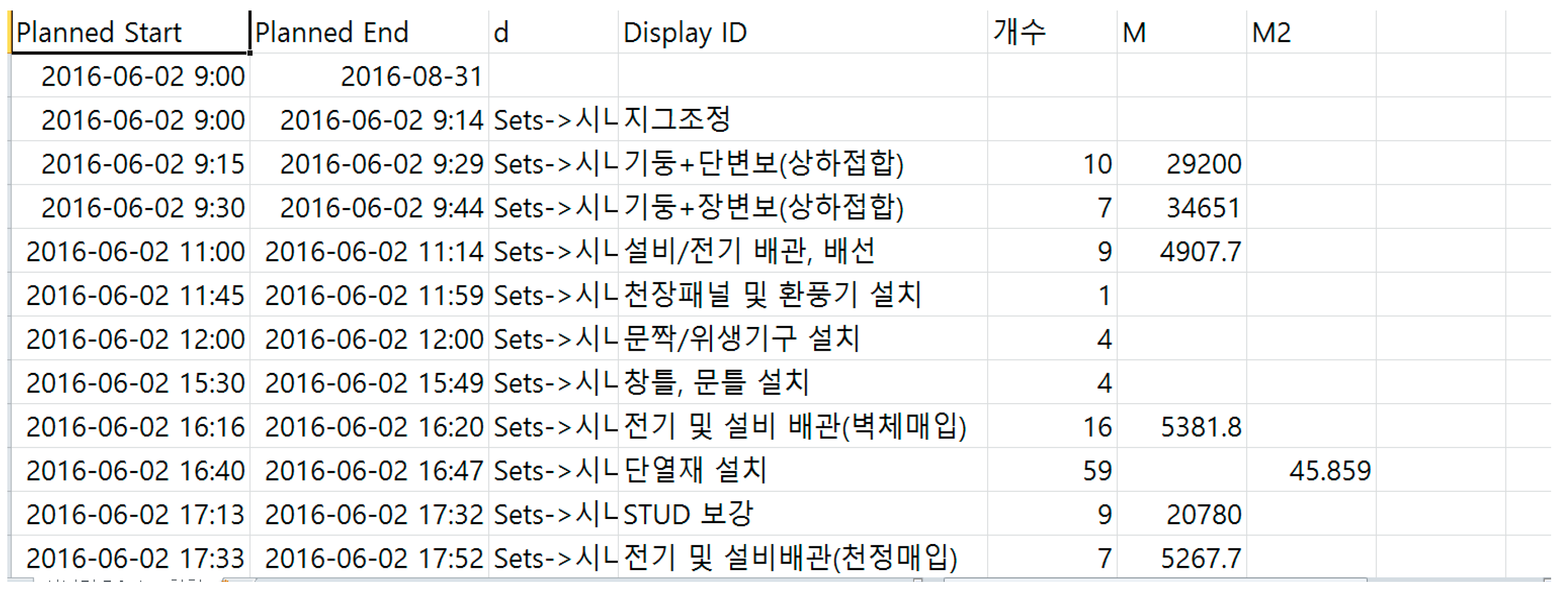
OL4MfQ: OL4M for quality.
Table 6. Detailed module manufacturing process mapping values.
Process DescriptionStart DateEnd Date
Jig adjustment2 June 2016 9:002 June 2016 9:14
Column + short span beam (combined upper and lower)2 June 2016 9:152 June 2016 9:29
Column + long span beam (combined upper and lower)2 June 2016 9:302 June 2016 9:44
Join wall braces2 June 2016 9:452 June 2016 9:59
Check vertical and horizontal measurements2 June 2016 10:002 June 2016 10:14
Modular movement (large)2 June 2016 10:152 June 2016 10:32
Stud installation on PC2 June 2016 10:332 June 2016 10:44
---------
Table 7. Information type and contents contained in operation level 4D models.
Information TypeIncluded Information
Case ProjectOL4MfSOL4MfMOL4MfQ
3D viewFloor×∆ (user setting)∆ (user setting)∆ (user setting)
Section×∆ (user setting)∆ (user setting)∆ (user setting)
Elevation×∆ (user setting)∆ (user setting)∆ (user setting)
Detail×∆ (user setting)∆ (user setting)∆ (user setting)
Factory/equipment module link view×
Expanded view according to part×
ProcessSequence○ (simple process order)○ (detailed process order)○ (detailed process order)○ (detailed process order)
S.D/F.D×○ (determined from daily work reports)○ (determined from daily work reports)○ (determined from daily work reports)
Factory layout information∆ (1 layout of a 2D floor plan)○ (factory model link)○ (factory model link)○ (factory model link)
Equipment use plan model×○ (equipment model link)○ (equipment model link)○ (equipment model link)
Other plan models×○ (yard storage and crane operating plan)○ (yard storage and crane operating plan)○ (yard storage and crane operating plan)
Material quantityTotal material quantity∆ (material quantity calculated from drawings)∆ (drawing production material quantity)
Material quantity according to work type××
Material quantity according to part being manufactured××○ (BOM and 4D model link)○ (table and 4D model link)
QualityDesign informationDrawing information○ (2D drawing)○ (2D drawing)○ (2D drawing)
Measurement information○ (2D drawing)○ (2D drawing)○ (2D drawing)
Drawing-model quality×××○ (visual check)
○ indicates that case project or OL4M frameworks can deduct new information newly created, ∆ indicates that case project or OL4M frameworks can deduct only the information based on input data, and × indicates that case project or OL4M frameworks can’t deduct new information.
Table 8. OL4M’s modeling tasks and data structures.
CategoryDescription
OL4MfSOL4MfMOL4MfQ
Time required for modeling and 4D model creation tasks
  • Total 81 h
  • Module model: Total 48 h
  • Factory model: Total 24 h
    -
    Template setting: 1 h
    -
    Revit family creation: 4 h
    -
    Factory modeling: 16 h
    -
    Interference review: 3 h
  • 4D modeling: Total 9 h
    -
    Module-factory interference review: 1 h
    -
    Schedule mapping: 6 h
    -
    4D simulation creation: 2 h
  • Total 82 h
  • Module model: Total 48 h
  • Factory model: Total 24 h
  • 4D modeling: Total 10 h
    -
    Module-factory interference review: 1 h
    -
    BOM production and link: 1 h
    -
    Schedule mapping: 6 h
    -
    4D simulation creation: 2 h
  • Total 88 h
  • Module model: Total 48 h
  • Factory model: Total 24 h
  • Drawing editing: 3 h
  • 4D modeling: Total 13 h
    -
    Module-factory interference review: 1 h
    -
    Model drawing link: 2 h
    -
    Module-drawing consistency review: 1 h
    -
    BOM production and link: 1 h
    -
    Schedule mapping: 6 h
    -
    4D simulation creation: 2 h
Additional time-1 h (compared to 81 h for OL4MfS)6 h (compared to 82 h for OL4MfM)
Personnel investment1 highly skilled technician1 highly skilled technician1 highly skilled technician
Model data structureFile structureRevit modelModule.rvtModule.rvtKayang Complex module.rvt
Module factory.rvtModule factory.rvtModule factory.rvt
4D modelOL4MfS-detail.nwd (parts 1–10)OL4MfM-total.nwdOL4MfQ-total.nwd
OL4MfS-open storage.nwdOL4MfM-detail.nwd (parts 1–10)OL4MfQ-detail.nwd (parts 1–10)
Object countTotal object count: N (module objects: n; factory and equipment objects: m)
Work typeModule: Interior finishing, structure, MEPFactory: Architecture, structure, equipment
LODModule: LOD 400; factory/equipment: LOD 200
LinkO:S = N:1 (N ≥ 1)
Processes56 (200% increase compared to 28 for AL4M)
Table 9. Mean value of clarity, appropriateness, expressiveness and effectiveness of proposed OL4M frameworks (technical review questionnaires and responses).
AspectsQuestionnaireOL4M for ScheduleOL4M for QuantityOL4M for Quality
Clarity of model structureEase of construction and operability of the 4D models3.733.853.83
Modifiability to deal with data errors or design changes3.473.613.55
Manageability of the files used to create the 4D model (original BIM model files and 4D model file)3.883.793.74
Appropriateness and expressiveness of 4D plan modelsDetailed description of schedule information and relationship with other entities3.923.763.89
Exact expression of manufacturing scene (including module schedule, material, equipment and detailed schedule)3.903.813.93
Expressiveness of presenting traditional information synthetically3.873.693.95
Effectiveness for manufacturing productivityTime saved in preparing documentation such as drawings, schedule, BOM, and reports, etc.3.423.583.31
Reduction in repetition, mistakes, and manufacturing errors3.743.823.88
Minimizing time needed to acquire information for particular tasks3.633.713.68
On a scale of: 1: strongly disagree, 2: disagree, 3: agree, 4: strongly agree.

