1. Introduction
Base isolation systems have been early introduced in the construction field so as to reduce structural damage caused by strong earthquake events, and typically represented by lead-rubber bearing (LRB) isolators [
1,
2,
3]. These LRB isolators are installed with an intention to separate main structures from below ground, and accordingly can appease seismic force by supplying extra flexibility to base columns [
3,
4,
5]. They prevent entire member damage from severe ground motion as decreasing transferred accelerations with an intention to extend the vibration period of the supporting structure. The base isolation systems passively cope with seismic motion because they can allow displacement along the direction of the earthquake event. In spite of many advantages, the use of base isolation systems has been restricted to low-to-midrise buildings rather than high-rise buildings in that base isolators installed have to uphold entire gravity loads at the sub-parts [
6,
7,
8,
9]. Contrarily, bracing members utilized as active vibration control devices act properly even in the high-rise building. It is possible to repair the frame building subjected to severe seismic loading when only damaged bracing members are replaced with new ones [
10,
11,
12]. However, once shear failure occurs at the base isolators, we will have no choice but to rebuild entire buildings due to rapid degradation in serviceability [
13,
14,
15,
16]. As modern civil structures become gradually more massive and larger and with increasing occurrence of earthquake events, scientists and engineers have been progressively increasing recognition about the improvement of the base isolation system for wide application.
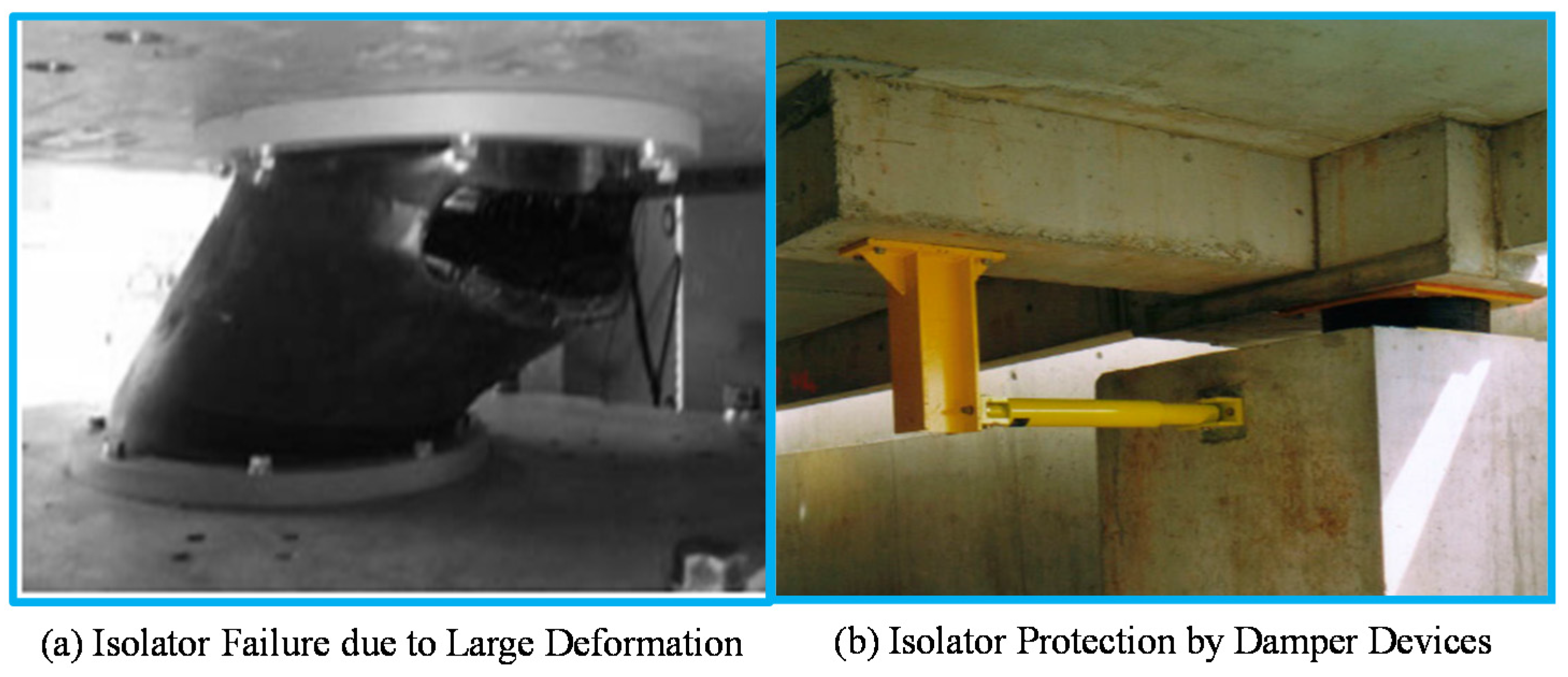
Figure 1a shows shear failure that occurs at the LRB isolator exceeding allowable lateral displacement while
Figure 1b presents the LRB isolator that is combined in parallel with the damper device used to protect its shear failure. This damper device avoids the failure of the base LRB isolator by adding additional resistance against lateral loading as well as by generating supplemental damping [
13,
15,
16]. Although damper devices used for reinforcing are impaired by strong excitation, damaged base isolation systems can be easily repaired to replace them with new ones. Owing to the characteristics of the replaceable structural fuse, the damper devices assembled to the base isolation system are encouraged to possess both energy dissipation capacity attributed to large hysteretic loop area and recentering capability attributed to small permanent deformation. Superelastic shape memory alloys (SMAs) that satisfy these requirement conditions have been recently receiving more attention to their application to the damper systems [
17,
18,
19,
20].
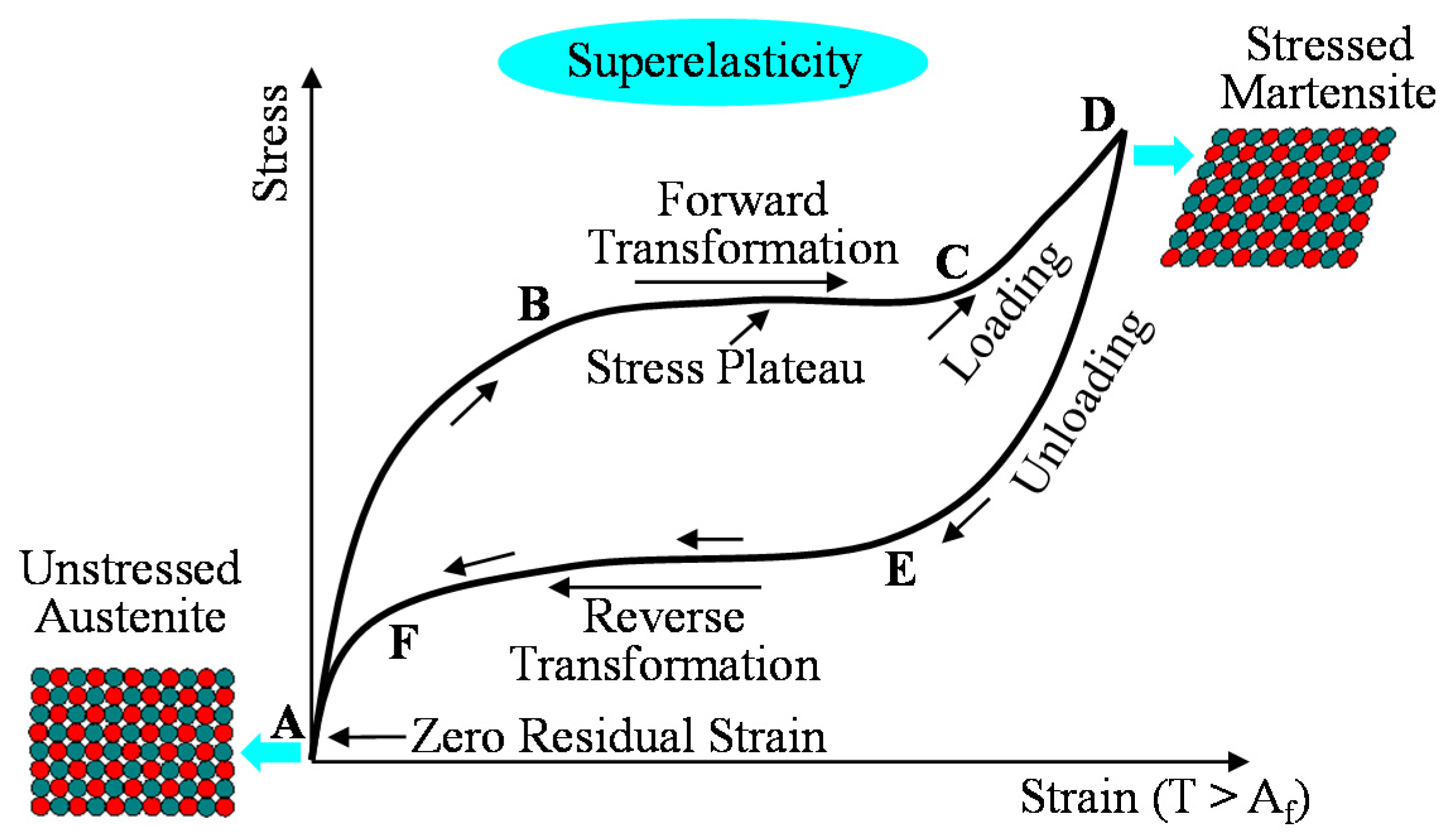
Figure 2 shows the typical stress-strain curve for superelastic SMA materials. The most commonly used SMAs referred to as Nitinol (nickel-titanium) alloys are composed of 56% nickel by weight and 44% titanium [
21]. Above the austenite finishing temperature (Af), SMA materials exhibit superelasticity which goes back to their original configuration upon unloading without any heat treatment [
19,
20,
21]. The flag-shaped hysteresis loop with a stress plateau is able to dissipate a considerable amount of energy during cyclic loads, meaning that it takes advantage of absorbing vibrations. Furthermore, this behavior displays nearly zero residual strain only after stress removal.
Figure 1.
Failure configuration and existing protection methodology of base LRB isolators.
Figure 1.
Failure configuration and existing protection methodology of base LRB isolators.
For these reasons, new base isolation systems that consist of the LRB isolator and the damper devices are proposed in this study. In other words, superelastic SMA bending bars acting as the reinforced and recentering damper are placed around the LRB isolator. Thereafter, concentrically braced frame (CBF) buildings are designed by installing these new base isolation systems at the column bases. The proposed LRB isolation systems with superelastic SMA bending bars are modeled as nonlinear component springs, and assigned to 2D frame models used for reproducing their seismic responses in the CBF building. The nonlinear dynamic time-history analyses are performed by directly imposing near-fault (NF) ground motions, which contain a narrow-banded pulse of the strong spectral acceleration at the short vibration period, on the 2D frame models [
22,
23]. The LRB base isolator systems with and without steel bending bars are also designed to conduct comparative study. Based on the analysis results, seismic responses in terms of maximum displacements, residual deformations, and recentering ratios are compared to each other for the purpose of verifying a high-performance of the proposed isolation systems.
Figure 2.
Behavior of superelastic SMA materials.
Figure 2.
Behavior of superelastic SMA materials.
2. Modeling of Base Isolation Systems
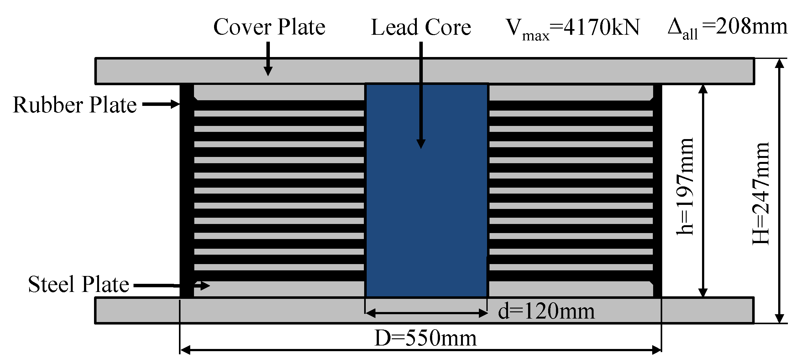
The typical LRB isolator consists of an elastomer made by laminated rubber layers with steel plates, cover plates, and a lead core placed on its center. As shown in
Figure 3, the LRB isolator presented herein was designed with 120 mm lead core diameter (d), 550 mm elastomer diameter (D), 197 mm elastomer height (h), and 247 mm total height (H). It can withstand the maximum vertical load (V
max) of 4170 kN and the allowable lateral displacement (Δ
all) of 208 mm. This LRB isolator simply regulates the amount of supplemental damping attributed by energy dissipation capacity by adjusting the diameter of the lead core. The energy dissipation provided by the yielding of the lead core allows to achieve an equivalent viscous damping coefficient up to about 30%, thereby reducing the horizontal isolator displacement effectively [
1,
2,
24]. However, the supplemental damping at the base isolation system does not guarantee a better performance of the superstructure, which can reduce inter-story drifts in all cases, especially for the low-rise building structures with relatively short periods [
25]. In addition to damping, high vertical stiffness is obtained by thin layers of rubber reinforced with steel shim plates. These characteristics permit the LRB isolator to move laterally with relative lower stiffness than other isolation system, but carry significant axial load owing to its high vertical stiffness. The LRB isolators are usually circular in shape.
Figure 3.
Typical lead-rubber bearing (LRB) model.
Figure 3.
Typical lead-rubber bearing (LRB) model.
The typical hysteresis loop of the LRB isolator can be modelled as the bilinear curve. As shown in
Figure 4, the bilinear curve for the LRB isolator used in this study is simulated using four design parameters such as F1, Δ1, F2, and Δ2. The elastic stiffness (K
e) and the post-yield stiffness (K
p) are also expressed using these design parameters as follows:
Figure 4.
Hysteretic behavior of the LRB model.
Figure 4.
Hysteretic behavior of the LRB model.
The effective stiffness of the hysteresis loop (
Keff) is defined as the secant line indicating the ratio of force to displacement as follows:
The characteristic strength located on a force-axis intercept at the zero displacement (Q) can be represented by the equation with the post-yield stiffness as follows:
The amount of energy dissipation, which can be characterized by the area of the hysteresis loop, is defined as the following equation.
The effective viscous damping coefficient is derived using the amount of energy dissipation and the effective stiffness, and defined as the following equation. This damping coefficient can be rewrote as the equation expressed with four parameters.
As can be seen in Equation 6, the effective viscous damping coefficient is proportional to the amount of energy dissipation, but inversely related to the effective stiffness and the square of the specific displacement.
3. Concept of Recentering Base Isolation Devices
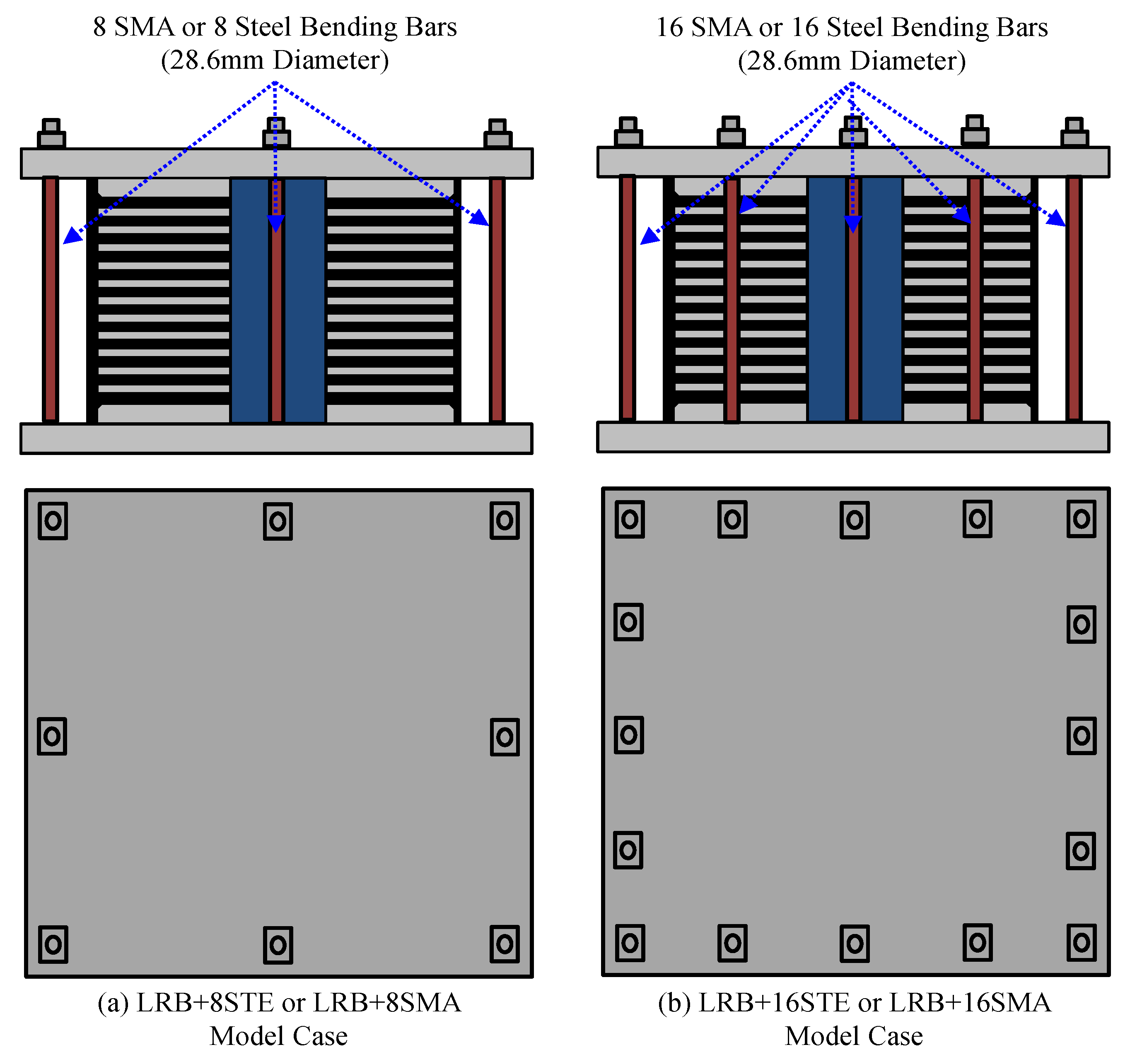
The superelastic SMA bending bars are equipped to the LRB isolators for the purpose of providing more resistance against shear force and recentering capability to the base isolation system.
Figure 5 shows the LRB isolators with superelastic SMA (
i.e., LRB+8SMA and LRB+16SMA models) bending bars, which are suggested in this study. The integrated SMA bending bars make a contribution to decreasing permanent deformation. The LRB isolators combined with steel bending bars (
i.e., LRB+8STE and LRB+16STE models) are also presented so as to compare each seismic performance. The steel or SMA bending bars are constructed in circular shape with 28.6 mm diameter. Although these bending bars can effectively decrease maximum displacement occurring at the base isolator, they may cause to shorten the vibration period of the entire structure due to reinforcing effect. The superelastic SMA materials are more flexible than the steel materials, and so diminish slightly structure’s vibration period as compared to the usage of only LRB isolator. Furthermore, their flag-shaped hysteresis behavior not only dissipates considerable amount of kinetic energy but also reduces permanent deformation attributed to recentering force. In this study, their unique characteristics are taken into consideration for the design of smart base isolation systems. The superelastic SMA bending bars are connected to the LRB isolator by using nuts instead of welding in order to avoid phase transformation caused by heat treatment.
Figure 5.
LRB models with bending bars used for seismic restrainers.
Figure 5.
LRB models with bending bars used for seismic restrainers.
Figure 6.
Response mechanism of the self-centering LRB isolator.
Figure 6.
Response mechanism of the self-centering LRB isolator.
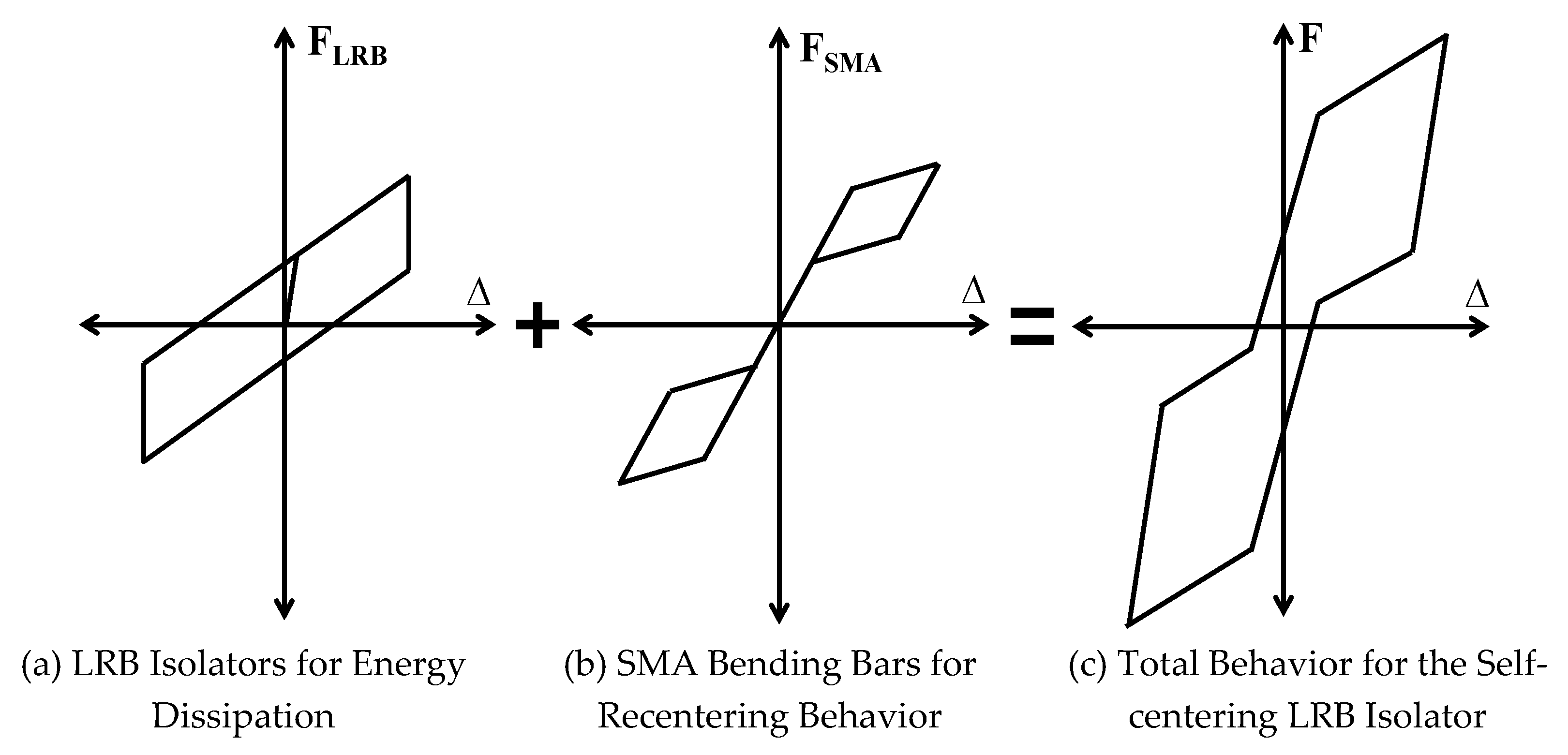
The behavioral mechanism of the recentering base isolation system, which is simulated by assembling individual components (
i.e., LRB base isolator and superelastic SMA bending bars), is presented in
Figure 6. Stable energy dissipation can be obtained from the behavior of the LRB isolator, which is characterized by the hysteresis loop with hardening as shown in
Figure 6a. In spite of having excellent damping capacity attributed to this energy dissipation, it is prone to generating residual displacement during cyclic loads. The behavior of the superelastic bending bars, which stands for the flag-shaped hysteresis loop, compensates this problem with recentering force generated upon unloading (see
Figure 6b). The mechanism of the recentering LRB base isolation system can be formulated by assembling two component mechanisms in parallel, and therefore reinforcing as well as recentering is simultaneously expected in this system as presented in
Figure 6c. The force-displacement mechanism for simulating the behavior of the assembled system is defined as follows:
These mechanisms are modelled as a series of lines for stiffness models used for simulating the behavior of the base isolation system.
4. Prototype Frame Buildings
All frame models were designed according to the current design codes [
26,
27] in an effort to investigate the performance of the base isolation system equipped in the concentrically braced frame (CBF) building subjected to earthquake loading. They were assumed to be 2D frame structures because of symmetric configuration. The basic conditions for design, including dead and live load (DL and LL), are summarized in
Table 1. The prototype frame buildings were constructed to satisfy design limits under the design-based earthquake (DBE) level. The 2D nonlinear pushover analyses with equivalent lateral loads were conducted to verify the adequacy of initial frame design. The sizes of brace, beam, and column members were designed in accordance with the AISC-LRFD steel design manual [
28]. The sizes of the individual members were adjusted until maximum inter-story drift ratios meet less than 2% allowable limit. These prototype frame buildings are assumed to be located on the high-seismicity LA area. The stability check was also conducted with stability limits.
Table 1.
Basic design conditions.
Table 1.
Basic design conditions.
| Located Area | Loads (Other) | Loads (Roof) | SDC | Site Condition | Occupancy Category |
|---|
| LA Area | DL: 4.12 kPa
LL: 2.39 kPa | DL: 4.50 kPa
LL: 0.96 kPa | D Class | Stiff Soil (Class D) | Ordinary Structures |
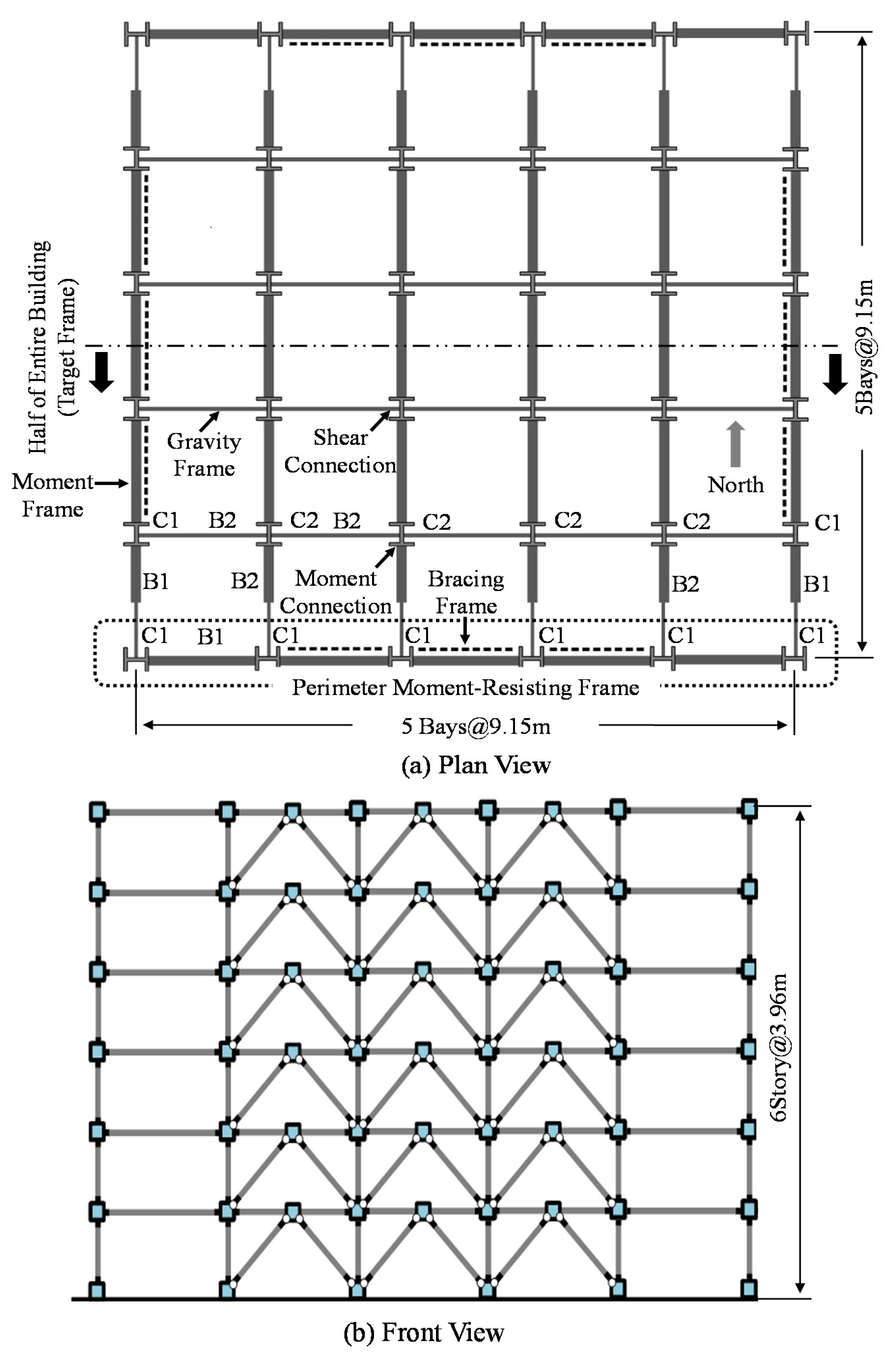
The prototype frame buildings were constructed as 6-story steel frame structures with perimeter moment-resisting CBFs to resist wind and earthquake loads as shown in
Figure 7. Owing to a symmetric plan with 9.25 m square bays (see
Figure 7a), essentially regular condition without in-plane torsional effect can be taken into consideration for design and analysis. Masses and stiffnesses are uniformly distributed over each floor. All of the CBF buildings have 3.96m story heights (see
Figure 7b). The inverted V-braced frame systems were accepted among several CBF types, and symmetrically installed on each side. The perimeter bays with braced frame systems are denoted as dashed lines in the plan view. In the plan view, the moment-resisting frames illustrated as the thick lines were constructed with the welded connections that can mostly transfer moment from beam to column. On the other hand, the gravity load-resisting frames in the building inside were built with the pinned connections that only transfer shear force. Uniform column sections were applied to frame design throughout all floors while smaller beam sections were assigned to higher floors. The assigned member sizes are summarized in
Table 2.
Figure 7.
Design of the concentrically braced frame (CBF) building.
Figure 7.
Design of the concentrically braced frame (CBF) building.
Table 2.
Details of the member sizes.
Table 2.
Details of the member sizes.
| Story | Column* (C1) | Beam* (B1) | CBF** | Int. Column* (C2) | Int. Beam* (B2) |
|---|
| 1 | W14 × 109 | W24 × 84 | HSS6 × 6 × 3/8 | W12 × 87 | W24 × 68 |
| 2 | W14 × 109 | W24 × 84 | HSS6 × 6 × 3/8 | W12 × 87 | W24 × 68 |
| 2 | W14 × 109 | W24 × 68 | HSS6 × 6 × 3/8 | W12 × 87 | W24 × 68 |
| 3 | W14 × 109 | W24 × 68 | HSS6 × 6 × 3/8 | W12 × 87 | W24 × 68 |
| 4 | W14 × 109 | W18 × 50 | HSS6 × 6 × 1/4 | W12 × 87 | W24 × 68 |
| 5 | W14 × 109 | W18 × 50 | HSS6 × 6 × 1/4 | W12 × 87 | W24 × 68 |
5. Analytical Modeling and Tests
Including nonlinear component springs used for reproducing the behavior of the base isolation system, detailed procedures for creating analytical frame models are mainly described in this section. The OpenSEES program developed by Mazzoni
et al. [
29] was used to create analytical models as well as to conduct nonlinear time-history dynamic analyses. The nonlinear material properties were modelled as a series of the lines referred as to the stiffness models, and assigned to the corresponding components composing the base isolation system. The behavior of the steel bending bars fabricated with Gr. 50 carbon steel was reproduced by using the uniaxial steel material model provided in the OpenSEES program. The stress and strain curve for Gr. 50 carbon steel was composed of a yield stress (F
y) of 345 MPa, an elastic modulus (E) of 200 GPa, and a hardening ratio of 1.5%. Due to absence of adequate default materials models provided in the OpenSEES program, user-defined material (UMAT) models based on Aurrichio’s subroutine codes were employed to simulate the behavior of the superelastic SMA materials [
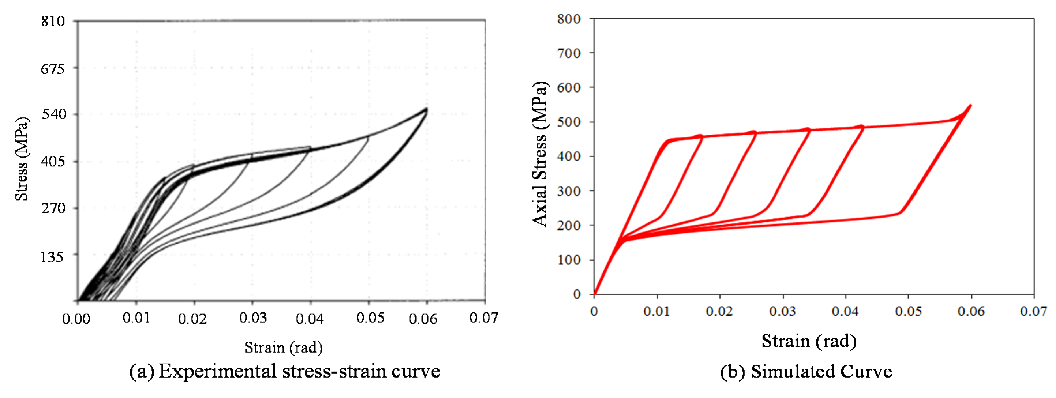
30]. The phase transformations are expressed in this UMAT model by using martensitic volume fractions during cyclic loading. The necessary parameters used as the input values for formulating the flag-shaped hysteresis loop in the UMAT model are obtained from the uniaxial pull-out tests under isothermal conditions. As seen in
Figure 8, the simulated stress and strain curve for the superelastic SMA was calibrated to the experimental test result. The required input parameters such as elastic modulus (40 GPa), Poisson’s ratio (0.33), martensite start stress (440 MPa), martensite finish stress (540 MPa), austenite start stress (250 MPa), austenite finish stress (140 MPa), and transformation strain (0.042), phase transformation temperature (22 °C)) were acquired from uniaxial pull-out tests conducted by DesRoches
et al. [
19], and used for this numerical simulation.
Figure 8.
Stress and strain curves for superelastic Nitinol SMA materials.
Figure 8.
Stress and strain curves for superelastic Nitinol SMA materials.
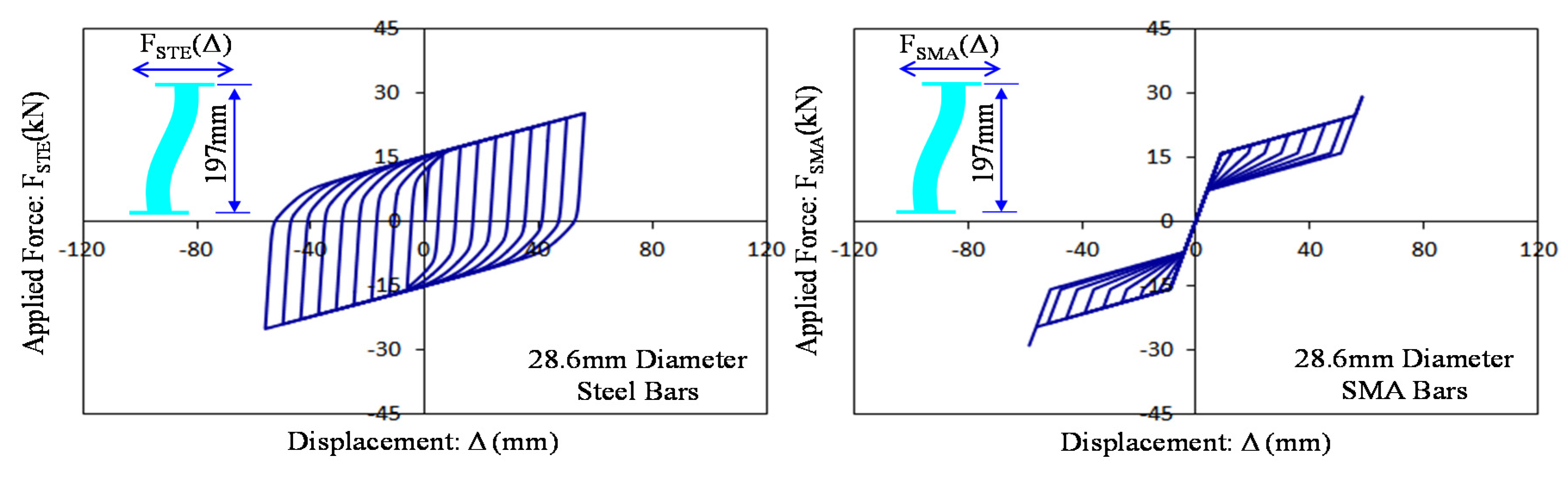
The steel and SMA bending bars are assumed to be fixed-end supported beams subjected to transverse shear force. The force and displacement curves for the fixed-end supported bending bars are simulated by numerical analyses conducted on component springs with the material models mentioned above, and presented in
Figure 9. It can be shown that these force and displacement curves are directly affected by the behavior of the used materials. The cyclic behavior of the steel bending bars can be represented by the isotropic hardening material while that of the superelastic SMA bending bars coincides with the flag-shaped hysteresis loop. The post-yield strength of the superelastic SMA bending bars is larger than that of the steel bending bars owing to their material properties. The adequacy of the UMAT model to simulate the behavior of superelastic SMA materials was verified by previous research [
30,
31]. These steel and SMA bending bars in the LRB base isolation system are modeled as nonlinear component springs combined with corresponding uniaxial material properties.
Figure 9.
Simulated force and displacement curves for fixed-end supported bars under bending.
Figure 9.
Simulated force and displacement curves for fixed-end supported bars under bending.
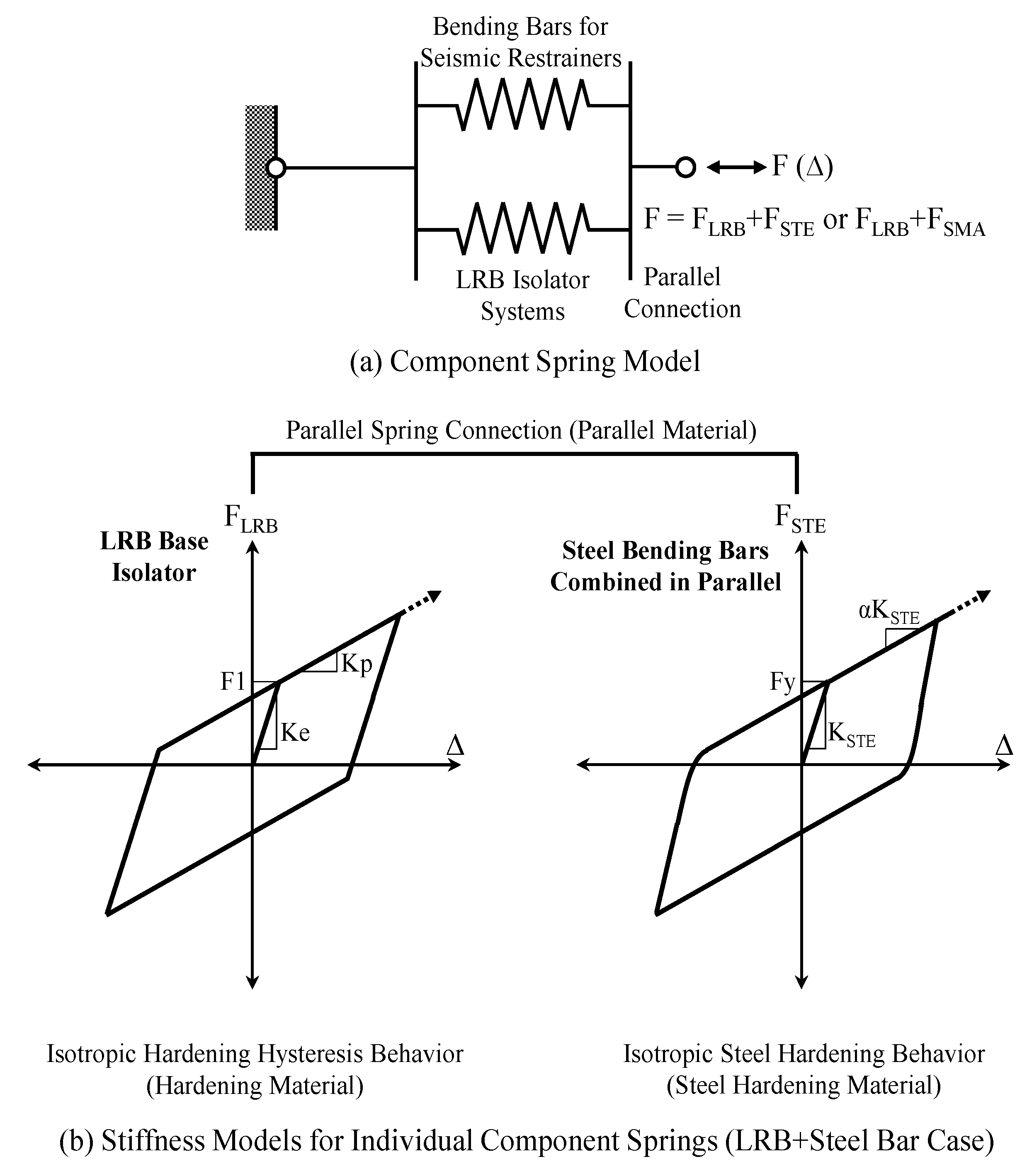
The assemblage of individual component springs with their hysteresis behavior is illustrated in
Figure 10. They can be assembled in parallel according to the consideration of force transfer (see
Figure 10a). The force and displacement hysteresis curves that stand for the behavior of individual component springs were simulated by multi-linear stiffness models as shown in
Figure 10b,c. Initial stiffness (
i.e., K
e and K
STE), yield force (
i.e., F
1 and F
y), and tangential stiffness (
i.e., K
p and αK
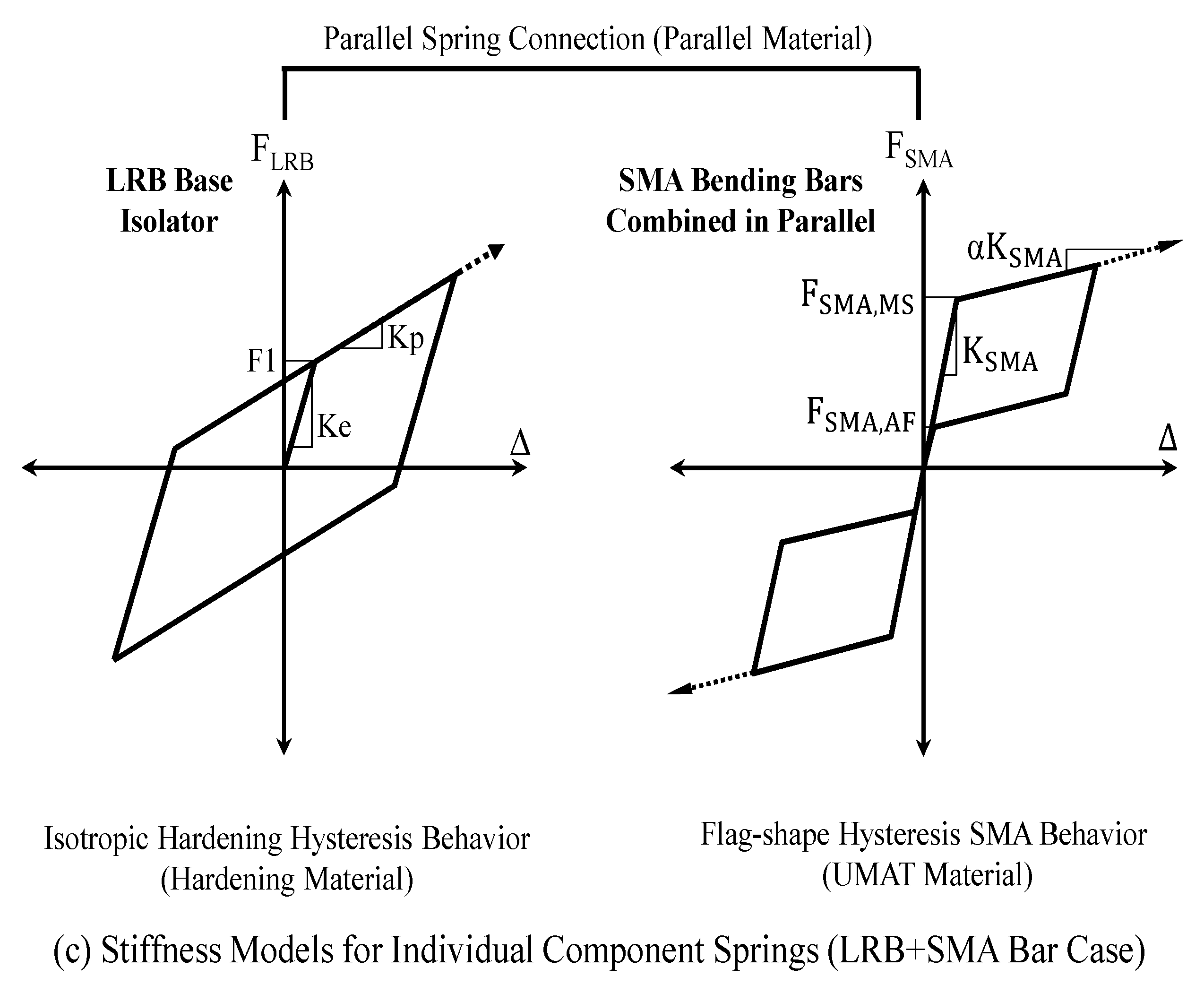
STE) result in three main parameters required to simulate the behavior of LRB isolators and steel bending bars. These hysteresis curves were activated by using hardening material commands provided in the OpenSEES program. In contrast, initial stiffness (K
SMA), martensite phase transformation starting force (F
SMA,MS), martensite phase transformation ending force (F
SMA,MF), austenite phase transformation starting force (F
SMA,AS), austenite phase transformation ending force (F
SMA,AF), strain hardening ratio (α), and phase transformation distance (Δ
L) are necessary to simulate the behavior of superelastic SMA bending bars by using UMAT subroutine codes. In addition to material properties, effective viscous damping coefficients were assigned to LRB component springs by utilizing the Rayleigh damping command given in the OpenSEES program.
Figure 10.
Assemblage of component springs used for numerical analyses.
Figure 10.
Assemblage of component springs used for numerical analyses.
The behaviors of LRB isolators and bending bars, which are simulated by corresponding component springs, are presented in
Figure 11 and
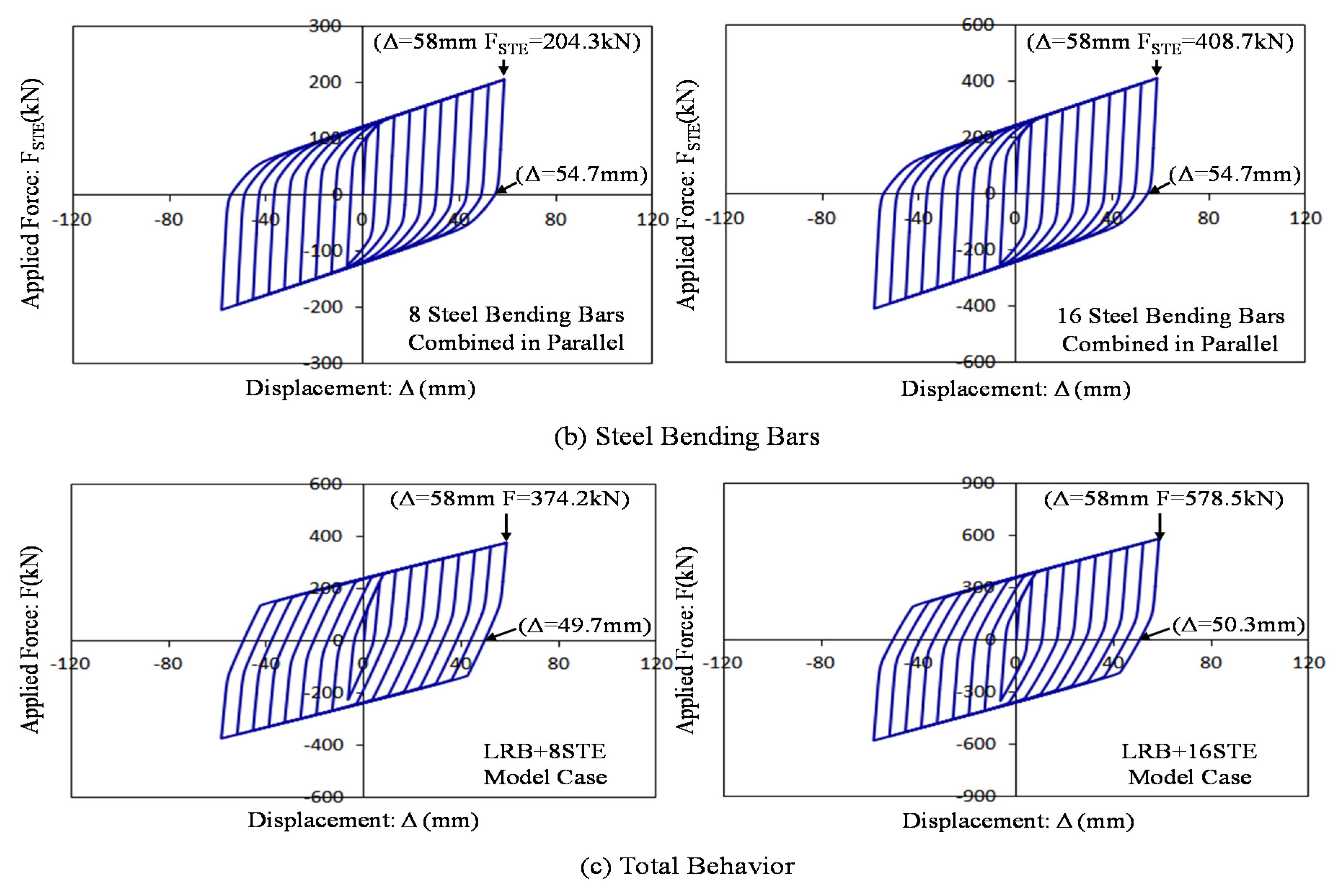
Figure 12. As we expected, all of component behaviors coincide with stiffness models assigned to component springs. Isotropic hardening idealized by the bilinear curve is observed at the behavior of LRB isolators and steel bending bars cyclically simulated. The flag-shaped hysteresis curves which display symmetric shape in tension and compression are founded at the behavior of the superelastic SMA bending bars. The component springs for the LRB isolators reach 169.8 kN at the displacement of 58 mm. They can only recover elastic deformation upon unloading, and thus remain residual displacement such as 47.5 mm from the maximum displacement of 58 mm. Similarly, component springs for the assembled steel bending bars behave as the same manner, and remains a lot of residual displacement as well. It can be shown in
Figure 11c that the behavior of the LRB isolation system with steel bending bars can meet the force-displacement mechanism for the parallel assemblage given to Equations (7) and (8). In addition to reinforcing effect, the superelastic SMA bending bars provide recentering force to the assembled LRB isolation system. As the number of SMA bars installed increase, the occurrence of residual displacement gradually decrease owing to augmenting recentering force ratios (
i.e., F
SMA,AF/F1). For instance, the LRB+8SMA frame model with eight SMA bending bars exhibits 28.5 mm residual displacement at the last loading step while the LRB+16SMA frame model with sixteen SMA bending bars has only 5.4 mm residual displacement under the same loading step. The assembled component springs were installed to 2D frame models used for nonlinear dynamic time-history analyses.
Figure 11.
Simulated behaviors for the LRB isolator system and steel bending bars.
Figure 11.
Simulated behaviors for the LRB isolator system and steel bending bars.
Figure 12.
Simulated behaviors for the LRB isolator system and SMA bending bars.
Figure 12.
Simulated behaviors for the LRB isolator system and SMA bending bars.
Figure 13.
Modeling attributes for 2D nonlinear frame models with base isolator devices.
Figure 13.
Modeling attributes for 2D nonlinear frame models with base isolator devices.
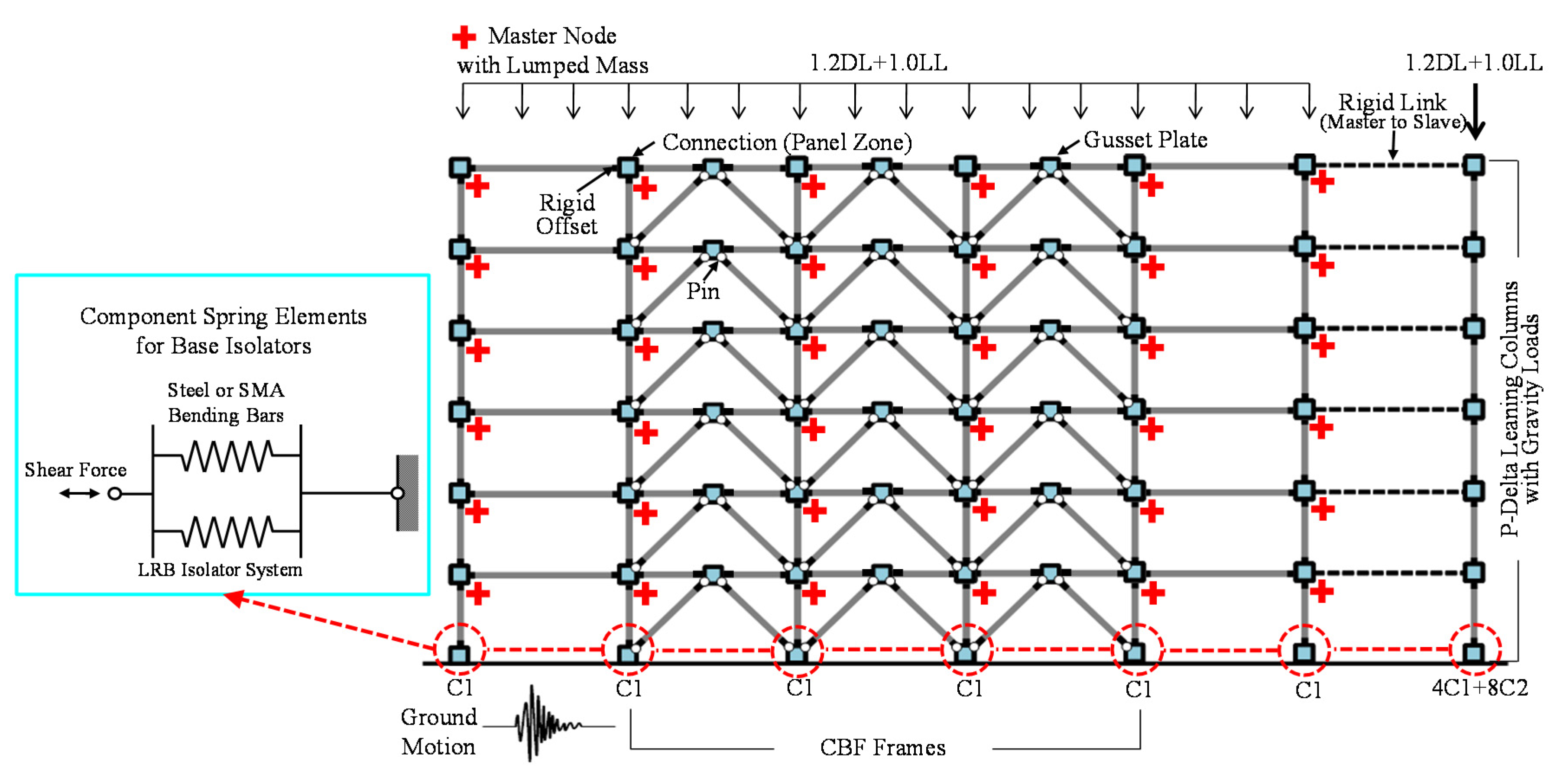
The modeling attributes for 2D frame models with base isolator devices modelled as the component springs are presented in
Figure 13. The column bases are considered to be flexible rather than fixed because of the installed base isolation systems. The main frame members (e.g., beam, column, and brace members) were constructed with nonlinear beam-column elements with 2D fiber sections able to collect stress and strain data. For the brace members allowed to buckle in compression, initial imperfection was generated by offsetting the nodal points at the mid-length of the brace member. All of main frame members fabricated with Gr. 50 carbon steel were assigned to 1.5% strain hardening and 5% Rayleigh damping coefficient. The lumped masses assigned to all of nodal points were converted from dead loads plus partial live loads in order to generate seismic shear force. The transient equilibrium based on the Newmark method was applied to the time dependent dynamic analyses. The rigid links with hinge connections were constructed with an aim to activate diaphragm constraints between two frame systems, and accordingly each floor can translate as a rigid body motion. The P-delta coordinate transformations were assigned to column members for the purpose of simulating geometric nonlinearity associated with second-order behavior. The beam-to-column connections are assumed to be rigidly welded, thereby applying rigid offsets to every beam members. For initial loading condition, the factored dead and live loads as presented in
Figure 13 were applied to 2D frame models. Finally, primary response data were collected by using recorder commands provided in the program.
6. Ground Motions
The ground motion data resulting from historic earthquake records were used for nonlinear time-history dynamic analyses. They were developed by the FEMA/SAC project [
32]. The near-fault (NF) ground motions generated from earthquake records including strike, rupture, oblique, and thrust. The magnitudes of these NF ground motions coincide with UBC Seismic Hazard Zone 4 corresponding to a seismic hazard level of 10% probability of exceedance in 50 years. The details of the used NF ground motions are given to
Table 3 including magnitude (Richter scale ranging from 6.7 to 7.4), distance from epicenter, duration time, and peak ground accelerations (PGAs). Statistical evaluations in terms of base shear forces, maximum base displacements, and residual displacements can be conducted after observing several analysis results.
Table 3.
Near-fault ground motion data used for nonlinear dynamic analyses.
Table 3.
Near-fault ground motion data used for nonlinear dynamic analyses.
| Ground Motion ID | EQ Record | Richter Scale | Distance (km) | Duration (sec) | Max PGA (g) | Min PGA (g) |
|---|
| NF01 | 1978 Tabes | 7.4 | 1.2 | 50 | 0.90 | −0.86 |
| NF02 | 1979 Tabes | 7.4 | 1.2 | 50 | 0.98 | −0.75 |
| NF03 | 1989 Loma Prieta (Los Gatos) | 7 | 3.5 | 25 | 0.72 | −0.64 |
| NF04 | 1989 Loma Prieta (Los Gatos) | 7 | 3.5 | 25 | 0.46 | −0.44 |
| NF05 | 1989 Loma Prieta (Lex Dam) | 7 | 6.3 | 40 | 0.59 | −0.69 |
| NF06 | 1989 Loma Prieta (Lex Dam) | 7 | 6.3 | 40 | 0.37 | −0.28 |
| NF07 | 1992 Mendocino | 7.1 | 8.5 | 60 | 0.64 | −0.62 |
| NF08 | 1992 Mendocino | 7.1 | 8.5 | 60 | 0.60 | −0.66 |
| NF09 | 1992 Erizincan | 6.7 | 2.0 | 21 | 0.43 | −0.31 |
| NF10 | 1992 Erizincan | 6.7 | 2.0 | 21 | 0.46 | −0.27 |
| NF11 | 1992 Landers | 7.3 | 1.1 | 50 | 0.71 | −0.71 |
| NF12 | 1992 Landers | 7.3 | 1.1 | 50 | 0.61 | −0.80 |
| NF13 | 1994 Northridge (Rinaldi) | 6.7 | 7.5 | 15 | 0.62 | −0.89 |
| NF14 | 1994 Northridge (Rinaldi) | 6.7 | 7.5 | 15 | 0.38 | −0.39 |
| NF15 | 1994 Northridge (Olive View) | 6.7 | 6.4 | 60 | 0.51 | −0.73 |
| NF16 | 1994 Northridge (Olive View) | 6.7 | 6.4 | 60 | 0.60 | −0.56 |
| NF17 | 1995 Kobe | 6.9 | 3.4 | 60 | 1.09 | −0.73 |
| NF18 | 1995 Kobe | 6.9 | 3.4 | 60 | 0.58 | −0.57 |
| NF19 | 1995 Kobe (Takatori) | 6.9 | 4.3 | 40 | 0.749 | −0.51 |
| NF20 | 1995 Kobe (Takatori) | 6.9 | 4.3 | 40 | 0.38 | −0.42 |
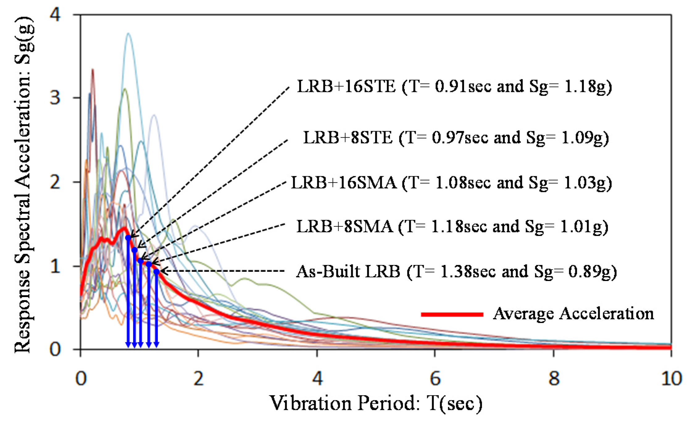
Response spectral accelerations for individual NF ground motions with 5% damping and their average spectral acceleration with 1.0 scale factor (SF) are presented in
Figure 14. In addition, vibration periods for 2D frame models, which are estimated by using the computational commend provided in the OpenSEES program, are also given to this figure. The frame structures are considered to be single degree of freedom (SDOF) systems under independent ground motions, and then the design base shear forces are simply estimated by using these spectral accelerations on their vibration periods. The vibration periods for 2D frame models are affected by the stiffness of the used LRB isolation system. Therefore, LRB isolation systems with bending bars have shorter vibration periods than as-built LRB isolation systems without bending bars. The frame models with shorter vibration periods are subjected to larger response spectral accelerations. The mean response spectral acceleration for LRB+16STE model is taken as approximately 1.18 g for 0.91 s vibration period while that for as-built LRB model is taken as about 0.89 g for 1.38 s vibration period (see
Figure 14). The LRB isolation systems with superelastic SMA bending bars are more flexible than those with steel bending bars, and thus display longer vibration periods. Although superelastic SMA bending bars acting as reinforcing and recentering devices have a tendency to increase response accelerations transferred from ground, they can effectively control maximum displacement as well as reduce residual deformation. It will be confirmed though the observation of analyses results in the next section.
Figure 14.
Spectral accelerations for near-fault ground motions and vibration time periods for individual model cases (SF = 1.0).
Figure 14.
Spectral accelerations for near-fault ground motions and vibration time periods for individual model cases (SF = 1.0).
7. Seismic Responses
The nonlinear dynamic time-history analyses were conducted on 2D frame models subjected to 20 NF ground motion data in an effort to investigate the efficiency of different LRB base isolation systems equipped in the CBF building. The seismic responses of the 2D frame models (e.g., roof displacement, base shear force, and residual deformation) are compared to each other. The resulting curves from dynamic analyses conducted with the NF11 ground motion are presented in
Figure 15. The NF11 ground motion possesses 50 s duration time with 0.71 g peak ground acceleration (PGA) which occurs around 10 s. The As-built LRB frame model exhibits larger maximum roof displacement than other frame model with bending bars because of more flexible isolation system. The maximum roof displacements for LRB+8STE and LRB+8SMA frame models subjected to the NF11 ground motion with 1.0 SF are approximately 550 mm and 350 mm, respectively while the maximum roof displacement of As-built LRB frame model is as much as 900 mm. The maximum roof displacement of each frame model occurs at the same time (about 12 s), and generally follows the generation time of PGA by 1.5 s. As can be seen in the figure, superelastic SMA bending bars effectively decrease vibration, amplitude, and maximum roof displacement. The frame model with the LRB+16SMA isolation system has the smallest maximum roof displacement among other frame models. However, there is a little discrepancy between two frame models with SMA bending bars.
Figure 15.
NF11 ground motion data used for nonlinear dynamic analyses and time vs. roof displacement curves for individual model cases.
Figure 15.
NF11 ground motion data used for nonlinear dynamic analyses and time vs. roof displacement curves for individual model cases.
The behavior of base isolation systems in the frame model is also necessary to investigate the effectiveness of these displacement control devices. The dynamic responses for individual base isolation systems subjected to the NF11 ground motion with 1.0 SF are presented in
Figure 16. In addition to time
versus displacement curves, shear force
versus displacement curves are shown in this figure. All of the frame models exhibit the almost same maximum base shear force reaching at about 600 kN, but have different maximum displacements arising due to the discrepancy of stiffness capacity. The superiority of the superelastic SMA bending bars with respect to vibration mitigation and recentering capability can be clearly identified when investigating the behavior of the isolation systems installed in the frame models. The As-built LRB frame model exceeds the limit for the allowable lateral displacement of the used LRB isolator (Δ
all = 208 mm) firstly after PGA occurrence time, meaning that this frame model undergoes the shear failure. The maximum base displacement of the LRB+8STE frame model closely approaches the allowable lateral displacement. In case of the LRB+8SMA frame model, it is shown that the superelastic SMA bending bars make a significant contribution to reducing vibration amplitude and maximum base displacement. Recentering behavior which augments recoverable displacement (
i.e., Δ − Δ
rec) begins to be displayed at the base shear force
versus displacement curve in the LRB+8SMA frame model. Furthermore, the LRB+16SMA frame model completely recovers original position without residual deformation (Δ
res). On the other hand, the LRB+16STE frame model generates a lot of residual deformation at the end of the analysis due to the yielding of the steel bending bars. It is thus verified that superelastic SMA bending bars damp vibration quickly, reduce maximum base displacement, and foster recentering capability.
Figure 16.
Dynamic responses for individual models under the NF11 ground motion (SF = 1.0).
Figure 16.
Dynamic responses for individual models under the NF11 ground motion (SF = 1.0).
8. Performance Evaluation
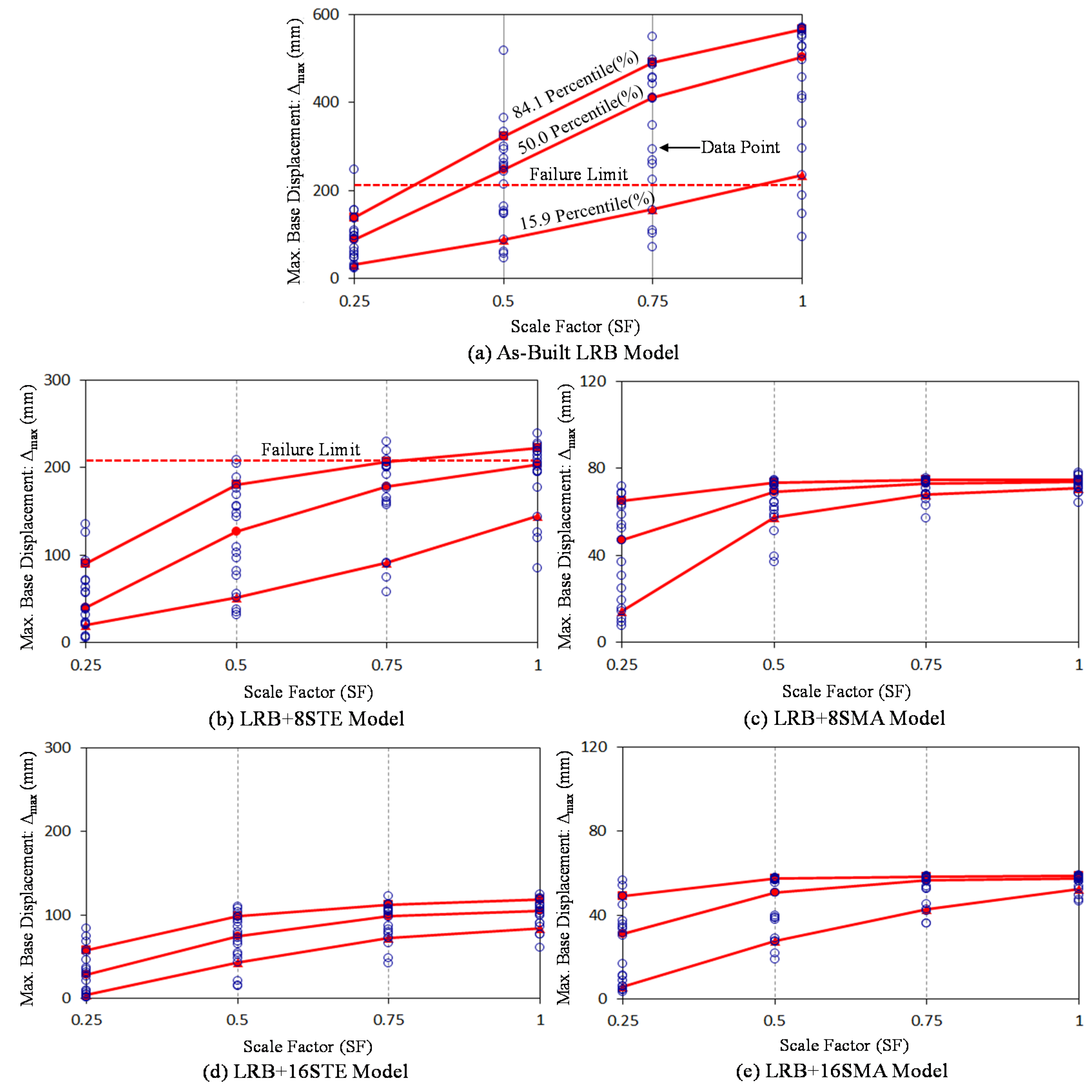
As increasing the scale factor of the ground motion (SF = 0.25, 0.50, 0.75, and 1.00), more nonlinear dynamic time-history analyses were conducted with 20 NF ground motions in order to perform statistical investigation with respect to maximum base displacement and recentering capability in the base isolation system. The maximum base displacements for individual frame models subjected to 20 NF ground motions with difference SFs are presented in
Figure 17. For statistical evaluation, the solid lines representing 15.9th, 50.0th (or median), and 84.1th percentile ranks are also presented in the graph with the individual data points obtained from all analyses. These solid lines gradually ascend according to increasing SFs. The As-built LRB frame model starts to exceed the allowable displacement limit for the shear failure of the used LRB isolators even at the time of 0.25 SF. The statistical line for 50.0th percentile rank (median line) goes over the allowable displacement limit when NF ground motions are applied to 0.5 SF. Except for three cases, the As-built LRB frame model experiences the shear failure of the LRB isolators subjected to NF ground motions with 1.0 SF. The LRB+8STE frame model begins to undergo the shear failure of the LRB isolators when SF exceeds the value of 0.5. On the contrary, base isolation systems with superelastic SMA bending bars are safe against NF ground motions when considering maximum base displacements less than allowable displacement limits. As the magnitude of ground motions increases, the range of data scatter indicating the extent of uncertainty decreases. The data points converge to the certain level around at the 1.0 SF, thereby guaranteeing the reliability of seismic performance under strong earthquake events.
Figure 17.
Maximum base shear displacements (Δmax) under seismic ground motions.
Figure 17.
Maximum base shear displacements (Δmax) under seismic ground motions.
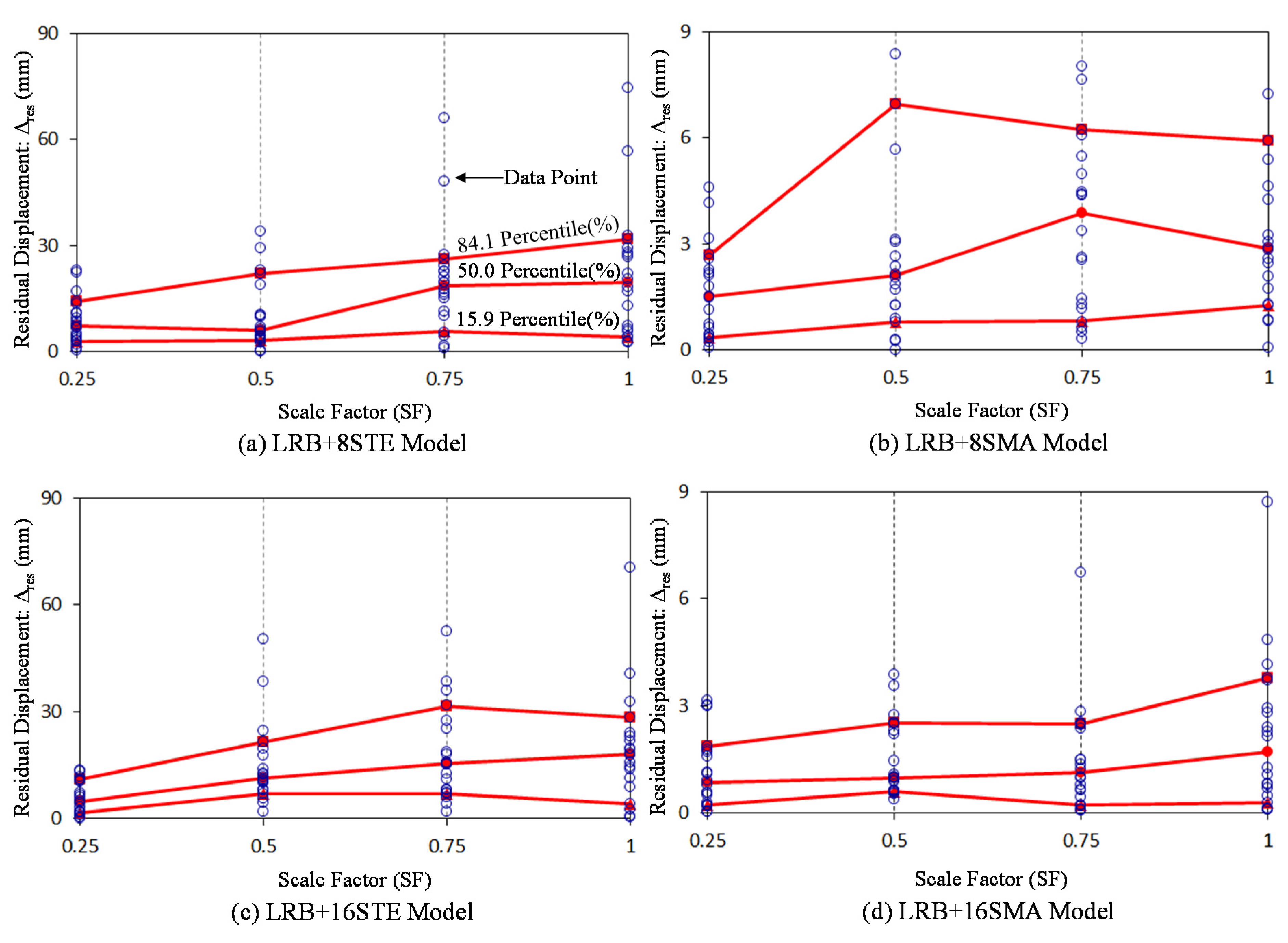
Except for the As-built LRB frame model, residual displacements that may happen due to the yielding of bending bars are necessary to investigate the effectiveness of the recentering device in the proposed base isolation system. The residual base shear displacements (Δ
res) under seismic ground motions are measured at the end of the analyses, and presented in
Figure 18. In general, base isolation systems with steel bending bars exhibit ten times larger residual displacements than those with superelastic SMA bending bars. For 50th percentile (median) rank, the LRB+16STE frame model possesses approximately 15 mm residual displacement while the LRB+16SMA frame model generates about 1.5 mm residual displacement at most. The LRB+16STE frame model has the statistical lines placed to slightly higher levels as compared to the LRB+8STE frame model under the same percentile rank. On the contrary, the LRB+16SMA frame model occupies the lower level of the statistical lines under the same percentile rank than the LRB+8SMA frame model. It is, therefore, concluded that superelastic SMA bending bars help base isolation systems to reduce residual displacement.
Figure 18.
Residual base shear displacements (Δres) under seismic ground motions.
Figure 18.
Residual base shear displacements (Δres) under seismic ground motions.
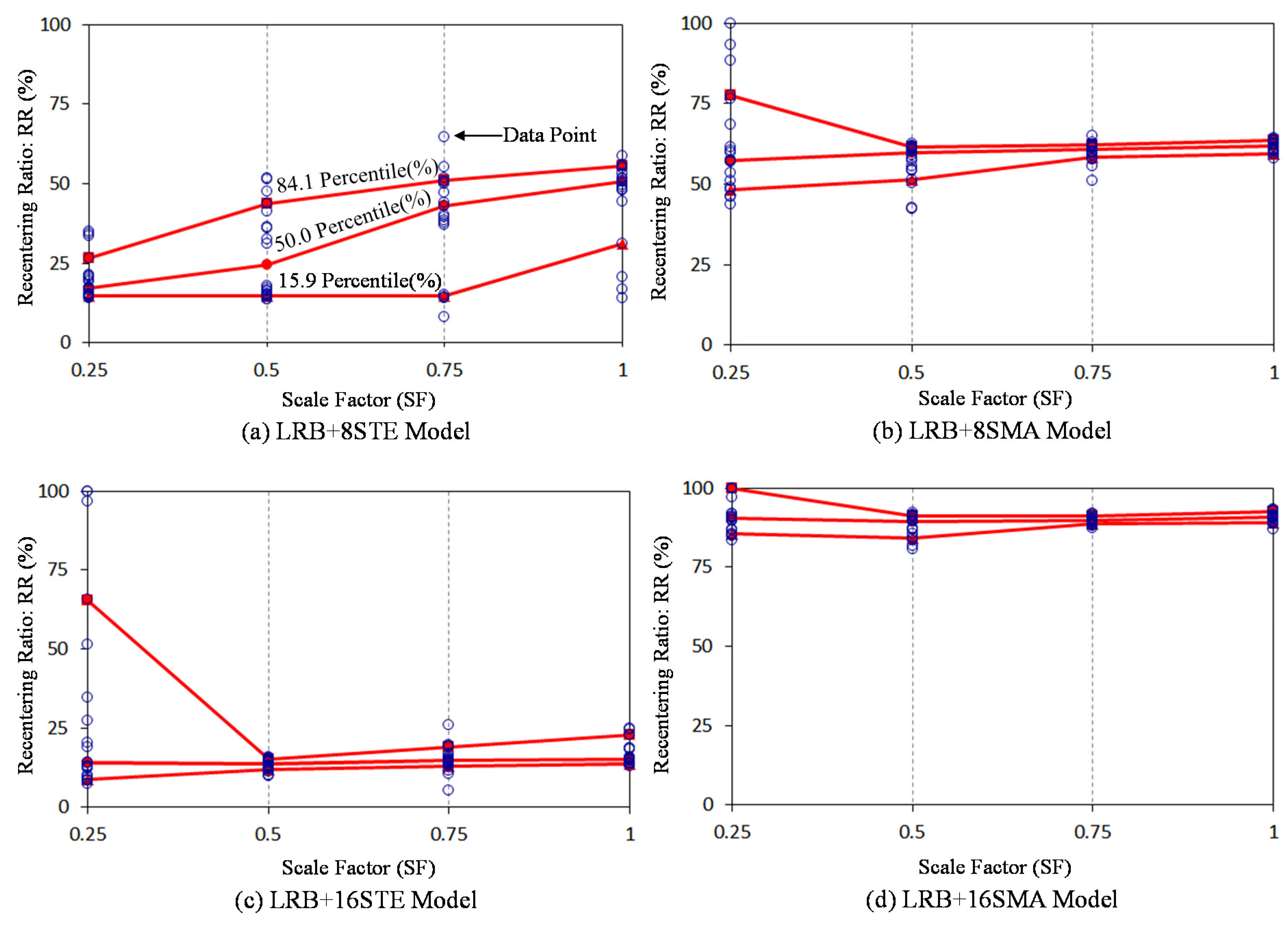
For another examination, recentering ratios (RRs) are needed to be investigated so as to evaluate the recentering capability of individual base isolation systems. They are defined as the ratio of the maximum recoverable displacement to the maximum displacement, and expressed as the percentile index as follows:
The recentering ratios (RRs) under seismic ground motions with increasing SFs are presented in
Figure 19. The RRs of the LRB+16STE frame model are mostly distributed below 25%. As compared to the RRs of the LRB+8STE frame model, the usage of more steel bending bars deteriorates all the more recentering capability in spite of reducing maximum displacement. Although more kinematic energy can be dissipated by the yielding of the steel bending bars, this mechanism give rise to the decrease of recoverable displacement during earthquake loading. The median line of the LRB+8SMA frame model maintains the constant level above the RR of 60% regardless of increasing SFs. In particular, the LRB+16 frame model displays the median line placed to the level greater than the RR of approximately 90%, meaning that this model perfectly recovers its original configuration. The analysis results such as maximum displacements, residual displacements, and RRs are summarized in
Table 4. It can be finally shown that superelastic SMA bending bars play a role in recentering as well as reinforcing very well in the base isolation system.
Figure 19.
Recentering ratios (RRs) under seismic ground motions.
Figure 19.
Recentering ratios (RRs) under seismic ground motions.
Table 4.
Summary of nonlinear dynamic analysis results.
Table 4.
Summary of nonlinear dynamic analysis results.
| Evaluation Item | Model ID | SF=0.25 | SF=0.50 | SF=0.75 | SF=1.00 |
|---|
| 15.9% | 50.0% | 84.1% | Mean | SD | 15.9% | 50.0% | 84.1% | Mean | SD | 15.9% | 50.0% | 84.1% | Mean | SD | 15.9% | 50.0% | 84.1% | Mean | SD |
|---|
| Δmax (mm) | LRB | 31.6 | 89.2 | 138.9 | 90.3 | 55.1 | 89.3 | 248.4 | 323.1 | 224.9 | 115.9 | 156.6 | 409.9 | 489.3 | 354.7 | 151.4 | 235.2 | 503.0 | 566.4 | 429.3 | 152.7 |
| LRB+8STE | 20.3 | 39.5 | 90.1 | 50.9 | 36.9 | 51.6 | 126.6 | 179.9 | 120.3 | 58.1 | 91.5 | 177.8 | 206.2 | 166.8 | 50.0 | 144.2 | 202.8 | 222.4 | 190.9 | 39.9 |
| LRB+8SMA | 14.3 | 47.1 | 64.8 | 41.4 | 22.2 | 57.3 | 69.1 | 73.3 | 64.4 | 10.8 | 67.7 | 73.1 | 74.4 | 70.4 | 4.8 | 70.7 | 73.8 | 74.8 | 72.9 | 3.1 |
| LRB+16STE | 4.3 | 28.0 | 57.5 | 30.4 | 25.7 | 43.63 | 74.8 | 98.5 | 70.1 | 29.4 | 72.1 | 98.9 | 112.0 | 90.6 | 22.4 | 84.4 | 104.5 | 118.6 | 101.1 | 16.7 |
| LRB+16SMA | 5.8 | 30.9 | 48.9 | 26.4 | 18.1 | 27.8 | 50.6 | 57.4 | 44.8 | 13.4 | 42.8 | 56.6 | 58.3 | 52.4 | 7.6 | 52.2 | 57.4 | 58.6 | 55.8 | 3.8 |
| Δres (mm) | LRB+8STE | 2.8 | 7.3 | 14.1 | 8.7 | 6.4 | 3.2 | 6.2 | 22.0 | 10.3 | 9.6 | 5.6 | 18.5 | 26.0 | 20.1 | 15.2 | 4.2 | 19.4 | 31.7 | 21.5 | 18.0 |
| LRB+8SMA | 0.4 | 1.5 | 2.7 | 1.6 | 1.3 | 0.8 | 2.1 | 6.9 | 3.2 | 3.1 | 0.8 | 3.9 | 6.2 | 3.7 | 2.9 | 1.3 | 2.9 | 5.9 | 3.7 | 3.0 |
| LRB+16STE | 1.6 | 4.9 | 11.2 | 5.8 | 4.4 | 7.0 | 11.3 | 21.3 | 14.9 | 11.4 | 7.1 | 15.4 | 31.6 | 18.0 | 13.3 | 4.2 | 17.8 | 28.2 | 19.4 | 15.5 |
| LRB+16SMA | 0.2 | 0.9 | 1.9 | 1.1 | 1.0 | 0.6 | 1.0 | 2.5 | 1.5 | 1.0 | 0.2 | 1.1 | 2.5 | 1.5 | 1.5 | 0.3 | 1.7 | 3.8 | 2.2 | 2.1 |
| RR (%) | LRB+8STE | 14.6 | 17.3 | 26.5 | 20.2 | 6.7 | 14.7 | 24.5 | 43.7 | 28.5 | 13.9 | 14.9 | 43.0 | 50.9 | 39.6 | 15.4 | 31.2 | 50.7 | 55.5 | 45.8 | 13.3 |
| LRB+8SMA | 48.4 | 57.3 | 77.4 | 62.6 | 15.9 | 51.3 | 59.7 | 61.5 | 56.9 | 5.9 | 58.2 | 60.7 | 62.3 | 59.9 | 2.8 | 56.4 | 61.7 | 63.6 | 61.5 | 1.7 |
| LRB+16STE | 8.8 | 14.0 | 65.5 | 31.7 | 31.9 | 11.9 | 13.8 | 15.0 | 13.4 | 1.7 | 12.9 | 14.6 | 19.0 | 15.0 | 4.0 | 13.7 | 15.2 | 22.8 | 17.1 | 3.8 |
| LRB+16SMA | 85.7 | 90.5 | 100.0 | 91.7 | 5.6 | 84.3 | 89.3 | 91.3 | 87.9 | 3.5 | 88.6 | 89.9 | 91.1 | 89.9 | 1.3 | 88.9 | 90.7 | 92.4 | 90.6 | 1.6 |


