1. Introduction
One of the most active research fields in acoustics is noise reduction, for which innovative materials are continuously proposed and investigated. Improving the sound insulation performance of a building façade or of a road barrier is very important in order to protect people from the surrounding noise, and much work has been done in this direction. In particular, low frequency industrial noise [
1] and traffic noise [
2,
3,
4] are recognized to be a real problem that has strong negative impacts on citizens’ health and wellness [
5,
6,
7,
8].
Traditionally, to achieve significant sound insulation properties, devices made of spongy, porous materials, made from an expanded matrix or made of fibers are used (expanded polystyrene, expanded polyurethane, mineral wool, glass wool). The limitation with traditional sound insulators is that these materials are visually opaque, not flexible and, consequently, they cannot be used for several applications. Furthermore, conventional materials are effective at medium-high frequencies, while low-frequency noise reduction requires massive structures, and therefore high costs and thicknesses, according to the well-known mass law [
9].
Recent research on the improvement of the insulating properties of structures has been directed to the introduction of new acoustic materials. In the class of new construction materials, geopolymer foam concrete has been studied for its thermal properties and to achieve low-frequency insulation [
10]. Sustainable natural and recycled materials have been proposed to improve over traditional materials’ performances in sound insulation [
11,
12,
13]. Green barriers have shown to provide an interesting way to improve the quality of life in urban environments: in [
14], the use of a green wall was evaluated as a passive acoustic insulation system for buildings.
In this context, acoustic metamaterials can represent a significant source of innovation. Metamaterials are the subject of an ever-increasing amount of research efforts in different branches of physics and engineering, focusing on their possible exploitation for a wide range of unprecedented applications [
15,
16,
17,
18,
19,
20,
21,
22]. Using properly designed metamaterials, it is possible to improve the performances of existing devices or to overcome a few limitations connected with the use of natural materials, by building composite structures whose properties may fall in unusual ranges. Metamaterials were first conceived in electromagnetics [
23,
24,
25,
26], but recent advances have proved that they can also be applied in acoustics [
27,
28,
29,
30]. Many research efforts in acoustic applications have been devoted to the possibility of hiding an object, the so-called cloaking, both by means of transformation acoustics [
29,
31,
32,
33,
34] and through scattering cancellation [
35,
36,
37]. Beyond these applications, the aim of the present study is to investigate the possibility of controlling sound transmission thanks to acoustics metamaterials, which have shown to be promising for also improving acoustic insulation. For this application, they are usually realized as membrane-type acoustic structures, also known as locally-resonant sonic materials, and they are essentially based on an array of elastic resonators composed of a heavy core surrounded by a soft coating layer [
27,
38]. The main limitation of such an approach is represented by the difficulties in its practical realization, which led to a limited applicability.
In this work, the possibility of employing very simple metamaterials-inspired surfaces composed by acoustically small inclusions is investigated. The geometric properties of such structures directly affect their reflection and transmission coefficients, which can be tailored by acting on the effective acoustic impedance of the metasurface. This behavior is dependent on the frequency of the impinging pressure wave and can be modified, to some extent, by varying distances and dimensions of the inclusions.
A few works investigating possible implementations of this approach recently appeared in the literature: metasurfaces based on subwavelength gratings and controlled variable fillings have been proposed for flexible control of transmission and reflection of acoustic waves [
39]; very effective acoustic absorbers constituted by subwavelength arrays of bubbles were analyzed in [
40,
41]. The structure designed in this paper is somewhat similar to the ones shown in the latter references, but is intended for airborne applications, rather than for underwater ones, and is an acoustic metasurface composed of air spheres or cylinders immersed in a water matrix. These materials have been chosen for constructing a model system that can approximate several couples of sustainable and/or innovative isotropic materials (such as, e.g., air and paraffin or rubber, aerogel and hydrogel); these kinds of materials also have the advantage of being transparent to light, differently from conventional sound insulation materials which are opaque. . The focus is on a low-frequency range (
f < 1000 Hz) that is the most critical region to treat with conventional sound insulators; full-wave simulations were performed to investigate the actual frequency range in which the transmitted acoustic field can be significantly reduced compared to the case of using homogeneous layers.
It is worth stressing that, in the effort of employing sustainable materials, characterized by low impacts and reduced embodied energy, acoustic metamaterials are particularly promising because their properties and the operation frequency band do not depend in a critical way on the material, but they mainly rely on geometrical shapes, dimensions, and distances of the inclusions.
2. Methods
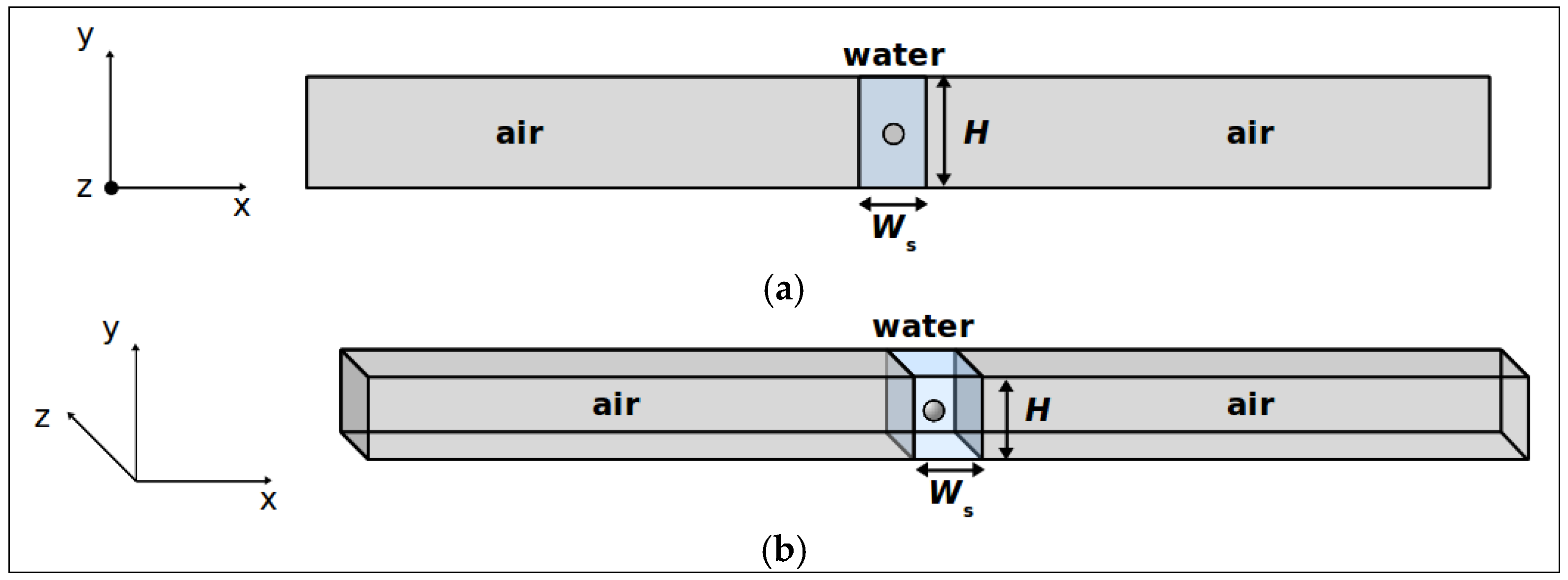
Two different kinds of metasurfaces were studied by means of full-wave simulations, based on the finite-element method as implemented in the software COMSOL Multiphysics: a two-dimensional (2D) configuration (
Figure 1a), consisting in a water layer of thickness
Ws, embedding an array of infinite air cylinders, with relative distance
H, and a three-dimensional (3D) geometry (
Figure 1b), in which the inclusions are a 2D array of air spheres. In all cases, both the radius of the cylinders or of the spheres and their relative distances are much smaller than the wavelength of operation. Physics-controlled, extremely fine, predefined meshes were used. Floquet periodic boundary conditions have been employed: in the 2D configuration, characterized by cylindrical inclusions, the structure is periodically repeated along the
Y-axis and is infinitely extended along the
Z-axis, whereas in the 3D configuration, where spherical inclusions are considered, the structure is periodical both along the
Y-axis and the
Z-axis. A single-frequency plane-wave pressure field propagates along the
X-axis and through the metasurfaces, which were characterized through their transmission and reflection coefficients. Both normal and oblique incidences were addressed. The linear wave equation was solved assuming fluid media and no losses. A plane wave radiation condition was used at the right edge of the systems to avoid artificial reflections from the boundary. Checks of the results in the known cases of normal and oblique incidence of plane waves on homogeneous layers were performed.
Figure 1.
(a) Geometry of the problem for the metasurface with cylindrical inclusions; (b) Geometry of the problem for the metasurface with spherical inclusions. A periodic-boundary conditions scheme is assumed, which means that only the unit cells are displayed in the figures.
Figure 1.
(a) Geometry of the problem for the metasurface with cylindrical inclusions; (b) Geometry of the problem for the metasurface with spherical inclusions. A periodic-boundary conditions scheme is assumed, which means that only the unit cells are displayed in the figures.
In the 3D geometry, a first approximation of the first resonance frequency of the structure can be obtained by means of the Minnaert model [
42] which provides the resonance frequency
of a gas bubble in water:
where
is the sphere radius,
is the polytropic coefficient of the gas in the bubble,
is ambient pressure and
is water density.
3. Results and Discussion
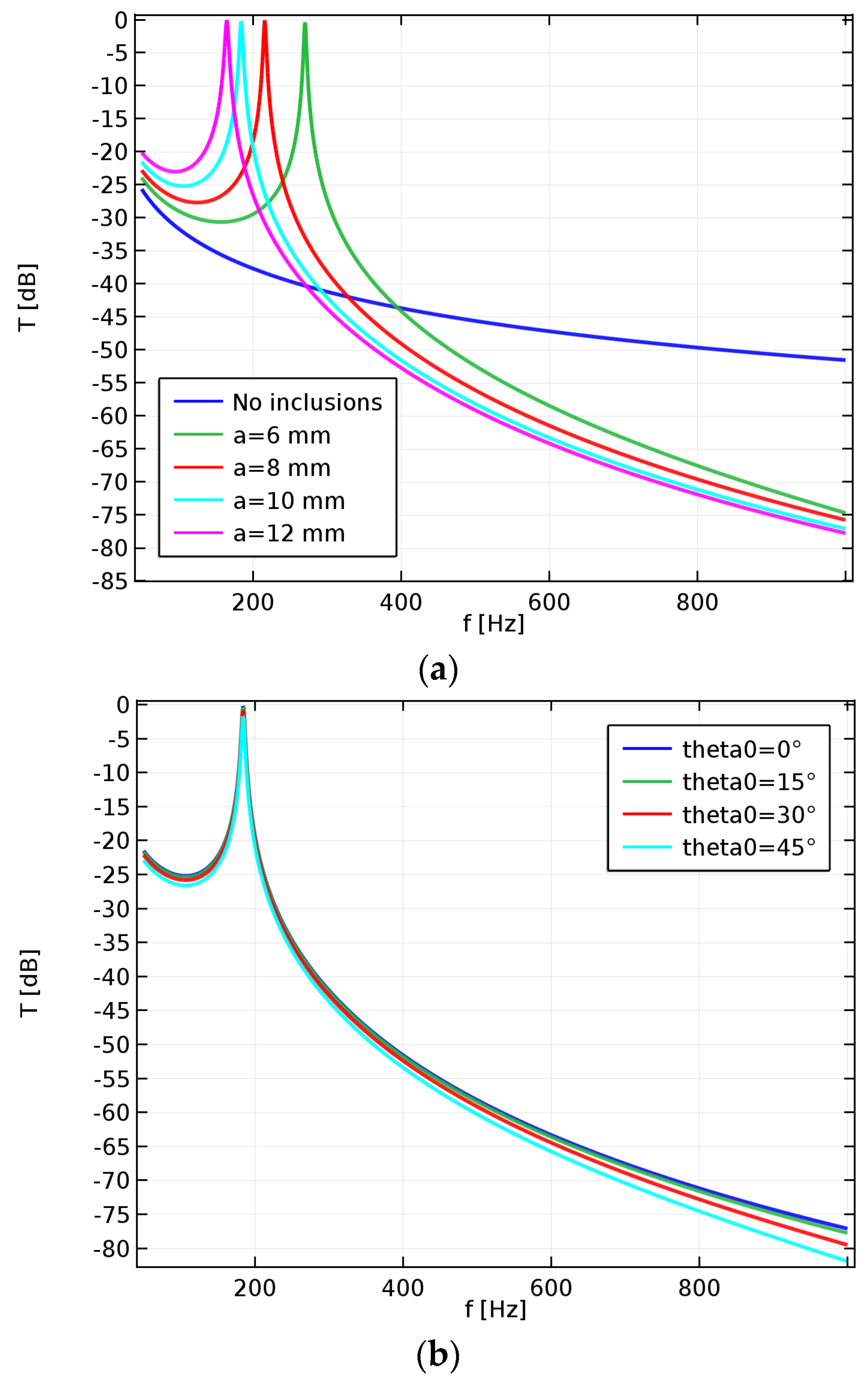
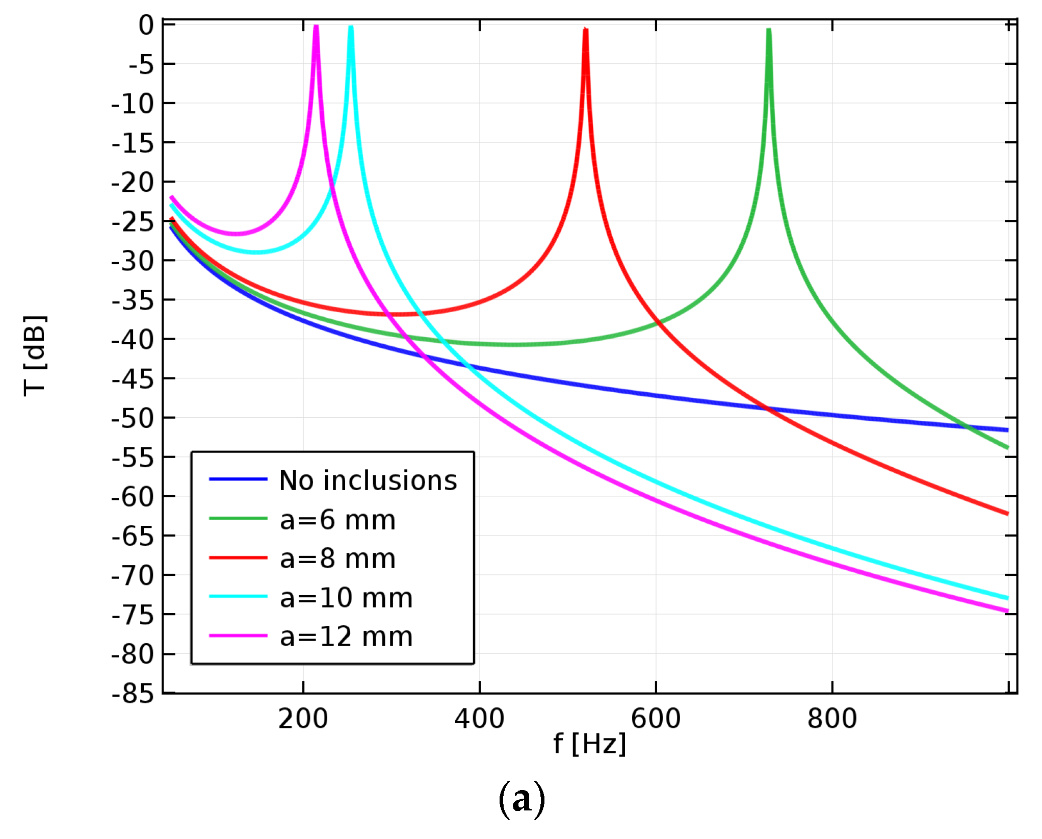
Starting with the 2D configurations, we analyzed the behavior of an array of cylinders with relative distance H = 2.5 cm, immersed in a water layer with thickness Ws = 5 cm.
Figure 2a shows the modulus of the transmission coefficient of such structures, defined as
T =
Pt/
Pi where
Pi is the complex amplitude of the incident acoustic pressure and
Pt is the transmitted one,
versus the frequency for a few values of the radius
a of the cylinders. For comparison, the transmission coefficient of a uniform water layer is also reported in
Figure 2a. The analysis of the behavior of the two types of structures reveals that, although at very low frequencies the metasurface yields a higher transmission than the uniform layer, and even total transmission at the resonance of the structure, beyond the resonance peak it allows a significant reduction of the pressure level, compared to the one obtainable with a homogeneous layer. The position of this peak depends on the radius
a of the cylinders and can be moved to lower frequencies by increasing this parameter. In the shown example, the lowest frequency above which the use of the metasurface proves to be advantageous ranges between 270 and 390 Hz. The effect of the incidence angle on the modulus of the transmission coefficient is reported in
Figure 2b, showing a remarkable stability of the metasurface behavior with respect to this parameter, correlated with the subwavelength thickness of the structure.
Figure 2.
Modulus of the transmission coefficient of an array of air cylinders in a water matrix (H = 2.5 cm): (a) variable cylinders’ radius and normal incidence; (b) variable incidence angle and radius a = 10 mm.
Figure 2.
Modulus of the transmission coefficient of an array of air cylinders in a water matrix (H = 2.5 cm): (a) variable cylinders’ radius and normal incidence; (b) variable incidence angle and radius a = 10 mm.
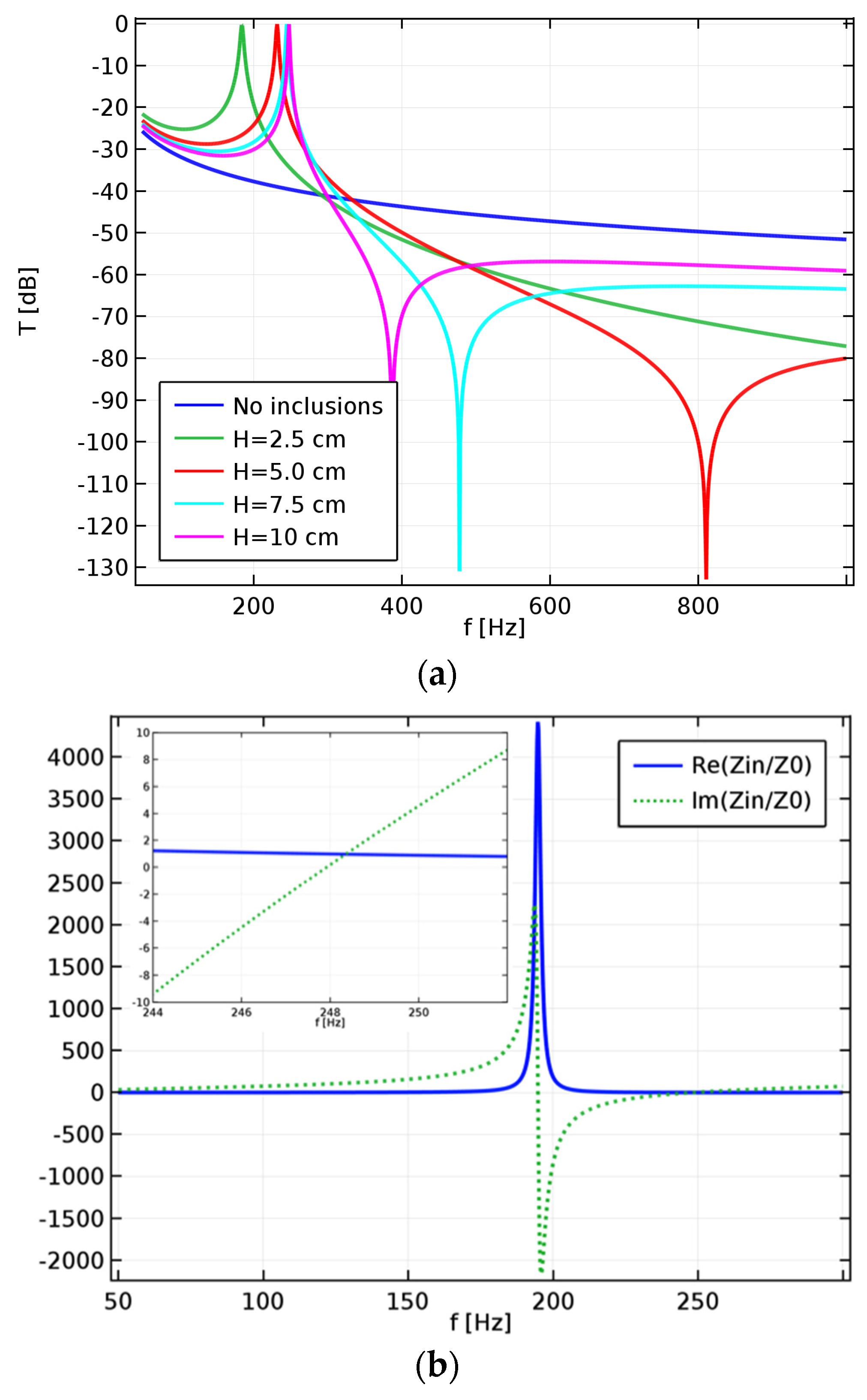
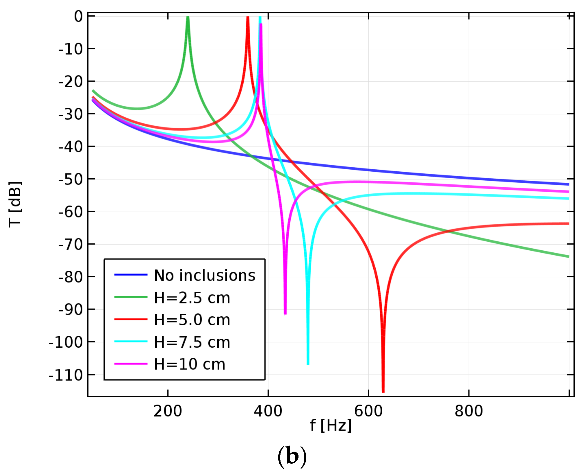
The other parameter that can be tuned to move the resonance peak of the structure is the distance
H between the cylinders.
Figure 3a,b display the modulus of the transmission coefficient for structures with
a = 10 mm and different values of
H. Increasing the value of this parameter shifts the frequency peak to higher values. However, also the shape of the transmission coefficient versus the frequency changes with
H so that this parameter has only a minor effect on the lowest frequency at which the metasurface exhibits a lower transmission than a homogeneous layer. Instead, the parameter
H has a significant influence on the bandwidth in which a desired rejection level can be achieved, with smaller values of
H providing wider bandwidths. To summarize, large values of
a and small values of
H would be necessary to provide effective sound insulation at lower frequencies and over extended frequency bands.
A minimum of the reflection coefficient (not shown) occurs at the resonance peak and almost complete reflection of the pressure field outside resonance is observed. A similar behavior was recently theoretically and numerically predicted for an acoustic metasurface based on subwavelength slits [
39]. Once the complex reflection coefficient is known, the input impedance seen by the impinging pressure field can be calculated through a retrieval procedure as
[
43]. The plots in
Figure 3b show the real and imaginary part of the normalized impedance for the structure with
H = 10 cm. As shown in the inset, at the resonance frequency (
= 248 Hz), the real part of the normalized impedance is 1, leading to a good matching with air and an almost complete transmission. Before resonance, the real part of the normalized impedance exhibits a large peak, corresponding to the maximum mismatch in the low-frequency region.
Figure 3.
(a) Modulus of the transmission coefficient of an array of air cylinders in a water matrix (a=10 mm) with variable distance H between cylinders. (b) Real and imaginary parts of the normalized input impedance of an array of air cylinders in a water matrix (a = 10 mm, H = 10 cm). The inset shows a zoom of the resonance region.
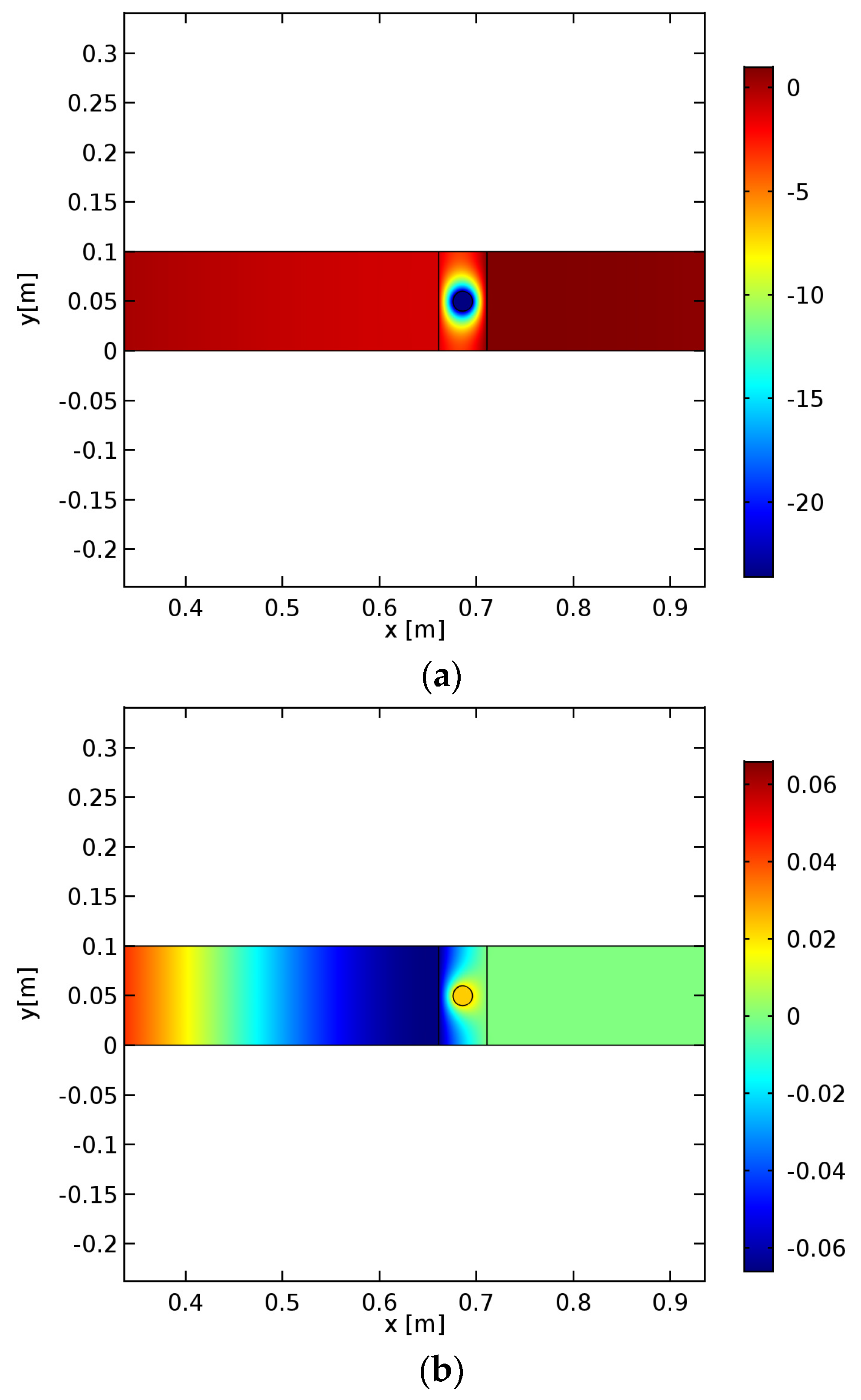
Snapshots of the total pressure fields obtained at the resonance and antiresonace frequencies are shown in
Figure 4: it can be appreciated how the pressure field, which impinges from the left with an amplitude of 1 Pa, is totally transmitted at the resonance frequency, at which constructive interference builds a large pressure field inside the metasurface, whereas at the antiresonance frequency it tends to zero after the metasurface.
Moving to the 3D configurations, it is now the radius a of the air spheres that controls the resonance frequency above which there is a large low-transmission band. The approximate value of the bubble resonance frequency can be predicted by the Minnaert model if the spheres are not too close: the absolute error in the resonance frequency can be estimated to be within 5% for distances H among the spheres larger than 10a. It has to be noticed, anyway, that the resonance frequency is also influenced by the finite thickness of the water layer.
Figure 4.
Pressure field at the resonance frequency f = 248 Hz (a) and at the antiresonance f = 387 Hz (b) for the structure with H = 10 cm and a = 10 mm. Colorbars indicate the pressure in Pa.
Figure 4.
Pressure field at the resonance frequency f = 248 Hz (a) and at the antiresonance f = 387 Hz (b) for the structure with H = 10 cm and a = 10 mm. Colorbars indicate the pressure in Pa.
The radius
a has a larger influence on the resonance frequency when replacing cylinders with spheres, as can be appreciated by comparing
Figure 2a and
Figure 5a. For a given sphere radius, the array pitch
H also affects the resonance peak position and the bandwidth over which a prescribed rejection level can be obtained beyond the resonance, as shown in
Figure 5b.
Figure 5.
Modulus of the transmission coefficient of an array of air spheres in a water matrix (Ws = 5 cm) with (a) H = 2.5 cm and variable radius, (b) a = 10 mm and variable separation between the spheres.
Figure 5.
Modulus of the transmission coefficient of an array of air spheres in a water matrix (Ws = 5 cm) with (a) H = 2.5 cm and variable radius, (b) a = 10 mm and variable separation between the spheres.
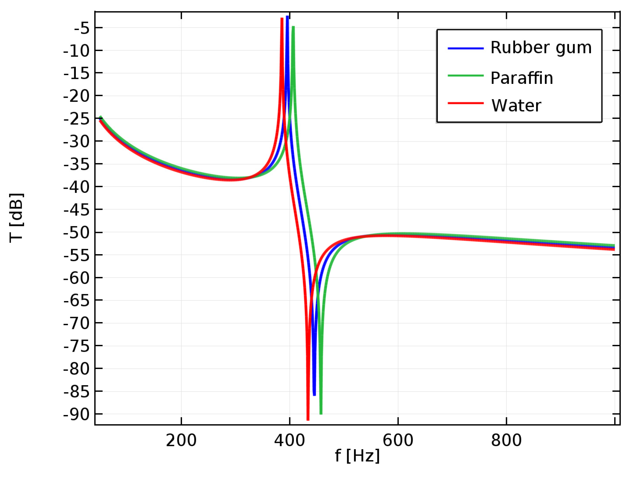
Starting from these results, the acoustical behavior of the same 3D configuration structure with a different matrix has been explored by considering air spheres in a rubber gum matrix or in a paraffin matrix. These materials were chosen for their environmentally sustainable features. Rubber gum is a versatile natural material, is cost-effective, is tear and abrasion resistant, has superior resilience and tensile and elongation characteristics, and is also a recyclable material. Natural paraffin has good acoustical and thermal properties and it has a very high heat capacity, meaning it is able to absorb and retain a great amount of heat. As it can be seen in
Figure 6 for the structure with
H = 10 cm, the result in terms of the transmission coefficient is rather promising in the sense that rubber and paraffin provide almost the same performances as a water matrix, but they represent a more realistic support for the proposed structure.
Figure 6.
Modulus of the transmission coefficient of an array of air spheres (H = 10 cm, a = 10 mm) embedded in different materials.
Figure 6.
Modulus of the transmission coefficient of an array of air spheres (H = 10 cm, a = 10 mm) embedded in different materials.
4. Conclusions
Low frequency sound insulation is a very critical issue, due to the fact that, with conventional materials, high surface mass is needed and, therefore, significantly massive, bulky and expensive solutions are required. Furthermore, since conventional materials are synthetic and therefore have a high embodied energy, the need to achieve noise reduction by means of environmentally sustainable solutions is becoming a more diffuse and felt problem.
In this paper, the design of an acoustic metasurface composed of air spheres or cylinders immersed in a water matrix for controlling sound transmission in airborne applications has been studied. A few simple structures have been numerically analyzed by means of full-wave simulations based on the finite-element method.
The results have shown that such metasurfaces can be effectively used to control the transmission coefficient of a structure and tailor the desired operation range by acting on the metasurface geometrical parameters, and, thus, on its equivalent impedance. The full-wave simulations results in terms of noise reduction are very promising. They demonstrate that, through the implementation of a properly designed structure, i.e., by acting on its thickness and on the radius and relative distances of the inclusions, it is possible to achieve, beyond the resonance peak and in the antiresonance region, a significant decrease of the transmission coefficient compared to the one obtainable with a homogeneous structure. The price paid for this is an increased transmission and a resonant behavior occurrence at extremely low frequencies. Therefore, there is a lower frequency limit for which the proposed metasurface proves to be more effective than a homogeneous structure. In the examples shown for cylindrical inclusions, such limit is in the range 250–300 Hz.
The advantages of using a metasurface such as the one proposed in this work are its small thickness and the fact that it can be based on a flexible host material (water, paraffin or rubber gum in our examples). This provides a significant advantage in terms of the number of possible applications on a wide range of substrates. The small thickness and weight of the structure also provide the possibility to extend the operation range by designing a metasurface as a superposition of different thin layers, with each one working in a different frequency band.
Another significant point of strength of the proposed approach is the possibility to build the metasurface with environmentally sustainable materials, such as paraffin or rubber gum. This is possible since the control of the transmission coefficient and of the operation frequency range mainly depends on the geometrical structuring of the metasurface, and to a lesser extent on the materials employed.
Future developments will include the realization of some prototypes that will be tested in an impedance tube in order to verify the actual transmission loss properties of the metasurfaces.


 ,
, 