Article

FEM Analysis of Fluid-Structure Interaction in Thermal Heavy Oil Recovery Operations

1
Department of Geotechnical Engineering, Tongji University, No.1239, SiPing Road, Shanghai 200092, China
2
Department of Architectural Engineering, North China Institute of Aerospace Engineering, No.133, AiMinDong Str., GuangYang District, LangFang 065000, China
*
Author to whom correspondence should be addressed.
Sustainability 2015, 7(4), 4035-4048; https://doi.org/10.3390/su7044035
Submission received: 28 December 2014 / Revised: 23 March 2015 / Accepted: 24 March 2015 / Published: 8 April 2015
(This article belongs to the Section Sustainable Engineering and Science)

Abstract

:
In the process of heavy oil thermal recovery, the creep of strata can often be accelerated due to injection pressure, the temperature of steam, the structural characteristics of rock itself and other factors. However, the effect of creep in strata may cause various types of damage in underground mining, such as fracture or deformation of oil casings, and so on. The mechanism of fluid–structure interaction provides a powerful theoretical guidance for stratum creep, which happens during the process of heavy oil thermal recovery. According to existing research, a practical engineering finite element model of Jin.25 Block in Liaohe Oilfield was built based on the finite element analysis software ADINA, and the numerical simulation of the thermal recovery stratum creep of Jin.25 Block was done using the fluid–structure interaction (FSI) calculation module. The results were compared and analyzed, combining each influencing factor of the stratum creep in practical engineering. It is proposed that steam injection pressure should not exceed 14 MPa while enhancing oil recovery by increasing the injection pressure; the main reason is that temperature impact on casings is closely related to the change in stratum creep stress. However, particular attention should be paid to the thermal sensitivity of casing itself and creep deformation when the hydraulic conductivity magnitude is above 1 × 10⁻⁹ m/s, so as to effectively prevent or minimize the economic loss caused by stratum creep.

1. Introduction

Creep effect [1,2,3,4] of strata is one of the important factors causing damage to oil casings in oilfields; especially during the process of heavy oil thermal recovery, the creep effect is more obvious. Stratum creep is the changing characteristics of stratum strain from the original condition of field stress over time. Therefore, wells without casings generate radial shrink. After well completion, additional loads on the casings increase when resisting shrink. Given a sufficiently long period, this additional load tends to stabilize; the stable pressure is called the “creep load of casing”. Therefore, the damage rate of casings is quite large. According to a survey from 1976 thermal recovery oil wells in Jinzhou Oil Production Plant in the year of 2002, the number of damaged casing wells was 524, which accounted for 26.5% of the total number of wells. This phenomenon is a serious threat to the normal exploitation of oilfields.
During the process of steam injection and thermal recovery, stratum creep is one of the most important reasons for casing damage in oil reservoirs [5,6,7]. The occurrence of stratum creep is intimately related to the mechanism of fluid–structure interaction. Xu and Xu [8] proposed that the stability of the creep process in boreholes is a mechanics problem, including rock properties, stress state, and stability under fluid–structure interaction. Liu and Liu et al. [9] built the nonlinear deformation coupled theory model of fluid seepage and rock medium in reservoirs and established the relationship between oilfield injection production and crustal stress field disturbance and stratum deformation. Liu and Yu [10] established a new mathematical model to simulate stress distribution from the combination of casing-cement and the surrounding rock ring, considering seepage and stress interaction during the oil development process based on fluid–solid coupling theory.
Additionally, Collins [11] put forward that geomechnics can enhance the SAGD (Steam Assisted Gravity Drainage) process and subsurface reservoir deformation could result in surface heaves, which can provide the location of subsurface deformations.
Li et al. [12] built a numerical scheme, and studied the permeability change of a simulated granular material like sandstones with the deformation and damage development of the solid part based on the commercial code PFC (Particle Flow Code).
Based on a new version of the Reis drainage model, Azad and Chalaturnyk [13] proposed a coupled mathematical model and revealed the effect of geomechanics in the process and how it could successfully decrease the modeling time. Rutqvist et al. [14] analyzed coupled multiphase fluid flow, heat transfer, and deformation in fractured porous rock base on TOUGH2 and FLAC3D which were linked and jointly executed for coupled (THM) analysis.
Tran et al. [15] pointed out that the accuracy and the large run time of the coupled solid-mechanics fluid-flow model limited the application of coupled model in full-field studies, and then presented a new iterative coupling method to solve the coupling problem between Reservoir Simulator and Geomechanics Module.
Dusseault [16] put forward that sand production from high porosity sandstones is an example of quasi-static solid–liquid coupling, and this new understanding of dynamic-static coupling has opened up a new applications area in geomechanics.
Cai et al. [17] used the Lattice Boltzmann Method to simulate fluid–solid coupling heat transfer in fractal porous medium, which indicated that Lattice Boltzmann Method is feasible and reliable in revealing the phenomenon and rules of fluid–solid coupling heat transfer in complex porous structures.
Therefore, correctly using the fluid–structure interaction mechanism is the key to analyzing the reasons for creep effect in the process of steam injection thermal recovery.

2. Fluid-Structure Interaction of Steam and Rock

Stratum fluid-structure interaction seepage flow [18,19,20] mainly refers to the coupling between rock mass structure and pore fluid (gas or liquid) [21]. For instance, in mining engineering [22], stratum subsidence may occur due to the dewatering from underground; water bursting in mines and the urban land subsidence caused by groundwater pumping; stratum creep caused by water or steam injection exploitation in oil wells; coal mining between water-contained strata and artesian aquifers; and the effect of slope stability on dam structure due to seepage, and so on. All of the above are related to fluid–structure interaction [23].
During the process of steam injection thermal recovery, the coupling effect of steam and rock is specifically manifested in the following aspects:
(1)
When injected into the reservoir, the steam exceeds the overburden load and is subjected to the horizontal stress effect. If the steam pressure increases in the exploitation process, the oil-bearing reservoir would generate extruding deformation because of the effect of stress, and then the pore space would get smaller, thereby causing the crude oil to flow out from the reservoir. In fact, the pressures that the crude oil burdens in all directions are equal to each other. The reservoir pressures in the vertical and the horizontal directions would decrease at the same level if the steam injection was stopped; therefore, thermal recovery by steam injection would cause compression deformation in the horizontal direction. Thus, reservoir deformation may also influence and affect the oil movement underground.
(2)
Because of the compression in the oil reservoir, the porosity may be reduced and then the hydraulic conductivity would decline, the flow resistance would increase and the current velocity would decrease. However, the decrease of current velocity inhibits the flow rate of steam pressure, which in turn prevents the further compression of pore or fracture.
(3)
Steam has an impact on the stress–strain constitutive relationship of rock mass [24].
(4)
Fluid seepage flow equations [25].
Seepage flow equations include the continuity equation and the constitutive equation of seepage, and the deformation field equations of rock include the equilibrium equation, the geometric equation and the constitutive equation.
The relationship between the deformation of rock skeleton and seepage coupling effect may be expressed as:
K = A   e x p ( B σ ´ z )
The relationship between rock peak strength and fluid pressure may be shown as:
σ c = a 1   e x p ( b 1 p )
where
  • K is the hydraulic conductivity in md,
  • σ ´ z is the vertical effective stress for rock mass in md,
  • p is the fluid pressure, and
  • A, B, a1, b1 is the rock material constant greater than zero, respectively.

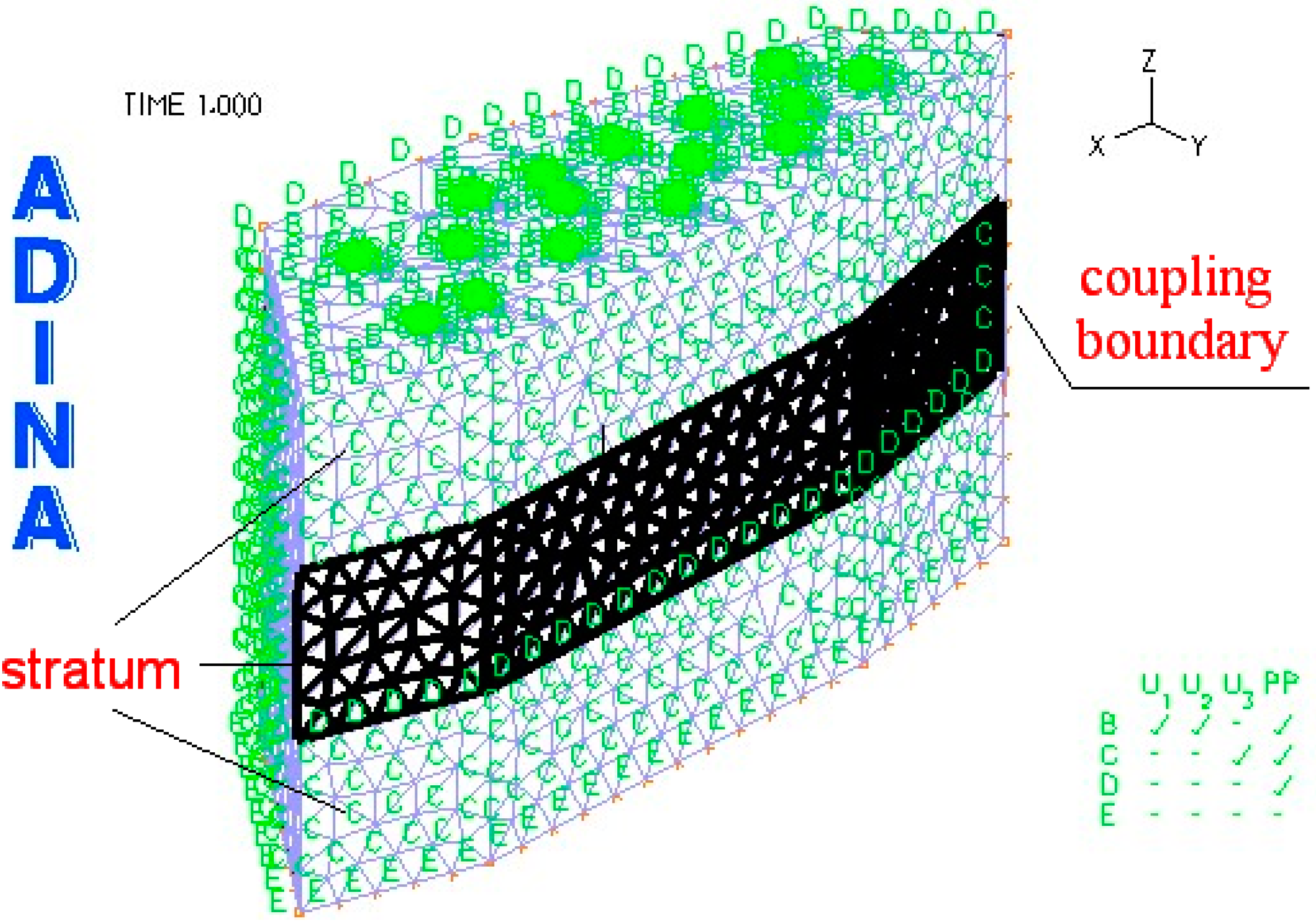
3. Model Building and Solution

Taking Jin.25 Block in Liaohe Oilfield as an example, the structural model and the fluid model of creep strata in this block during the process of thermal recovery by steam injection were built based on the finite element software ADINA, and then the coupling was calculated in the FSI module in ADINA. The results were extensively analyzed.

3.1. Model Building

The geometric model close to the actual project was built according to Jin.25 Block and the well points were arranged based on its actual intensity, which includes four high pressure steam injection wells; the others are oil-producing wells. The structural model and the fluid model were respectively established, while the strata as the structure model are the investigated subjects, which are composed of the rock mass with various types of lithology.
The fluid–structure coupling model was based on the assumptions as follows:
(1)
The coupled system consists of solid and fluid;
(2)
Interstitial fluid is completely filled within the rock and obeys the Darcy’s law;
(3)
The parameters of the reservoir do not affect each other and stay constant;
(4)
Transient analysis and large displacement assumptions were set in the coupled model;
(5)
The constitutive relationship of materials was based on previous test results and the constitutive relationships of material tests.
The two models were built by the way of “Parasolid” in ADINA. The structure model and the fluid model is shown in Figure 1 and Figure 2, respectively. The material parameters are listed in Table 1.
Figure 1. Calculation model of structure.
Sustainability 07 04035 g001
Figure 2. Calculation model of fluid.
Sustainability 07 04035 g002
Table 1. The relevant material parameters of model.
Material TypeDensity (kg/m3)Viscosity (Pa·s)Thermal Conductivity (J/m·s·°C)Thermal Capacity (J/m3·°C)Modulus of Elasticity (MPa)Poisson RatioThermal Dilation Coefficient
Stratum 125700.00025.580040000.182.5 × 10−5
Stratum 228000.00036.0100050000.22 × 10−5
Stratum 329400.00027.590022,0000.31.9 × 10−5
Steam (250 °C, 12 MPa)8080.000116.04200//3 × 10−5
Steam (320 °C, 10 MPa)520.0000026.04200//3 × 10−5
Steam (320 °C, 15 MPa)6790.0000856.04200//3 × 10−5
Steam (320 °C, 12 MPa)6700.000056.04200//3 × 10−5
Water10000.0016.04200//3 × 10−5

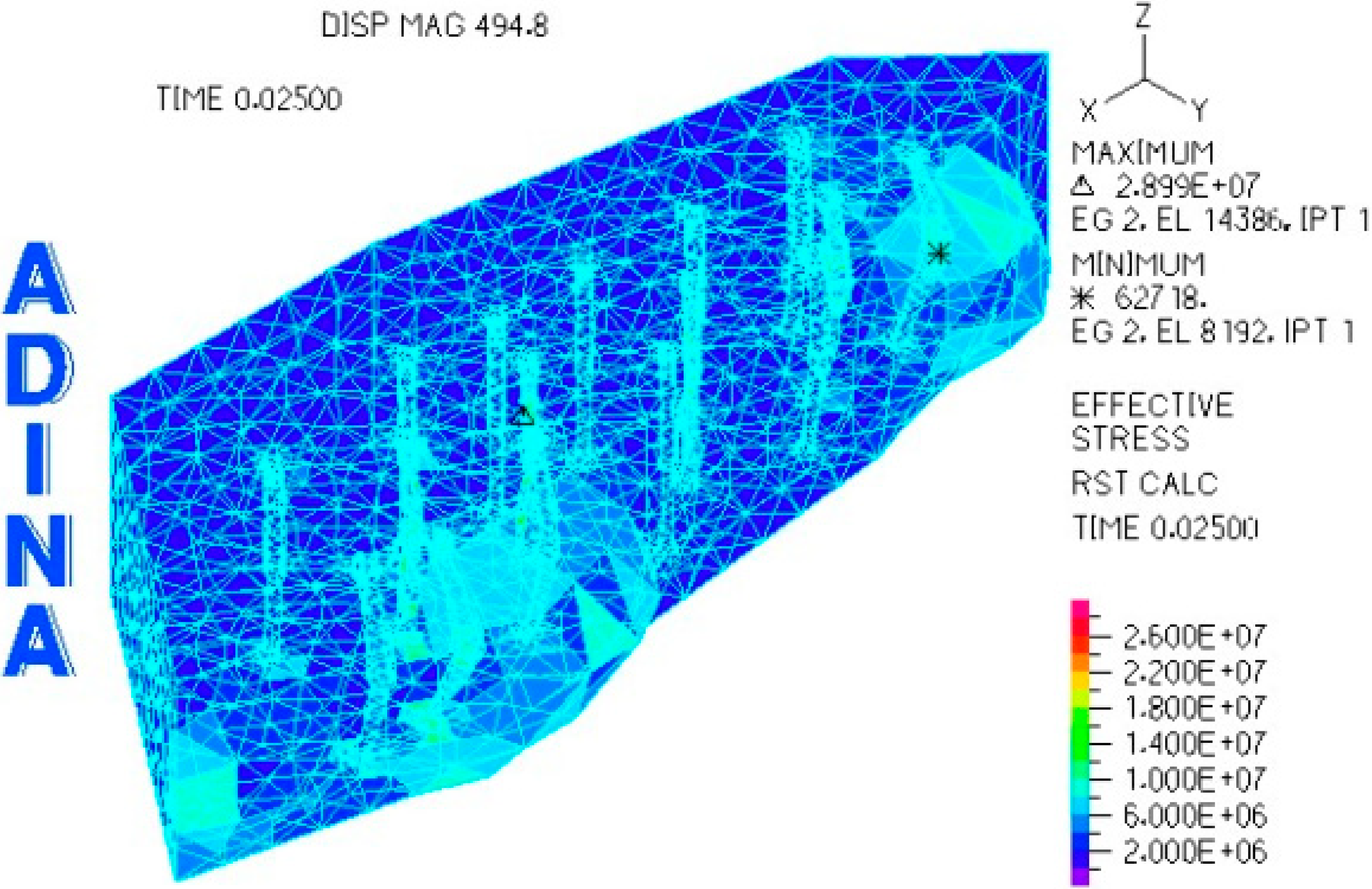
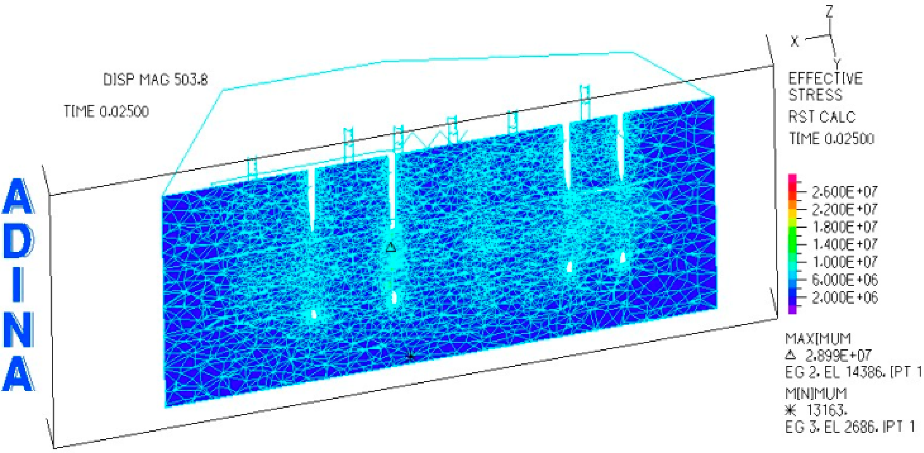
3.2. Coupling Results

Jin Oil Field has been exploited since 1979 and the exploitation in heavy oil blocks has occurred more recently. Accordingly, damage to casing wells occurs frequently. According to the survey results of 1976 oil wells in Jinzhou Oil Production Plant in 2002, the number of heavy oil wells accounted for 30.8% in all of the oil damaged casing wells, wherein, the fracture casing wells accounted for 10% of the damaged casing wells, and 62.8% of which occurred in the reservoir site. Therefore, it is our focus to analyze the damaged casing wells in the reservoir site.
According to the numerical analysis model, the solution for the fluid–structure interaction was obtained, which shows that the most serious creep stratum occurred in the reservoir site during the process of the thermal recovery fluid–structure interaction. As is shown in Figure 3, the creep deformation was most obvious in the reservoir section, which is almost consistent with the survey results of the actual project.
Figure 3. Reservoir structure deformation.
Sustainability 07 04035 g003
In terms of effective stress, the larger the effective stress around the wellbores is, the more seriously damaged the casings will be. As is shown in Figure 4, the section in Plane XZ which includes three steam injection wells and a production well suggests that most steam injection well sites of Jin.25 Block are included. It can be also clearly seen that it is in the middle section that the creep deformation occurred. What is the more important point is that the concentration of the maximum effective stress is in the middle section where the second well is located, which is counted from left (As “△” is shown in Figure 4). According to the actual survey results from Jin.25 Block, it shows that the majority of the damaged casing wells were concentrated in this area, as is shown in Figure 5. Consequently, it has shown a good agreement with the results of the numerical simulation.
Figure 4. XZ-plane section.
Sustainability 07 04035 g004
Figure 5. Distribution of damaged casing wells in Jin.25 Block.
Sustainability 07 04035 g005

4. Analysis and Discussion of Results

In petroleum engineering, thermal recovery has become the main method of heavy oil exploitation. However, in China, heavy oil accounts for more than 30% of its total oil resources, recurrent flooding alternating disturbance is typical of thermal recovery in reservoirs and the temperature always changes drastically, so the thermal recovery process in heavy oil reservoirs relies on a typical heat–fluid–structure interaction system [26,27]. With the continuous advance of injection time, the stress state of deep underground rock becomes complex and changeable; finally, leading to the formation of creep effect, and the creep effect is particularly obvious in the reservoir section. There are many factors that influence stratum creep, which can restrict as well as interact with each other. In this paper, three main factors were chosen: steam injection pressure, steam injection temperature and hydraulic conductivity, respectively. The stratum creep displacement, the effective stress and the strain were calculated considering the effect of fluid–structure interaction on the factors above. Then, the results were analyzed and finally some project proposals were put forward to protect oil casings.

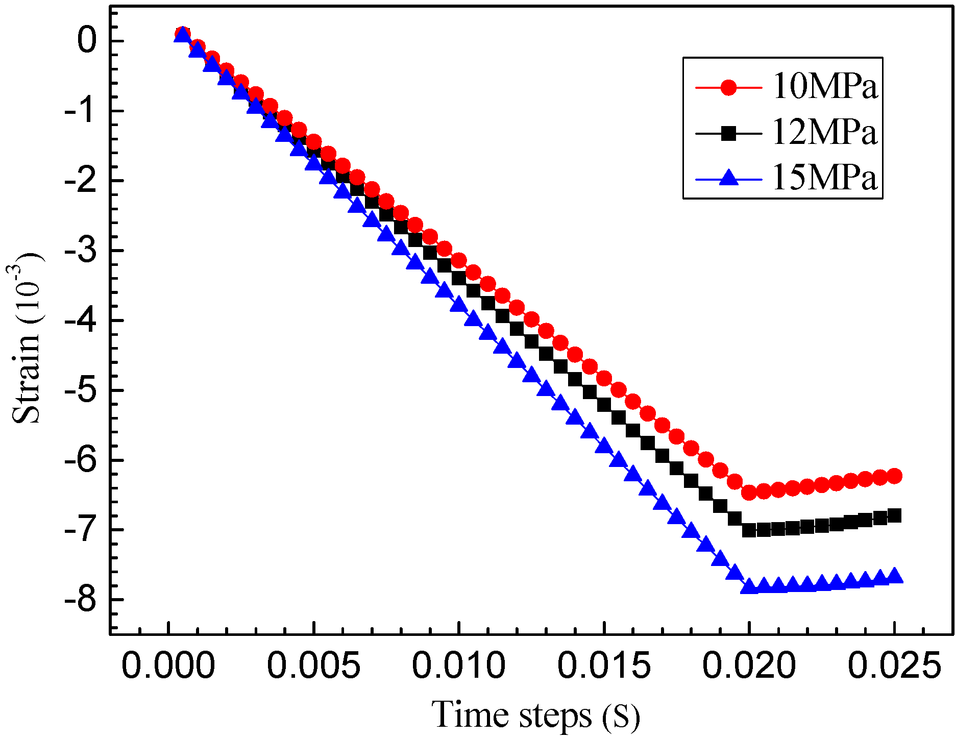
4.1. Influence of Steam Pressure on Coupled Creep

Steam injection pressure is generally high in the process of thermal recovery by steam injection. On the one hand, high pressure steam can accelerate the softening of ion in heavy oil; on the other hand, it also provides an effective power source for oil production. However, it inevitably promotes the fluid-structure interaction effects in high pressure injection production at the same time, which could result in the fast creep of strata and the acceleration of casing damage. Therefore, the steam injection pressure is a factor that we need to consider.
Combined with the actual situation of steam injection in Jin.25 Block, three different steam injection pressures (10 MPa, 12 MPa and 15 MPa, respectively) were mainly considered in this simulation. The changes that occurred when the steam injection pressure was changed in the maximum creep displacement, the effective stress and the strain are shown in Figure 6, Figure 7 and Figure 8.
Along with the advance of the steam injection, the maximum creep displacement, effective stress and the absolute value of the strain increased constantly, whereby some negative effects may occur such as lateral extrusion, expansion creep in all directions and stress concentration around the casing wellbores, which may lead to deformation and even destruction of casings.
Figure 6. Creep displacement of reservoir at different steam pressures.
Sustainability 07 04035 g006
Figure 7. Effective stress around wells at different steam pressures.
Sustainability 07 04035 g007
Figure 8. Strain around wells at different steam pressures.
Sustainability 07 04035 g008
In the longitudinal comparative analysis, when the steam injection pressure increased from 10 MPa–15 MPa, it can be seen that the parameters of creep effect were obviously increased with the increase of injection pressure from the creep displacement, and stress and strain time history curves, which may more easily affect the normal use of the casings in injection wells. Therefore, reasonable injection pressure is an important measure in the injection process.

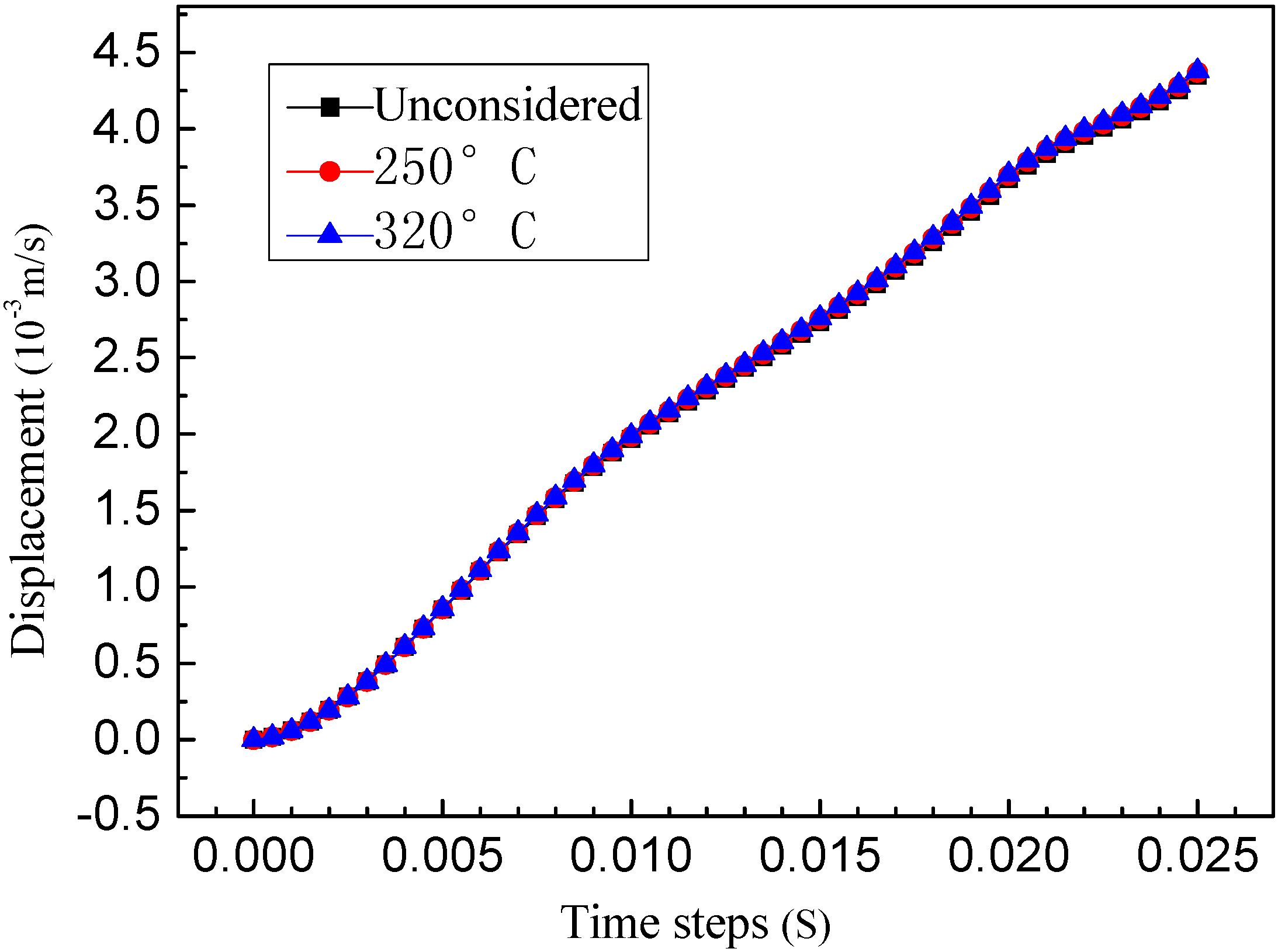
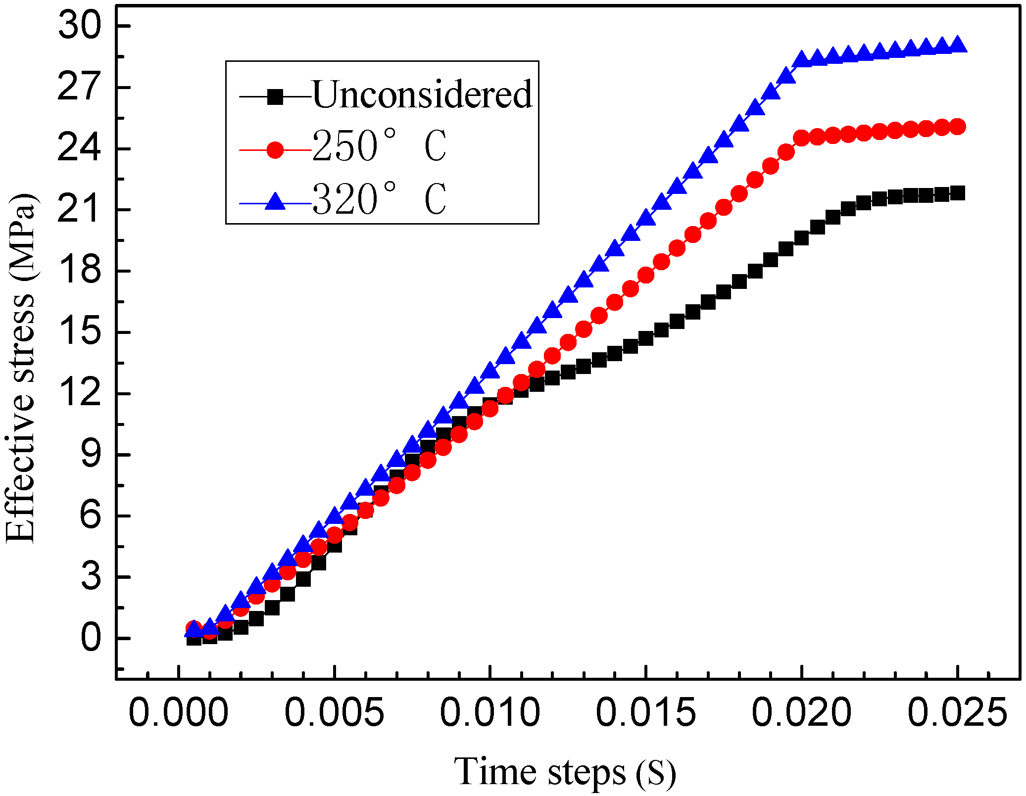
4.2. Influence of Steam Injection Temperature Stress on Coupled Creep

The viscosity of heavy oil is high, generally more than 50,000 MPas. Therefore, it is very important to reasonably maintain a certain high temperature steam for heavy yield of oil. The heating mechanism of heavy oil exploitation can be summarized as follows:
(1)
Energy transfer is due to the movement of fluid injection.
(2)
Heat conduction is induced from the high temperature region to the low temperature one in the reservoir.
(3)
Heat convection between the original fluid and the injection fluid is due to the heterogeneity of the reservoir.
According to the actual case of steam injection in Jin.25 Block, three cases were considered including 250 °C, 350 °C and without considering temperature, the maximum creep displacement, the effective stress and the strain time history curves, which are shown in Figure 9, Figure 10 and Figure 11.
The time history curve of the maximum creep displacement shown in Figure 9 indicates that the injection temperature hardly affects the creep displacement in the injection process, but it can greatly affect the stress and the strain of creep stratum as is shown in Figure 10 and Figure 11. Especially if temperature is not considered, the change in the effective stress is unstable and the strain is much smaller when taking temperature into consideration. Therefore, injection temperature also plays an important coupling role in creep strata and should not be neglected.
Figure 9. Creep displacement of reservoir at different temperatures.
Sustainability 07 04035 g009
Figure 10. Effective stress around wells at different temperatures.
Sustainability 07 04035 g010
Figure 11. Strain around wells at different temperatures.
Sustainability 07 04035 g011

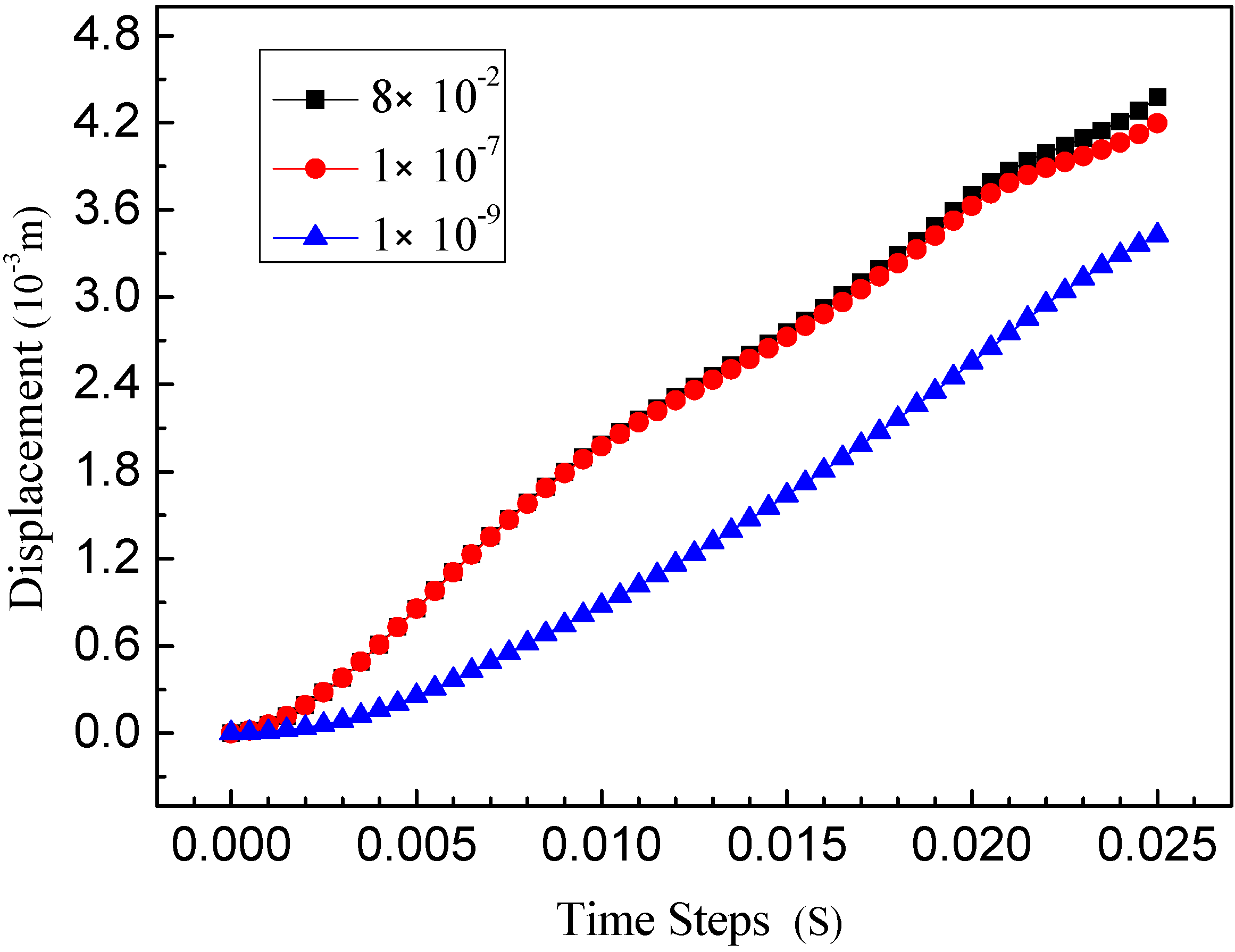
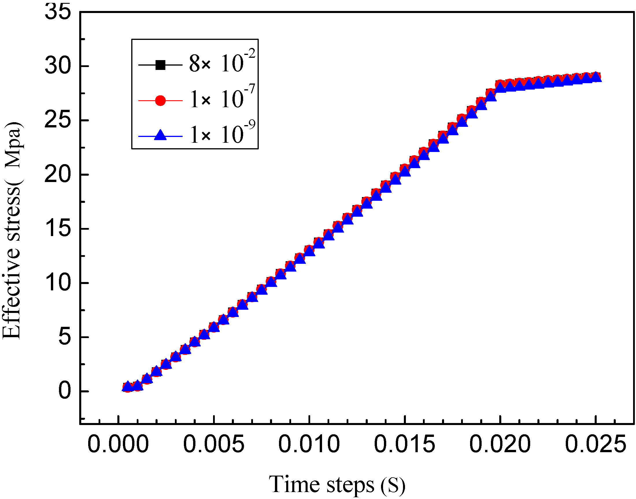
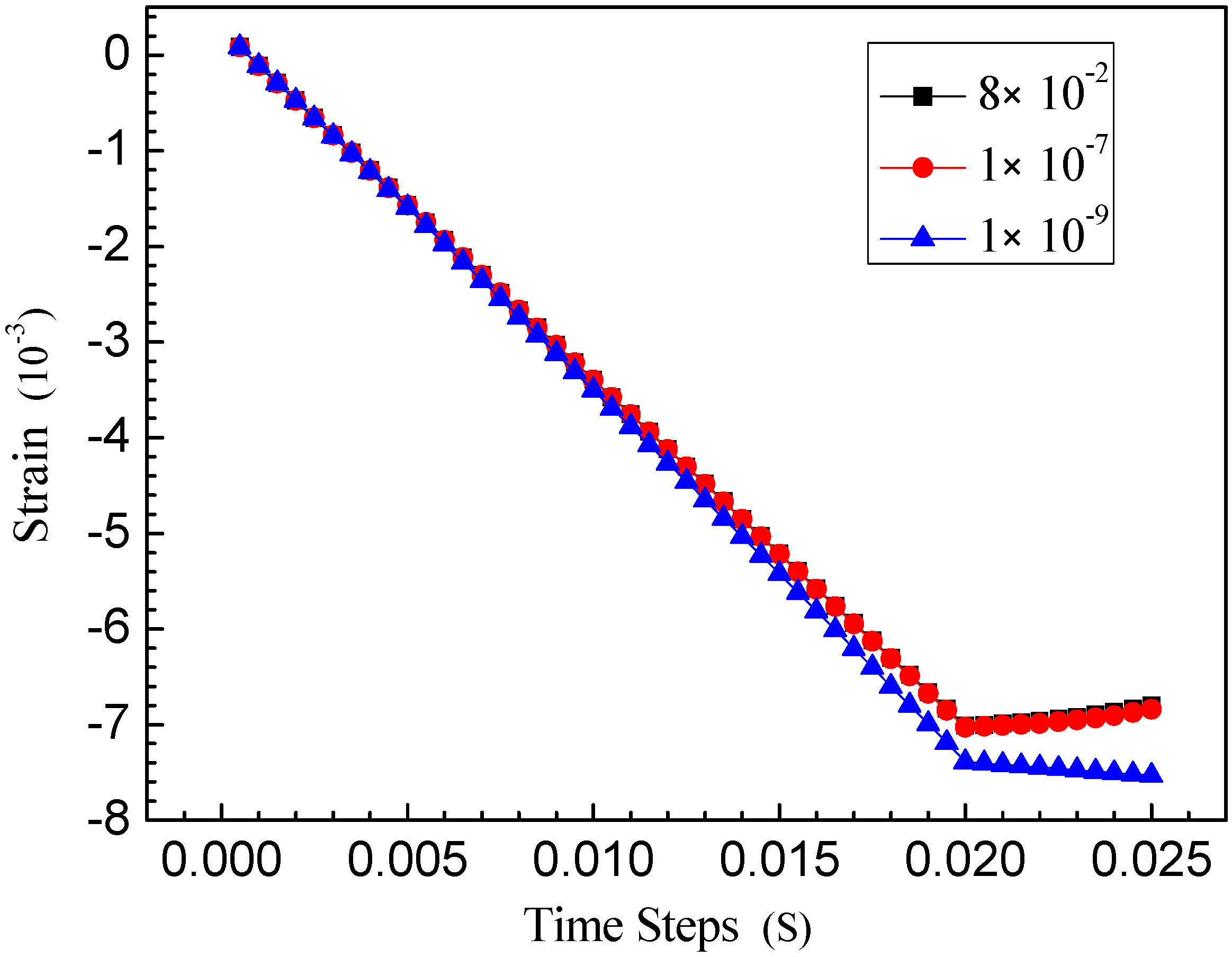
4.3. Influence of Hydraulic Conductivity on Coupled Creep

In Darcy’s law, the proportional coefficient K is called hydraulic conductivity or permeability coefficient. In isotropic media, hydraulic conductivity is defined as the flow unit ratio of hydraulic gradient. Hydraulic conductivity represents a physical quantity (dimension L/T) with the ability to transport fluid in porous media. So, it is related to the nature of fluid and the skeleton.
Correct determination of hydraulic conductivity is crucial in related seepage numerical analysis. The hydraulic conductivity value mainly depends on the shape, the size and the connectivity of pores. Three strata in different hydraulic conductivities were considered in this model, which were 8 × 10⁻² m/s, 1 × 10⁻⁷ m/s and 1 × 10⁻⁹ m/s, respectively. The maximum displacement, the effective stress and the strain of the formation creep in different hydraulic conductivities are respectively shown in Figure 12, Figure 13 and Figure 14.
Figure 12. Displacement of reservoir at different hydraulic conductivities.
Sustainability 07 04035 g012
As can be seen from Figure 12, in the same injection condition, the differences of the maximum creep displacement were not large when the hydraulic conductivity decreased from 8 × 10⁻² m/s to 1 × 10⁻⁷ m/s, but the differences were significant when the hydraulic conductivity was 1 × 10⁻⁹ m/s; namely, that the creep displacement value decreased more than did the former two, which indicates that the hydraulic conductivity of the creep displacement is not a simple linear change and it is closely related with the magnitude of the hydraulic conductivity. So, it can be generally inferred that 1 × 10⁻⁹ is a watershed for the creep displacement. The strain time–history curve can roughly reflect this change as is shown in Figure 14, while Figure 13 shows that the difference in hydraulic conductivity of effective stress is little.
Figure 13. Effective stress around wells at different hydraulic conductivities.
Sustainability 07 04035 g013
Figure 14. Strain around wells at different hydraulic conductivities.
Sustainability 07 04035 g014
To sum up, permeability has a certain effect on thermal creep displacement and strain, which mainly depends on the magnitude of hydraulic conductivity.

5. Conclusions

The three-dimensional multi-layer finite element model was established by the finite element analysis software ADINA, which described the fluid–structure interaction numerical simulation of stratum creep of Jin.25 Block in Jinzhou Oil Production Plant, Liaohe Oilfield. Three factors including injection pressure, injection temperature and hydraulic conductivity of rock were considered in determining their influence on stratum creep in the process of steam injection thermal recovery. The following conclusions can be drawn through the analysis of the time–history curves of creep displacement, effective stress and strain with several factors:
(1)
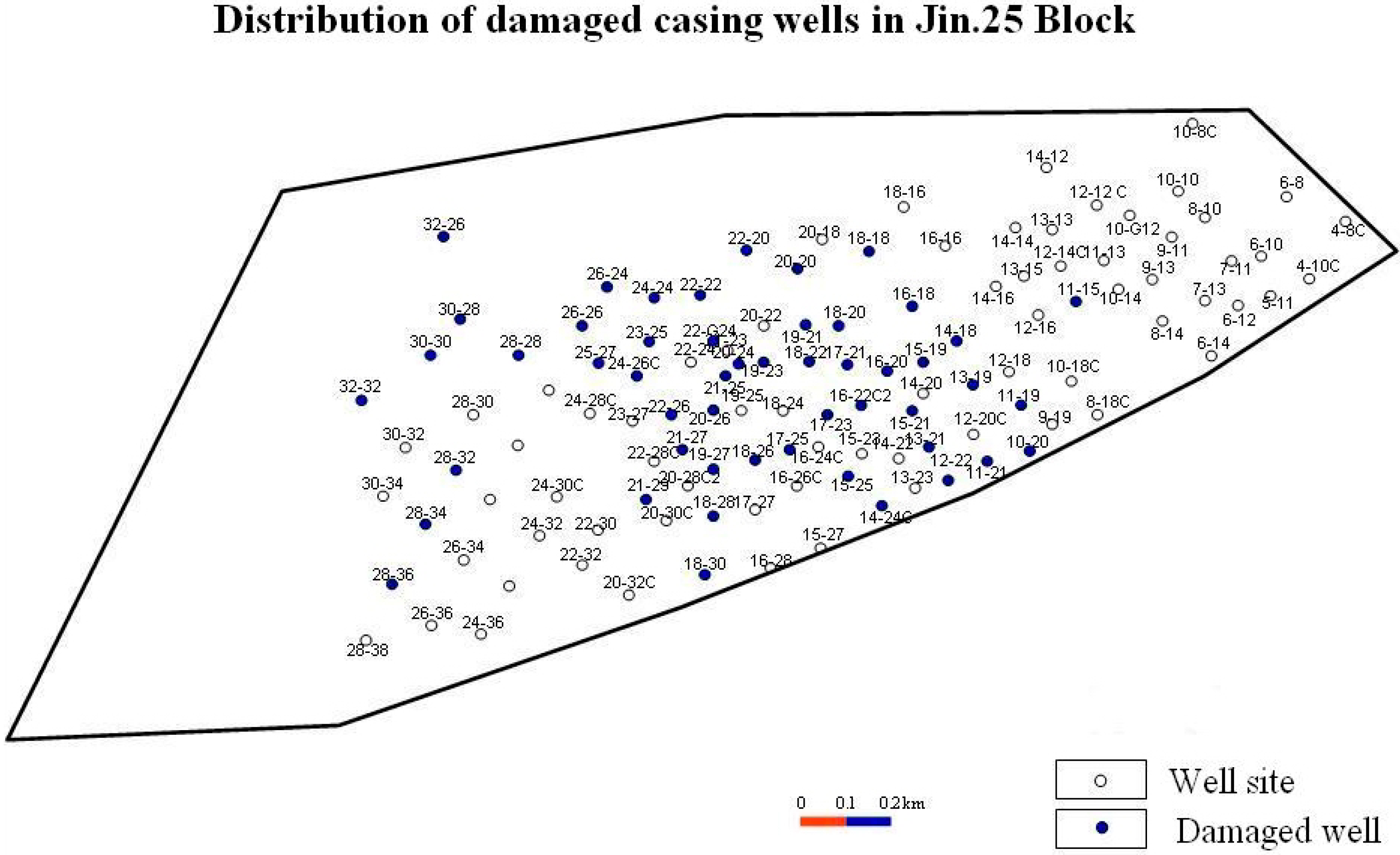
Steam injection at different pressures significantly impact stratum creep. In this model, according to the actual injection case in Jin.25 Block, coupling results analyses at different steam injection pressures are as follows: the formation creep displacement, the effective stress and the strain increased significantly with the incremental increases in steam injection pressure. Therefore, it is important to reasonably control the steam injection pressure while enhancing oil recovery, and when increasing the injection pressure, it is proposed that the steam injection pressure should not be more than 14 MPa.
(2)
Engineering practice has indicated that injection temperature could affect casing damage, but there are not enough data to prove whether the damage is related directly to the formation of creep or not. Nevertheless, the analysis results show that the influence of temperature on stratum creep displacement is very small while it has a large influence on effective stress and strain. Then, it can be inferred that the main reason for temperature impacting casings is closely related with the change in stratum creep stress, disregarding the thermal sensitivity of casing itself. Therefore, it is impractical to not consider the coupling effect of temperature in thermal recovery.
(3)
Hydraulic conductivities in different rocks are not the same; the impact on stratum creep mainly relies on the magnitude range of hydraulic conductivity. In general, creep deformation should be paid particular attention to when the hydraulic conductivity magnitude is above 1 × 10⁻⁹ m/s. In injection process, injection pressure or injection temperature can be significantly reduced to avoid the excessive stratum creep.

Acknowledgments

Financial support from the Planned Projects of Science and Technology Department of Hebei Province (NO. 09277130D), the Natural Science Fund Project of Hebei Province (NO. D2010000922) is gratefully acknowledged.

Author Contributions

Yao Yin developed the original idea and contributed to the research design. Liliang Liu was responsible for data collection and processing. Both authors have read and approved the final manuscript.

Conflicts of Interest

The authors declare no conflict of interest.

References

  1. Liu, H.X.; Zhang, P.; Gai, F. Study on Creep RULE of Salt Rock in Sichuan Region. Chin. J. Rock Mech. Eng. 2002, 21, 1290–1294. [Google Scholar]
  2. Savage, W.Z.; Braddock, W.A. A model for hydrostatic consolidation of Pierre shale. Int. J. Rock Mech. Min. Sci. Geomech. Abstr. 1991, 28, 345–354. [Google Scholar] [CrossRef]
  3. Yin, S.; Towler, B.F.; Dusseault, M.B. Numerical experiments on oil sands shear dilation and permeability enhancement in a multiphase thermoporoelastoplasticity framework. J. Pet. Sci. Eng. 2009, 69, 219–226. [Google Scholar] [CrossRef]
  4. Shafiei, A.; Dusseault, M.B. Geomechanics of thermal viscous oil production in sandstones. J. Pet. Sci. Eng. 2013, 103, 121–139. [Google Scholar] [CrossRef]
  5. Li, Z.F.; Zhang, Y.G.; Yang, X.J. Mechanics model for interaction between creep formation and oil well casing. Acta Pet. Sin. 2009, 30, 129–131. [Google Scholar]
  6. Wang, L.J. Study on Casing Loads in Creep Stratum. Master’s Thesis, China University of Petroleum, Beijing, China, 2007. [Google Scholar]
  7. Yang, H.L.; Chen, M.; Jin, Y.; Zhang, G.Q. Analysis of casing equivalent collapse resistance in creep formations. J. China Univ. Pet. 2006, 30, 94–97. [Google Scholar]
  8. Xu, Z.H.; Xu, X.H. The Fluid-Sold Coupled Flowing through Porous Media in Mining Engineering. China Mining Mag. 1996, 5, 53–60. [Google Scholar]
  9. Liu, J.J.; Liu, X.G.; Hu, Y.R.; Zhang, S.Z. Study of Fluid-Solid Coupling Flow in Low Permeable Oil Reservoir. Chin. J. Rock Mech. Eng. 2002, 21, 46–51. [Google Scholar]
  10. Liu, J.J.; Yu, X.B. Stress analysis on the combination of casing-cement ring-surrounding rock considering fluid-solid coupling. Electr. J. Geotech. Eng. 2012, 17, 1863–1873. [Google Scholar]
  11. Collins, P.M. Geomechanical effects on the SAGD process. SPE Reservoir Eval. Eng. 2007, 10, 367–375. [Google Scholar] [CrossRef]
  12. Li, L.; Holt, R.M. Simulation of flow in sandstone with fluid coupled particle model. In Proceedings of DC Rocks 2001, the 38th US Symposium on Rock Mechanics (USRMS), Washington, DC, USA, 7–10 July 2001.
  13. Azad, A.; Chalaturnyk, R.J. Geomechanical Coupling Simulation in SAGD Process; A Linear Geometry Mode; University of Alberta: Edmonton, AB, Canada, 2009; pp. 9–14. [Google Scholar]
  14. Rutqvist, J.; Wu, Y.S.; Tsang, C.F.; Bodvarsson, G. A modeling approach for analysis of coupled multiphase fluid flow, heat transfer, and deformation in fractured porous rock. Int. J. Rock Mech. Mining Sci. 2002, 39, 429–442. [Google Scholar] [CrossRef]
  15. Tran, D.; Settari, A.; Nghiem, L. New iterative coupling between a reservoir simulator and a geomechanics module. SPE J. 2004, 9, 362–369. [Google Scholar] [CrossRef]
  16. Dusseault, M.B. Coupled processes and petroleum geomechanics. Elsevier Geo-Eng. Book Series 2004, 2, 49–62. [Google Scholar]
  17. Cai, J.; Huai, X. Study on fluid–solid coupling heat transfer in fractal porous medium by lattice Boltzmann method. Appl. Therm. Eng. 2010, 30, 715–723. [Google Scholar] [CrossRef]
  18. Zhou, Z.J. Theory and Application Research of Fluid-Solid Coupling Seepage in Low Permeability Reservoir; Daqing Petroleum Institute: Daqing, China, 2003. [Google Scholar]
  19. Li, S.C.; Chen, Z.Q.; Miao, X.X. Bifurcation of fluid-solid coupling flow in broken rock. J. China Coal 2008, 33, 754–759. [Google Scholar]
  20. Hamid, R.G.; Lewis, R.W. A Finite element double porosity model for heterogeneous deformable porous media. Int. J. Numer. Anal. Meth. Geomech. 1996, 20, 831–844. [Google Scholar] [CrossRef]
  21. Masoud, B.; Abdolrahman, D.; Iraj, M. Simulation of Fluid-Structure and Fluid-Mediated Structure-Structure Interactions in Stokes Regime Using Immersed Boundary Method. Sci. World J. 2014, 2014. Article 782534. [Google Scholar]
  22. Nan, S.Q.; Ge, Y.; Gao, Q. Fluid solid coupling numerical simulation and parameter optimization of surrounding strata filling mining. Metal Mine 2011, 6, 20–24. [Google Scholar]
  23. Zhao, Y.S. Multi Field Coupling of Porous Medium Effect and Engineering Response; Science Press: Beijing, China, 2010. [Google Scholar]
  24. Fan, Z.H.; Zhang, C.S.; Xiao, H.B. Simulation analysis of deformation for unsaturated expansive soils based on fluid-solid coupling characteristics. J. Cent. South Univ. (Sci. Technol.) 2011, 42, 758–764. [Google Scholar]
  25. Liang, B.; Sun, K.; Xue, Q. Research of Fluid-solid Coupling in Ground Engineering. J. Liaoning Tech. Univ. 2001, 2, 129–134. [Google Scholar]
  26. Su, Y.L.; Xu, Y.T. Application of Fluid-solid Coupling Theory in Oil Production Engineering. Inner Mongolia Petrochem. 2009, 10, 17–18. [Google Scholar]
  27. Liu, J.J.; Feng, X.T. Advance of studies on thermo-hydro-mechanical interaction in oil reservoir in China. Rock Soil Mech. 2003, 24, 646–651. [Google Scholar]

