The ancient monastery, connected to the church of SS. Michele e Gaetano in fashionable Via Tornabuoni opposite the well-known Palazzo Antinori, is one of the most important examples of Baroque architecture in Florence. Its cloister converted into the present showroom is the case study.
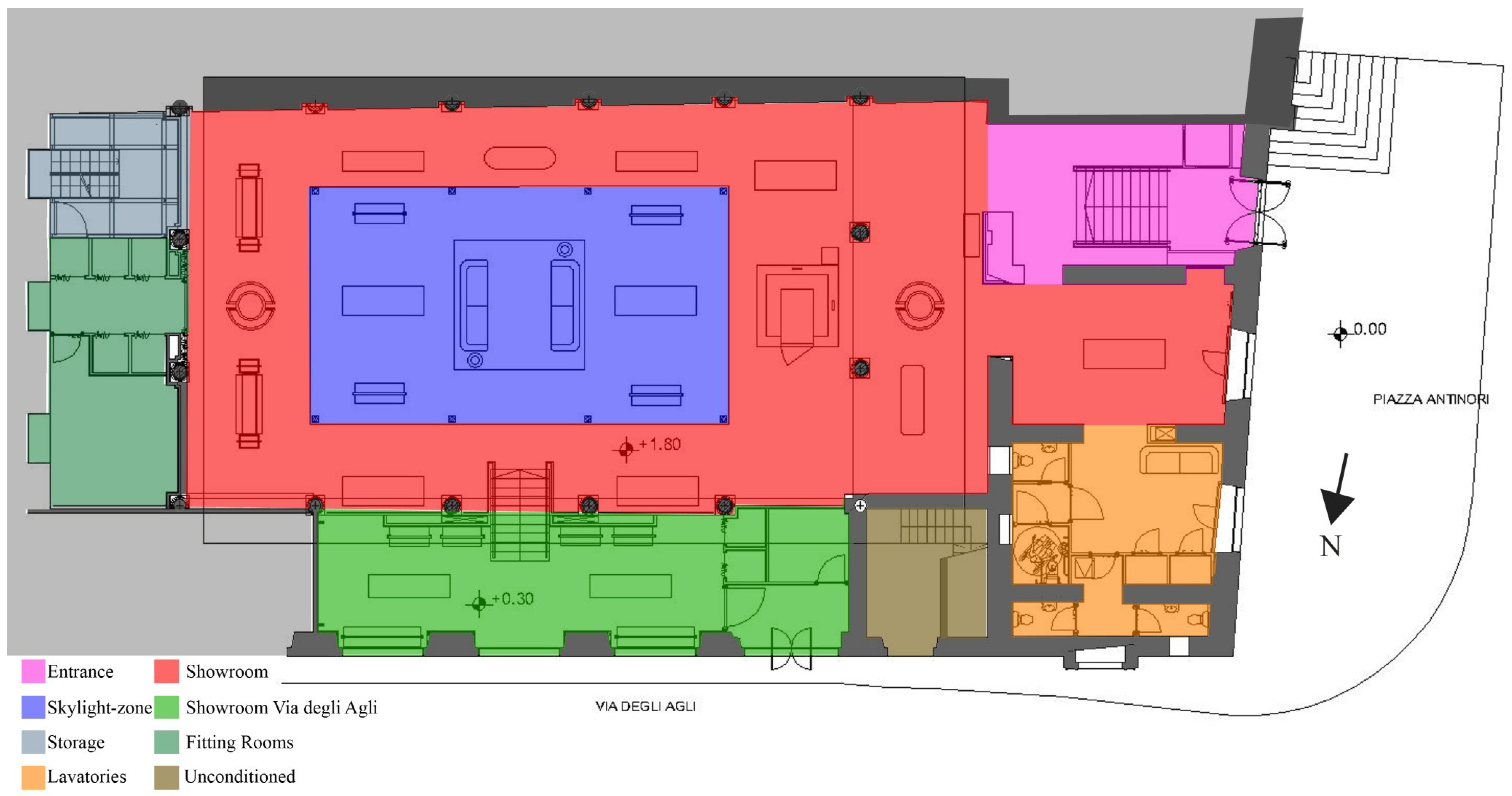
Figure 1.
Scheme of cloister system and thermal zones.
2.1. Existing Situation Analysis
The hourly values of the thermal internal conditions for commercial stores, sensible and latent heat gains due to people occupation and equipment, as suggested in [
14], ventilation and fresh air flow rate [
15,
16], were used for the hourly calculations and given in
Table 4. These internal gains were considered during opening times, six days a week from 8:00 to 20:00. The system plant was evaluated in working conditions from 7:00 to 20:00, to consider the presence of the cleaners and preparation of the store before opening. ASHRAE [
17] and European standards [
18] respectively suggest, for showroom areas, thermal gain values and illuminance values, due to the artificial lighting system. In particular, the ASHRAE standards provide a constant value of the sensible heat gain of 18 W/m
2. The European standards also provide a minimum limit of indoor illuminance value of 500 lux in exhibition areas and 200 lux in walking areas.
Table 4.
ASHRAE conditions [
14].
Table 4.
ASHRAE conditions [14].
| Thermal zones | Entry | Showroom | Skylight | Storage | Lavatories | Fitting room | Closing time |
|---|
| ASHRAE classification | Retail, sales | Storage | Lavatories | Dressing/Locker room | Unconditioned |
| Infiltration [Vol/h] | 0.5 | 0.5 | 0.5 | 0.5 | 0.5 |
| Fresh air rate [Vol/h] | 2 | 0.5 | 2 | 2 | 0 |
| Lighting gains [W/m2] | function | hourly | hourly | Hourly | 0 |
| Occupancy sensible gain | hourly | hourly | hourly | Hourly | 0 |
| Occupancy latent gain [W/m2] | hourly | hourly | hourly | Hourly | 0 |
| Equipment sensible gain [W/m2] | hourly | hourly | hourly | Hourly | 0 |
| Winter set-point [°C] | 20 ± 1 °C | 20 ± 1 °C | 20 ± 1 °C | 20 ± 1 °C | - |
| Summer set-point [°C] | 26 ± 1 °C | 26 ± 1 °C | 26 ± 1 °C | 26 ± 1 °C | - |
The realization of hourly energy analysis of the present system needed a study finalized to natural light distribution and intensity inside the ambient, taking into account the existing glazed pitched roof without any shading device. This was necessary to define in TAS program [
19] the hourly schedules concerning the shading device operating conditions. The lighting analysis is particularly important to assess the integration between natural and artificial light inside the showroom and the need for lighting sensors. It was carried out with [
20]. The results obtained were used to consider the correct thermal contribution due to the artificial lighting system taking into account the necessary lighting hours. An internal sensor system was simulated to control the illuminance level of each zone, for maintaining a value of 500 lux. When natural light is not sufficient (corresponding illuminance values lower than 300 lux), the artificial lighting system is considered in full operation conditions. This condition allows one to assume proportional thermal contributions provided by the artificial lighting system that in full working condition and, from a thermal point of view, was assumed to provide 18 W/m
2. When the natural light illuminance levels are higher than 500 lux, the artificial lighting system does not work and a minimum thermal contribution of 2 W/m
2 must be assumed.
During the winter season, from 1 November to 15 April, the heating plant system is in operating conditions as indicated by national standards [
21].
2.1.1. Results and Discussion
Annual heating and cooling energy consumption, for the existing condition, were evaluated. Results are shown in
Table 5.
Table 5.
Annual energy consumption.
Table 5.
Annual energy consumption.
| Thermal zones | Volume [m3] | Exposed opaque area [m2] | Exposed transparent area [m2] | Opaque/Transparent surface ratio | Heating Consumption [MWh] | Cooling Consumption [MWh] | Specific Heating Consumption [kWh/m3] | Specific Cooling Consumption [kWh/m3] |
|---|
| Showroom | 2064 | 275 | 33.40 | 0.12 | 65.60 | 26.50 | 24.40 | 7.90 |
| Skylight-zone | 980 | 15 | 171 | 11.40 | 43.10 | 20.20 | 30.50 | 10.80 |
| Showroom Via Degli Agli | 445 | 71.50 | 41.30 | 0.58 | 13.50 | 3.90 | 30.30 | 8.70 |
| Entrance | 120 | 15.30 | 8 | 0.52 | 3.16 | 0.92 | 26.30 | 7.60 |
Results highlight how the glazed components significantly influence energy consumption in the thermal zones with important high opaque/transparent surface ratios (e.g., the thermal zones “skylight-zone” and Via Degli Agli showroom). The other thermal zones, with low opaque/transparent surface ratio values, are surrounded by opaque elements such as walls, roof and floor. These opaque/transparent surface ratio values increase the energy consumption of the plant, both in the winter and summer seasons (
Table 5). The solar gains of the “skylight-zone”, due to its glazed covering, are 34 MWh for all the year and 9.4 MWh only for the winter season. The Via Degli Agli showroom has 12.5 MWh solar gains for all the year and 4 MWh only for winter. This fact is closely linked to the thermo-physical performances of the existing single glazed pitched roof related to the climatic stresses due to the strong variations in the external air temperature and solar radiation values.
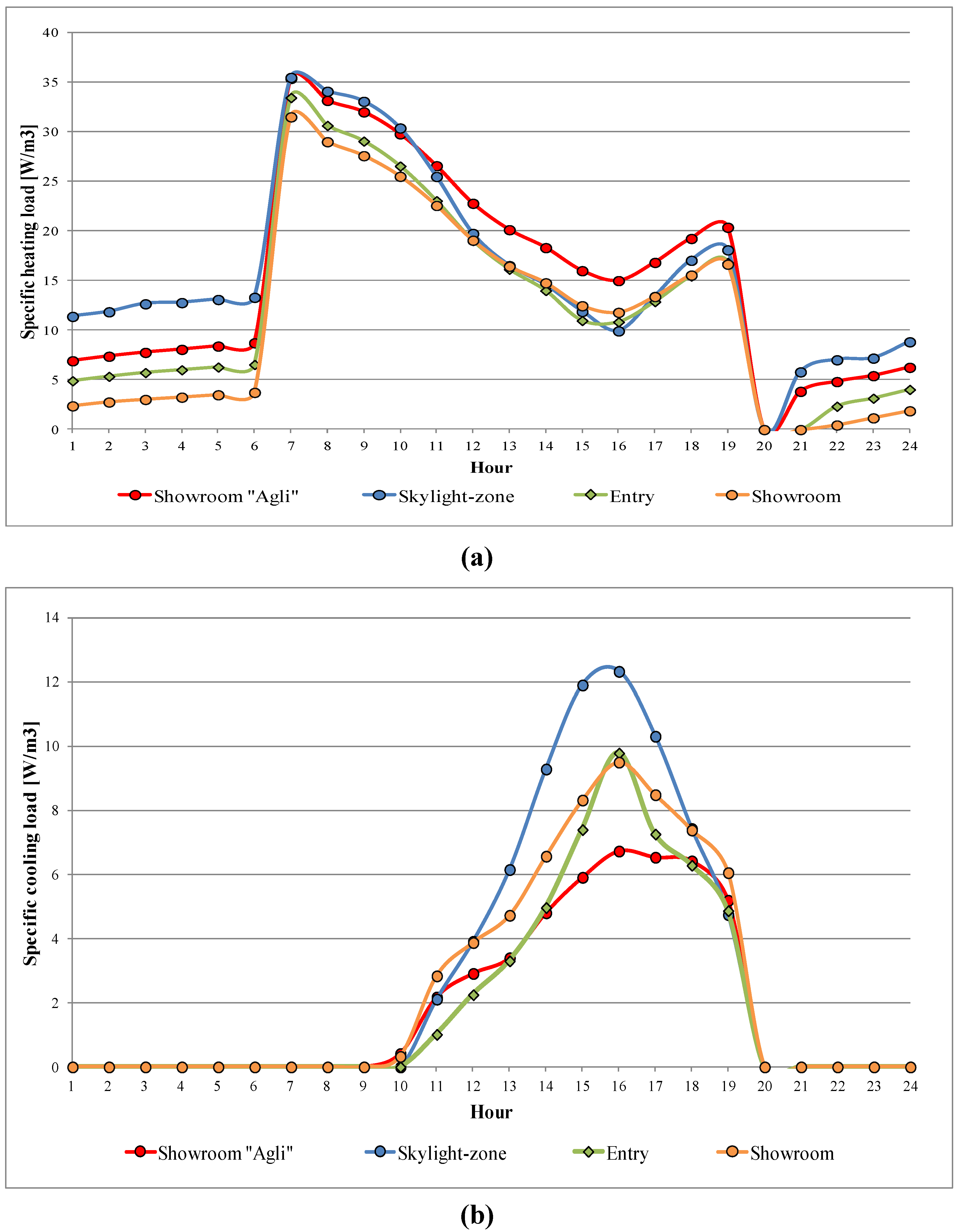
Specific hourly thermal load for two days representative of winter and summer seasons, respectively the 5 January (the coldest day of the year) and the 16 July (the hottest day), was calculated. When analyzing the specific hourly heating loads (
Figure 2a), the Via Degli Agli showroom and “skylight-zone” are characterized, during the day, by the highest specific energy consumption as compared to the other thermal zones.
On 16 July (
Figure 2b) the “showroom” and “skylight” zones are characterized by the highest values of hourly cooling load, because in the first hours of the day they are subjected to direct solar radiation, until the first hours of the afternoon when they are shaded by the surrounding buildings.
Results comparison supported a design proposal concerning the substitution of the previous glazed pitched roof with an active double glazed covering to control the incoming solar radiation and improve the energy performances of the cloister building system studied.
Figure 2.
Existing conditions: Specific hourly heating (a) and cooling loads (b) [W/m3].
Figure 2.
Existing conditions: Specific hourly heating (a) and cooling loads (b) [W/m3].
2.2. Project Proposal Analysis
An energy refurbishment solution, based on the substitution of the existing glazed pitched roof by an active double glazed covering, with a mechanical ventilation system, used as a thermal buffer, was proposed for solar radiation control, from the thermal and lighting points of view.
The cloister building system pursuant to restoration and refurbishment does have not high thermal inertia. The central courtyard is covered by a single glazed pitched roof, the vaults structure of the perimetral colonnade are closed by the existing shop-windows, then the only massive building components are the floor and the boundary walls of the church. To improve the thermal capacity and overall inertia of the cloister building system (274 m
2 total glazed surface and 950 m
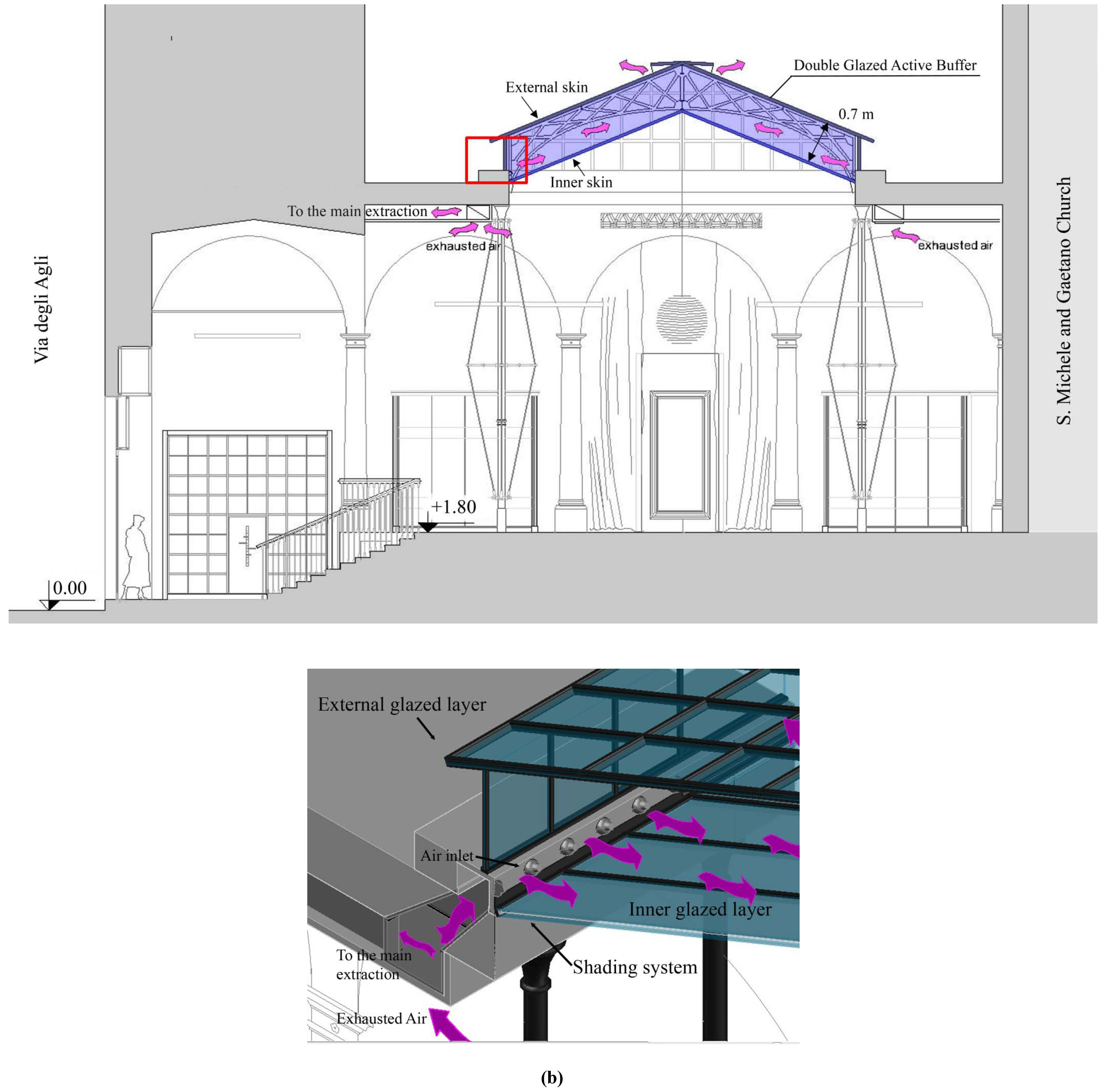
2 total opaque surface) a plant system composed of heating/cooling floor panels and a VAV plant system integrated with the active double glazed covering, was proposed. The air system was designed to control the hourly sensible and latent load variation during opening hours. The double glazed covering, 0.70 m total thickness, was designed with the insertion of a second glazed skin, towards the internal side of the existing roof. The active system concerns the connection between the VAV air ducts and the forced ventilation using a portion of the exhausted air flow rate of the VAV, as shown in
Figure 3.
The active double glazed covering was designed as a thermal buffer to control thermal loads of the underlying thermal zones, i.e., mainly for “skylight-zone” and the surrounding "showroom" zones.
Solar radiation control is guaranteed by a roller shading system located in the double glass, that set-up the inner layer of the double glazed covering. Taking into account the shading system, the transparency coefficient of the glass was assumed to be 30%.
Natural lighting distribution in the cloister system was simulated with dedicated commercial software [
20] assuming clear sky conditions at 13:00 of 16 July (common condition for summer period at mean latitudes, 40°–45°N, like Florence). The activation of the shading device provides a reduction of the average illuminance values, only due to natural light of 60% for the “showroom” and of 59% in the “skylight” zone.
Table 6 shows the lighting analysis results: the average illuminance values referred to the floor and the maximum illuminance levels concern the highest values among the maxima.
Table 6.
Illuminance value [klx] on the dealer, 16 July 13:00.
Table 6.
Illuminance value [klx] on the dealer, 16 July 13:00.
| | Average values | Maximum among the maxima |
|---|
| Thermal zones | No shaded | Shaded | Decreasing | No shaded | Shaded | Decreasing |
| Showroom | 14.89 | 5.96 | 60% | 58.26 | 42.62 | 27% |
| Skylight-zone | 42.38 | 17.35 | 59% | 58.47 | 27.04 | 54% |
| Via Degli Agli showroom | 6.64 | 6.14 | 8% | 43.27 | 42.64 | 1% |
Figure 3.
Cross-section of the Tornabuoni showroom with the Double Glazed Active Buffer (a) and 3D view of technical details of the system proposed (b).
Figure 3.
Cross-section of the Tornabuoni showroom with the Double Glazed Active Buffer (a) and 3D view of technical details of the system proposed (b).
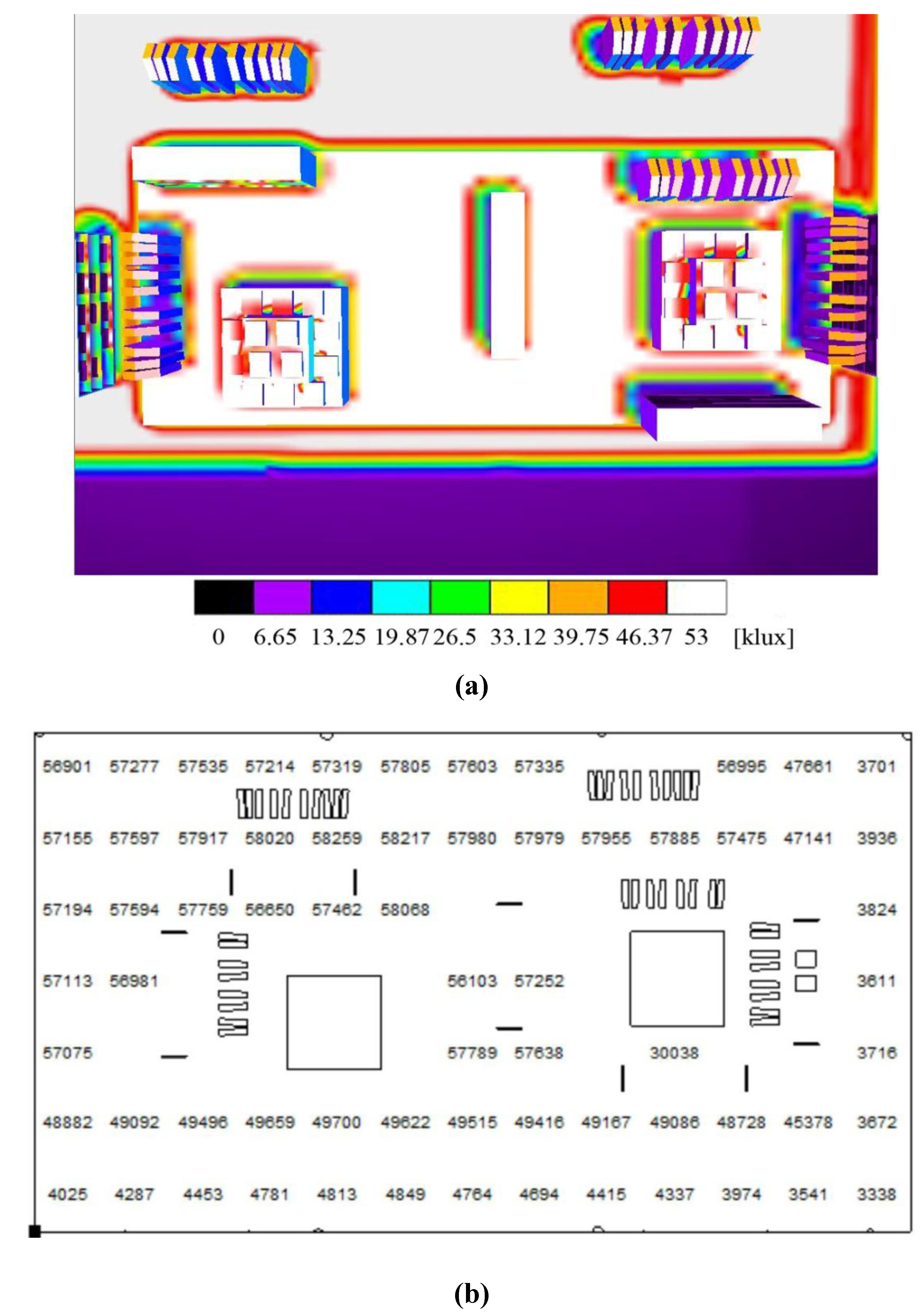
The illuminance level distribution for the “skylight-zone” and “showroom” without the shading devices are provided in
Figure 4a and the illuminance values at each mesh point in
Figure 4b.
Figure 4.
Illuminance levels (klx) distribution for the “skylight-zone” and “showroom” without the shading devices (a) and the illuminance values at each mesh point (b); 16 July, h 13.00.
Figure 4.
Illuminance levels (klx) distribution for the “skylight-zone” and “showroom” without the shading devices (a) and the illuminance values at each mesh point (b); 16 July, h 13.00.
The analysis of shadow distributions, due to the adjacent building over the year, and then during the hours when the thermal buffer is shaded, suggested the definition of a specific schedule for the roller screen shading operation time. From 10:00 to 17:00 in the period between 1 April and 30 September the skylight has to be shaded, to control the solar radiation and illuminance levels in the intermediate and summer seasons. From 1 October to 31 March, the proposed double glazed covering does not need to be shaded, to maximize the solar gains during the winter season.
Proportional thermal contributions, due to the optimized mixing between natural lighting and artificial lighting system, were provided by the lighting control system previously explained.
The buffer system connected to the VAV plant system, ensures a flow rate of 21 kg/s of exhausted air (with subsequent expulsion on the outside) from the “showroom” and “skylight” zones; the remaining exhausted air flow rate passes through a cross flow heat-exchanger for the outside air pre-treatment. The considered air flow rates are shown in
Table 7:
Table 7.
Fresh air flow and design air flow rates.
Table 7.
Fresh air flow and design air flow rates.
| | Volume [m3] | ACH [vol/h] | ACH [m3/h] | Fresh Air Flow rate [l/s] | Design ventilation rate [kg/s] | % respect to the overall air flow |
|---|
| Entry | 120 | 2 | 240 | 67 | 200 | - |
| Showroom | 2064 | 2 | 4128 | 1147 | 3440 |
| Skylight-zone | 978 | 2 | 1956 | 543 | 1630 |
| Via Degli Agli showroom | | | | 247 | 740 |
| Storage | | | | 98 | 293 |
| Fitting room | | | | 212 | 635 |
| Cavity ventilation | 66 | - | - | 21 | - | 1 % |
| Air flow on the heat exchanger | | | 3864 | 1732 | - | 99 % |
| Total | 4266 | | 6084 | 1753 | | |
This ventilation strategy allows one to obtain a thermal buffer system with a stable temperature between the thermal zones and the external ambient: the inside air temperature is heated during winter and cooled during summer. The thermal zones below, interact with thermal buffer and the external climatic fluctuations. Due to the active double glazed covering, the thermal loads are controlled and the hourly thermal loads have a regular trend.
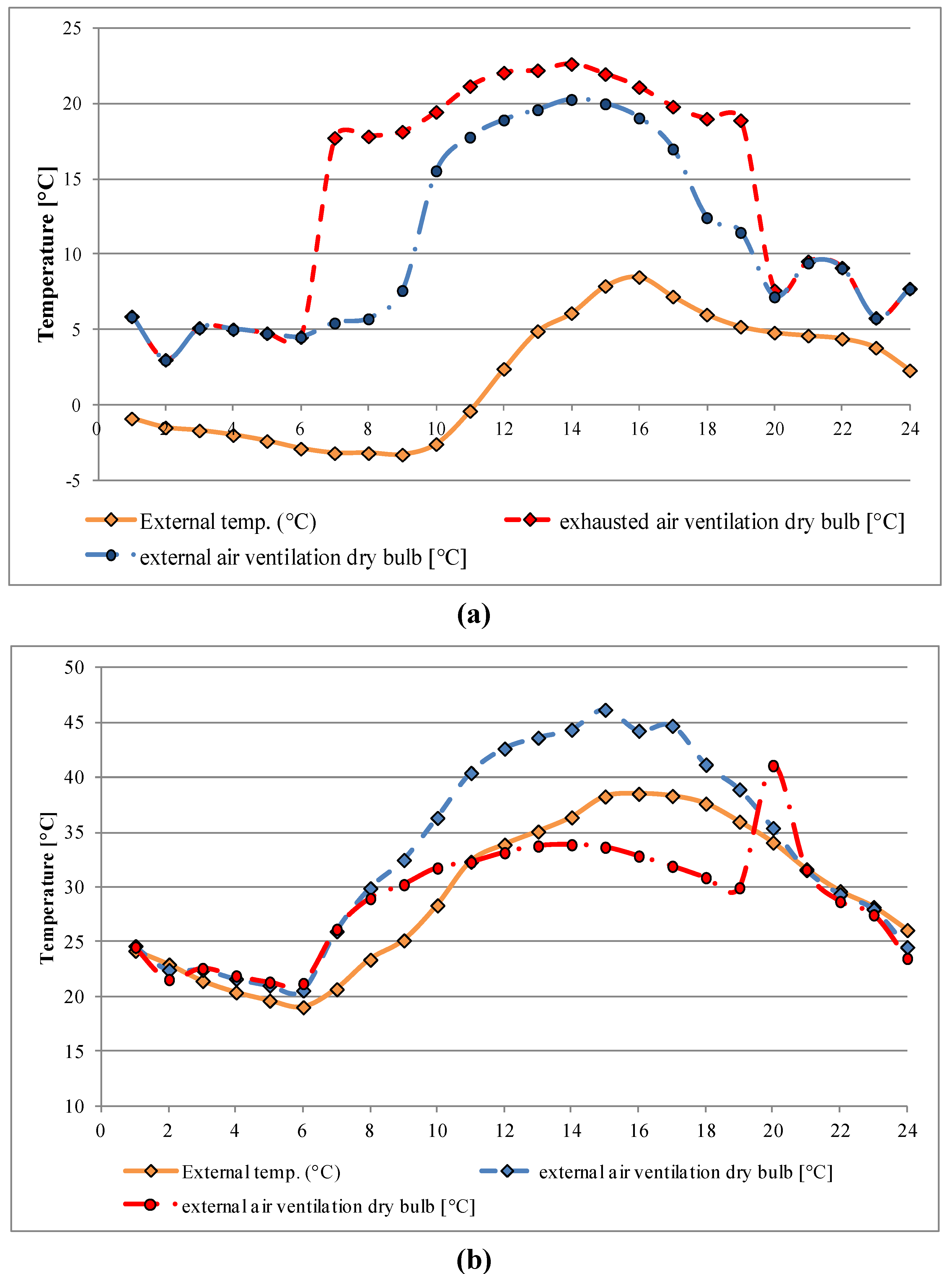
The air flow rate for the ventilation of the double glazed covering (thermal buffer), is very low compared to the overall air flow rate (1%), but sufficient to stabilize indoor thermal-hygrometric conditions. To determine the optimal ventilation air flow rate of the cavity, a sensitivity analysis was performed (
Figure 5). Starting from a minimum air flow value of 4.5 kg/s and increasing it by two and three times the air flow (until 21 kg/s) the air temperature obtained inside the cavity was constant and with values close to those of the internal zones.
Figure 5.
Air temperature in the active thermal buffer: 5 January (a)–16 July (b).
Figure 5.
Air temperature in the active thermal buffer: 5 January (a)–16 July (b).
A comparison between the solutions proposed that uses exhausted air, and a “traditional” ventilation system that uses total external air for the double glazed covering, was carried out.
The “traditional” solution suggests, during winter, the absence of ventilation to maximize the greenhouse effect and thermal resistance of the building component. In order to limit the overheating phenomena, a forced ventilation system must be applied for intermediate and summer seasons [
21].
Hourly building-plant system energy analysis, using TAS [
19], was carried out for all the year and typical summer and winter days. A comparison between the proposed ventilation strategy (with total exhaust air) and the traditional solution (with total external air), using the same ventilation air flow rates (
Table 6) was made. The efficiency of these two ventilation techniques was analyzed with the estimation of the heating and cooling load variation for “skylight-zone” and “showroom” zone, directly influenced by the thermal behavior of the double glazed covering (
Figure 6,
Figure 7).
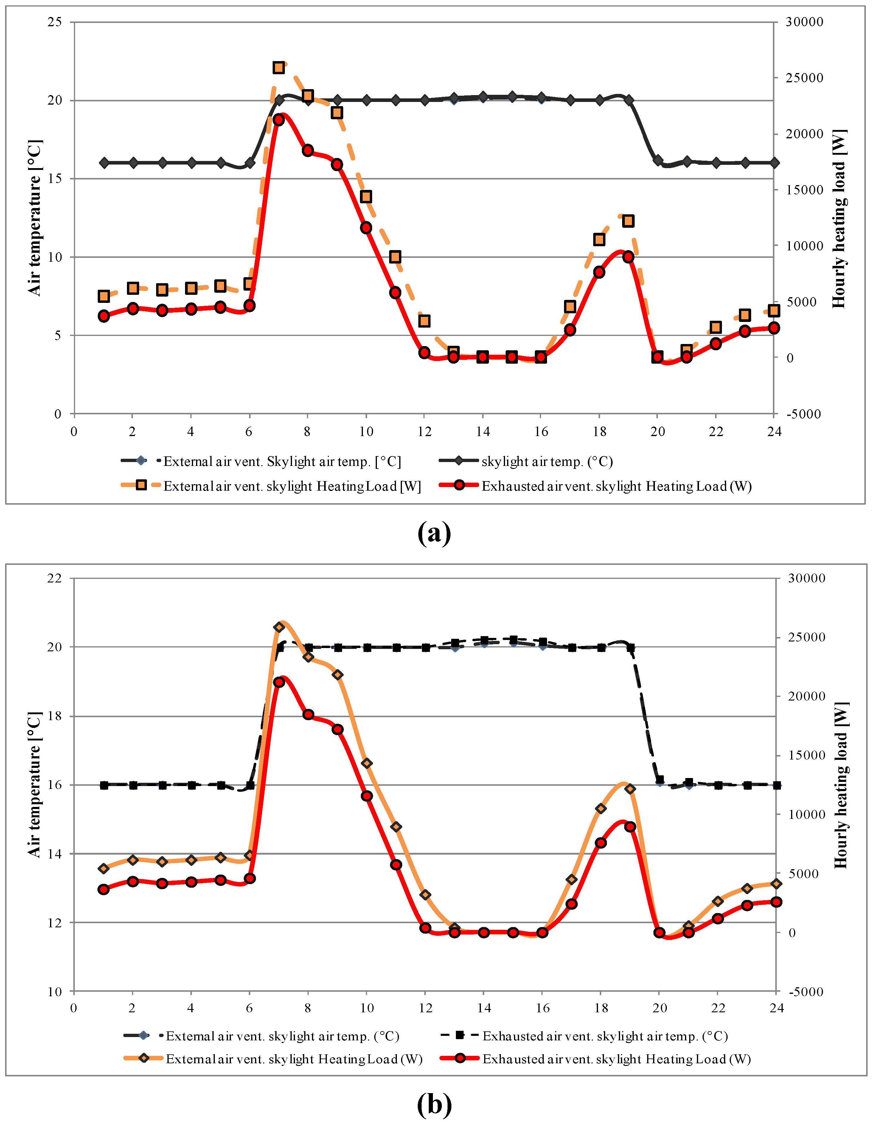
In the winter season, the hourly heating loads highlight how the "active" thermal buffer can provide best energy performances, compared with the traditional solution, with a reduction of the peak heating load values for the two thermal zones (
Figure 6).
Figure 6.
Hourly heating loads for different ventilation solution comparison: “skylight-zone” (a) and showroom (b).
Figure 6.
Hourly heating loads for different ventilation solution comparison: “skylight-zone” (a) and showroom (b).
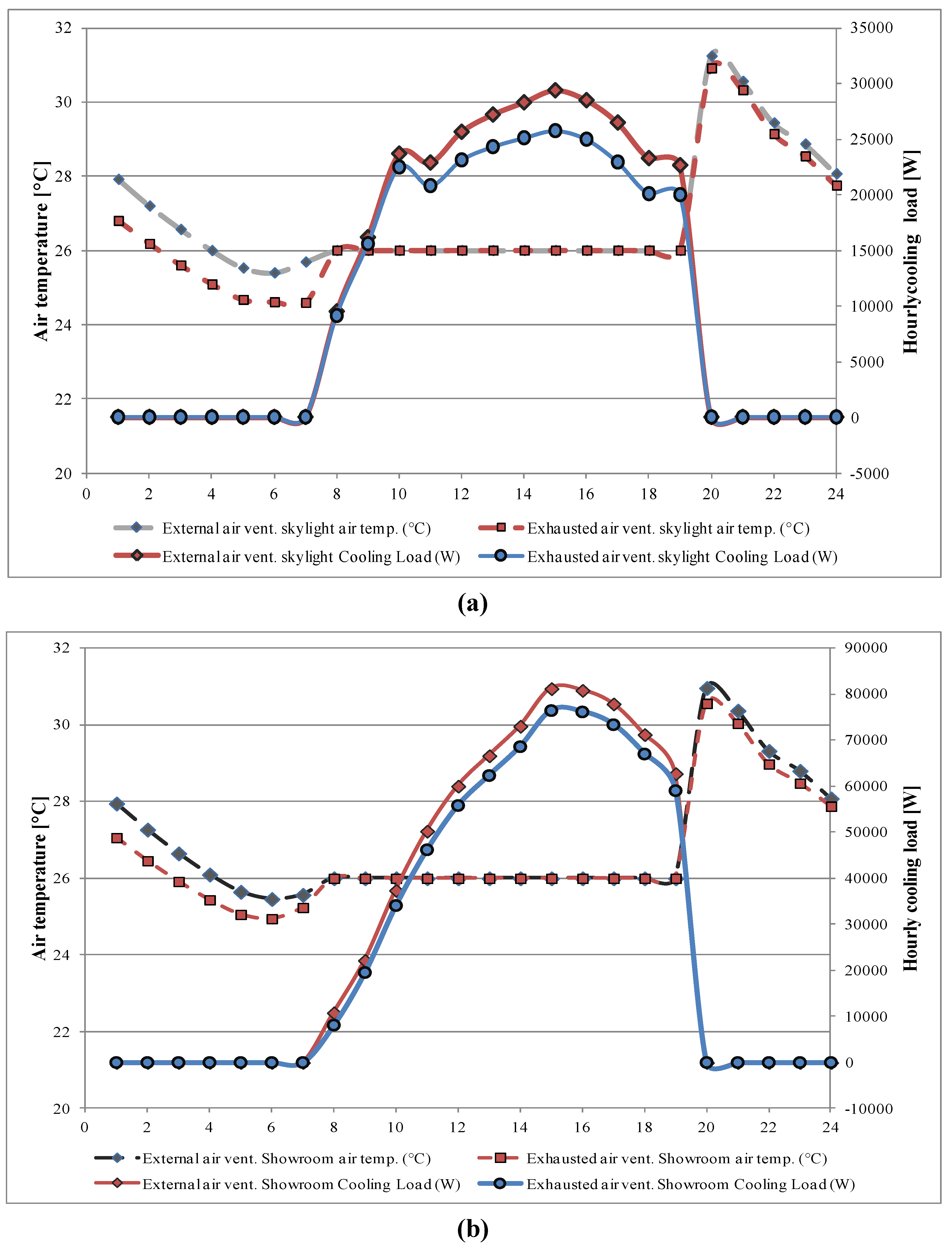
The active thermal buffer contribution is clearer in the summer season, when the ventilation system of the glazed cavity using exhausted air allows an important reduction of the hourly cooling loads (
Figure 7). The exhausted air temperature is lower than the external one: the ventilation using this cold air allows maintenance of a stable temperature in the buffer, reducing heat exchanges through the glazed surfaces.
Figure 7.
Comparison between hourly cooling loads for different ventilation of the skylight (a) and showroom (b) thermal zones.
Figure 7.
Comparison between hourly cooling loads for different ventilation of the skylight (a) and showroom (b) thermal zones.
In addition, during the winter season (
Figure 8a) the cavity ventilation with indoor exhausted air maximizes the greenhouse effects with a reduction of about 4 hours necessary for the cavity heating.
Figure 8.
Hourly air temperature values of the thermal buffer, 5 January (a) and 16 July (b).
Figure 8.
Hourly air temperature values of the thermal buffer, 5 January (a) and 16 July (b).
Our suggested solution allows limitation of an overheating risk, during the summer season, and a reduction of the air temperature value of the internal zones, also in the presence of very high solar radiation values (800 W/m
2;
Figure 8 b). The overheating risk of the buffer cavity occurs in the early hours of the afternoon, also when the external air reaches 34 °C.
In these conditions the air temperature inside the buffer cavity reaches 45°C. A forced ventilation of the cavity with 26 °C air temperature, allows an efficient control of the buffer cavity air temperature and heat exchange reduction between the thermal buffer and zones below.
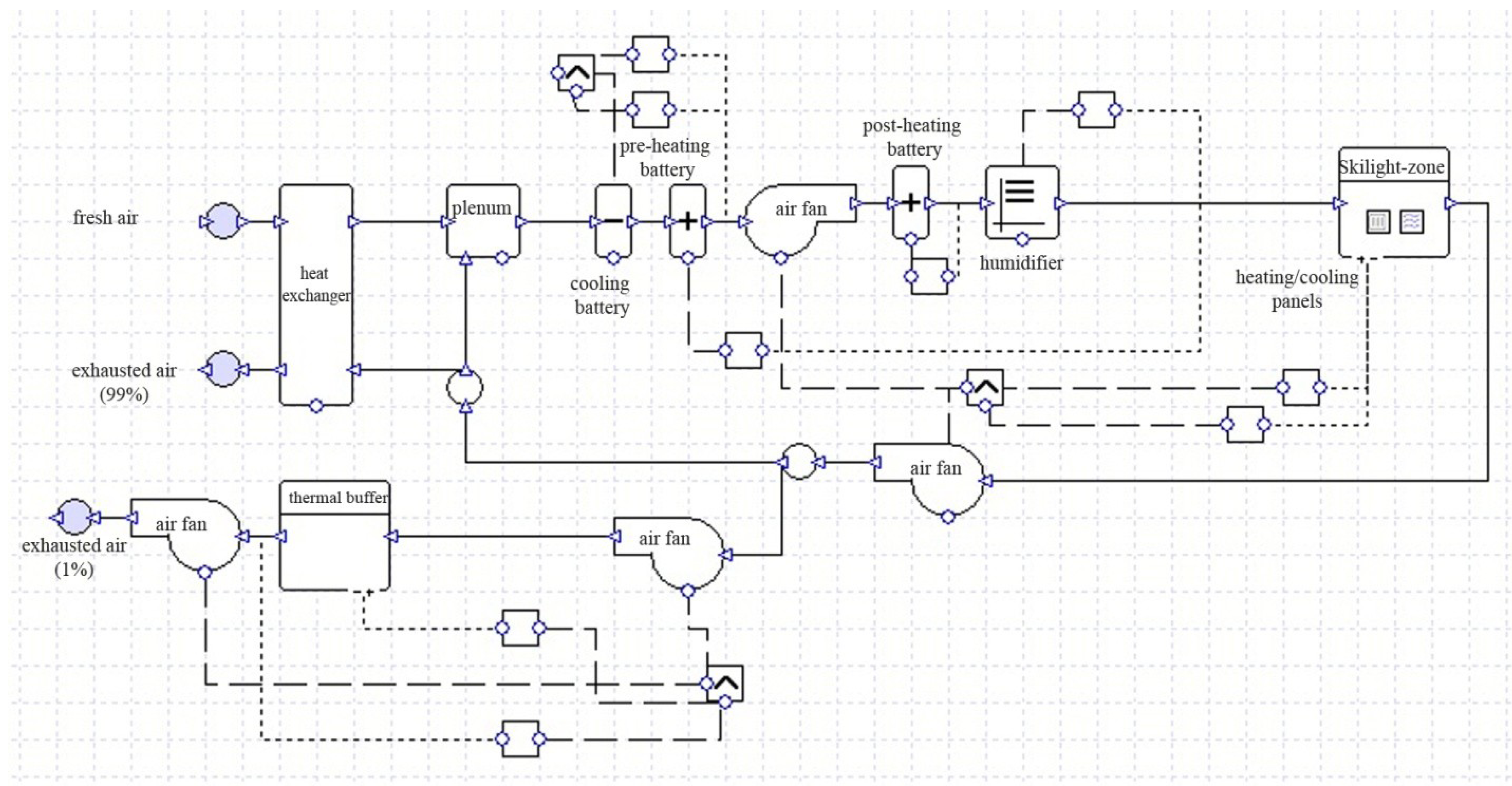
2.3. Integrated VAV-heating/cooling Panel Settings.
The scheme of the proposed plant system is shown in
Figure 9. The energy performances of the plant system, sized on the heating and cooling peak loads, were evaluated with a whole building energy analysis using [
19,
22].
Figure 9.
Scheme of the proposed plant system.
Figure 9.
Scheme of the proposed plant system.
Each thermal zone is provided with a heating/cooling panel, schematized as zone terminal with an appropriate “proportion radiant” factor, as suggested in [
23]: radiators for heating (radiant heating 0.68) and fancoils for cooling (radiant cooling 0.58). This equipment is connected to a thermostat, for indoor air temperature control. The VAV system ensures a minimum fresh air flow rate and, with an air recirculation system, a design air flow rate (
Table 4) to control the latent thermal loads of the considered zone.
The air flow rates are regulated by two air temperature sensors connected to the thermal zone to regulate the air flow fans between the fresh and the design air rate.
The inlet air condition guarantees the internal relative humidity values between the maximum (60%) and minimum (40%) value, to control the hourly variation of the latent heat loads due to people presence. A cross-flow heat exchanger, with an efficiency of 0.70 [
23], allows a first heat recovery for the external air. The plant of the thermal zone is considered in operating conditions from 8:00 to 20:00 for six days each week.
During the winter season (operating hours from 7:00 to 20:00) a pre-heating battery, controls that the air temperature values, are up to 22 °C ± 1 °C [
21]. A humidifier, connected to the air inlet, guarantees the air relative humidity values from 40% to 50% [
23].
In the summer season the cooling battery, makes sure that the air temperature values are between 23 °C and 24 °C and the air relative humidity value is lower than 50%. A post-heating battery ensures that the inlet air temperature value is 24 °C ± 1 °C.
The exhaust air passes with a fan through the active thermal buffer. Two sensors are connected to the double glazed buffer cavity:
a first sensor, for the flow rates control, to ensure a minimum flow rate (10 l/s), during the operating hours, and the exhausted air maximum flow rate (21 l/s);
a second sensor, for the air temperature control, to guarantee the internal air temperature values at 35 °C ± 2 °C.
2.3.1. Results and Discussion: Energy Consumption Reduction
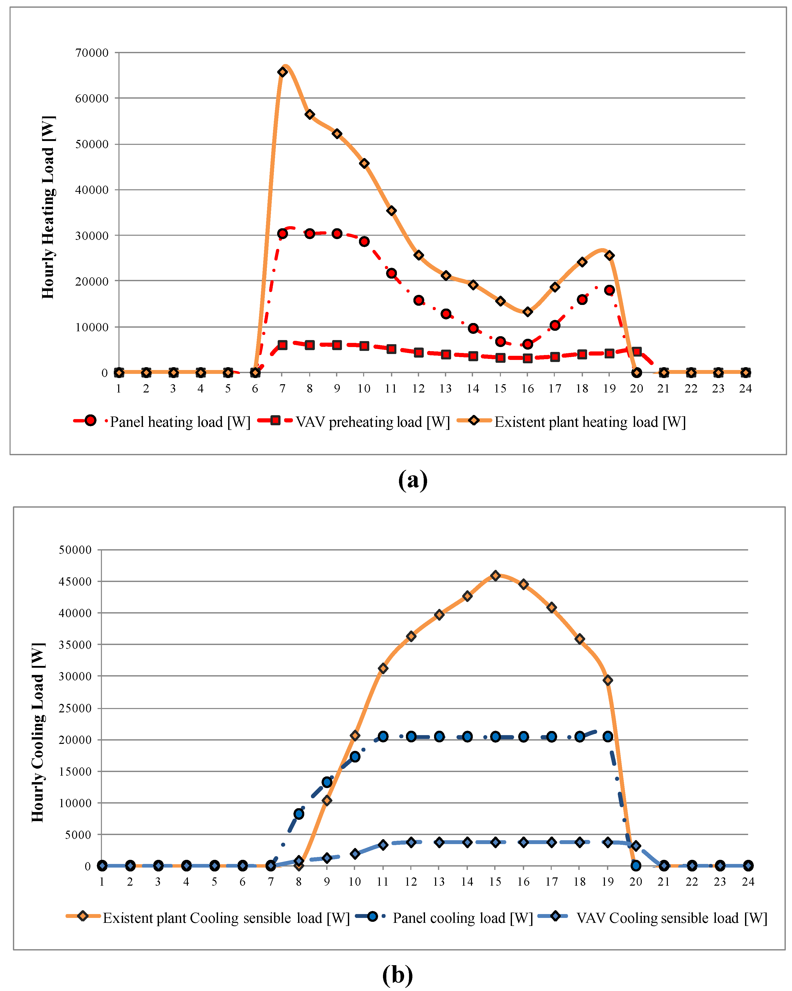
Hourly thermal load calculation of the proposed plant system, in working conditions, was carried out for the coldest day of winter (5 January) and hottest day of summer (16 July) season. Hourly heating/cooling loads for the “skylight” thermal zone, the most involved zone by the proposed solution, were provided and compared with the thermal loads of existing conditions (
Figure 10 a,b
Figure 10.
Skylight: (a) hourly heating and (b) cooling loads.
Figure 10.
Skylight: (a) hourly heating and (b) cooling loads.
On the coldest day (
Figure 10a), the proposed plant shows the lower value of the peak heating load (20 kW) compared to the existing conditions (68 kW). This is due to the thermal inertia of the heating panel system that allows, for the first hours in the morning, a comfortable indoor temperature with reduced heating loads compared to the existing conditions. On the hottest day (
Figure 10b) the thermal buffer presence with the activation of the roller screen solar shading system, and the cooling panel system inertia, allows an important reduction of the hourly cooling loads, at the same time as a peak cooling load value reduction from 45kW to 20kW.
A comparison between the solar heat gains and daily heating/cooling loads is provided in
Table 8. On the coldest day, the second glazed layer of the thermal buffer provides a reduction of the solar gains in the “showroom” and in the “skylight” thermal zones, respectively of 29% and 42%. The daily heating load value of the “showroom” thermal zone is similar to the one provided by the present conditions, because during the winter season the surrounding building overshadows this zone until 14:00. In particular, during winter the “showroom” does not benefit from solar gain. Thermal buffer efficiency, from the heat transfer point of view, is more important for the “skylight” thermal zone, due to a 28% decrease in daily heating load.
Table 8.
Daily solar gain and heating/cooling loads comparison.
Table 8.
Daily solar gain and heating/cooling loads comparison.
| | Showroom | Skylight |
|---|
| 5th January | decrease | 16 July | decrease | 5 January | decrease | 16 July | decrease |
|---|
| Existing | proposed | | Existing | proposed | | Existing | proposed | | Existing | proposed | |
|---|
| Solar gains [kW] | 45 | 32 | 29% | 135 | 43 | 68% | 88 | 51 | 42% | 511 | 200 | 61% |
| Daily heating load [kW] | 688 | 698 | 1% | - | - | - | 420 | 301 | 28% | - | - | - |
| Daily cooling load [kW] | - | - | - | 608 | 262 | 57% | - | - | - | 377 | 262 | 30% |
On the hottest day and during the whole summer season, the solar shading device allows an important reduction of the solar heat gain and daily cooling load, respectively of 60% and of 30% for the “skylight zone”. This is mainly due to the constant value of the air temperature (35 °C) inside the thermal buffer that provides important heat exchanges.
In the “showroom”, that is always exposed for the early afternoon hours to direct solar radiation through the existing glazed pitched roof, the proposed solution with an active double glazed covering allows a 57% reduction of the daily cooling load. Our solution also provides, for all the year, significant energy savings and an important thermal load reduction: 45% for the annual heating energy consumption (from 128 MWh to 69.9 MWh) and 39% for the annual cooling energy consumption (from 61.9 MWh to 37.8 MWh), as shown in
Table 9.
Table 9.
Annual Energy consumptions.
Table 9.
Annual Energy consumptions.
| | Existing plant | Existing plant energy consumption | Proposed plant | Proposed plant energy consumption | Annual reduction |
|---|
| Showroom | Skylight-zone | Showroom | Skylight-zone |
|---|
| Heating [MWh] | 65.6 | 43.1 | 128.2 | 62.6 | 26.9 | 69.9 | 45% |
| Cooling [MWh] | 26.5 | 20.2 | 61.9 | 35.4 | 17.6 | 37.8 | 39% |
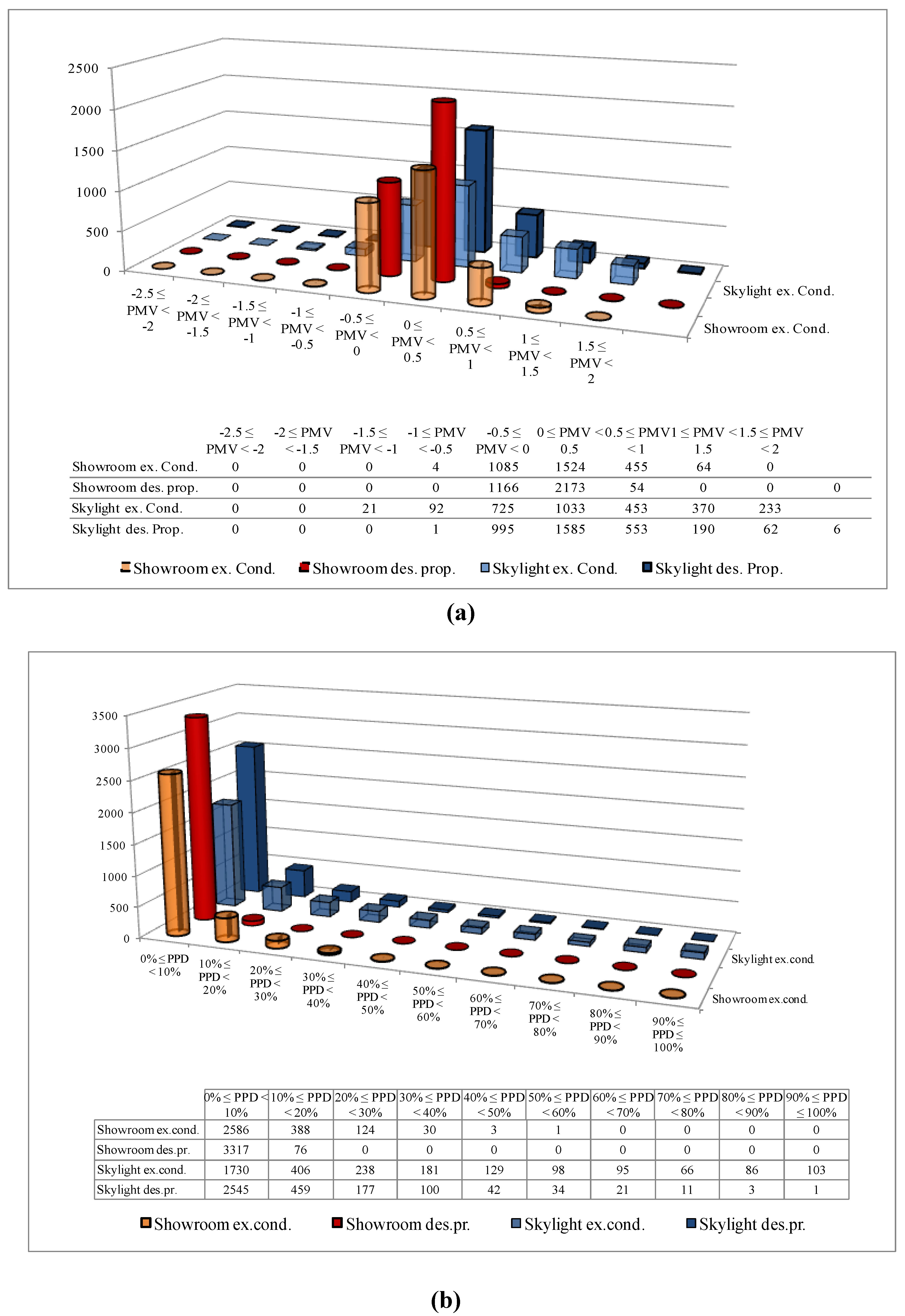
2.3.2. Results and Discussion: Thermal Comfort Analysis
The plant refurbishment solution, proposed, based on an active thermal buffer integrated with a VAV air system and heating/cooling panels was analyzed from the thermal comfort point of view. This analysis allows one to evaluate the efficiency of the buffer also designed to control the natural and artificial lighting optimal mixing. Referring to the hourly energy analysis results obtained for the building plant system proposed solution, the Predicted Mean Vote (PMV) and the Predicted Percentage Dissatisfied (PPD) indexes were evaluated using [
24].
The indoor climatic conditions were assumed corresponding to the hourly values of the internal air temperature and relative humidity. The mean air velocity was fixed at the constant value of 0.12 m/s for winter period and 0.15 m/s for summer period. The indexes were evaluated assuming as thermal resistance of people clothing, 1.2 clo for winter and 0.8 clo for summer season [
24]. The frequencies of the annual hours for which the PMV and PPD were evaluated for the two zones (“showroom” and “skylight-zone”) are given in
Figure 11.
The improvement of the PMV and PPD frequency trend (
Figure 10) is comparable for “showroom” and “skylight” thermal zones considering first existing conditions and then the proposed solution. Our integrated building-plant solution shows values for the PMV index never beyond the range −0.5 ÷ 0.5 (
Figure 11a) and for PPD index (
Figure 11b) almost lower than 10%.
Figure 11.
(a) PMV (b) PPD indexes.
Figure 11.
(a) PMV (b) PPD indexes.


