
Coal Mine Rock Burst and Coal and Gas Outburst Perception Alarm Method Based on Visible Light Imagery

School of Artificial Intelligence, China University of Mining and Technology-Beijing, Beijing 100083, China
*
Author to whom correspondence should be addressed.
Sustainability 2023, 15(18), 13419; https://doi.org/10.3390/su151813419
Submission received: 19 August 2023
/
Revised: 3 September 2023
/
Accepted: 4 September 2023
/
Published: 7 September 2023
(This article belongs to the Special Issue Hazard Control and Emergency Rescue in Underground Engineering—2nd Edition)
Abstract
:To solve the current reliance of coal mine rock burst and coal and gas outburst detection on mainly manual methods and the problem wherein it is still difficult to ensure disaster warning required to meet the needs of coal mine safety production, a coal mine rock burst and coal and gas outburst perception alarm method based on visible light imagery is proposed. Real-time video images were collected by color cameras in key areas of underground coal mines; the occurrence of disasters was determined by noting when the black area of a video image increases greatly, when the average brightness is less than the set brightness threshold, and when the moving speed of an object resulting in a large increase in the black area is greater than the set speed threshold (V > 13 m/s); methane concentration characteristics were used to distinguish rock burst and coal and gas outburst accidents, and an alarm was created. A set of disaster-characteristic simulation devices was designed. A Φ315 mm white PVC pipe was used to simulate the roadway and background equipment; Φ10 mm rubber balls were used to replace crushed coal rocks; a color camera with a 2.8 mm focal length, 30 FPS, and 110° field angle was used for image acquisition. The results of our study show that the recognition effect is good, which verifies the feasibility and effectiveness of the method.
1. Introduction
As China’s main energy source, coal is the ballast stone used for China’s energy security and stable supply. As major disaster accidents in coal mines, rock bursts and coal and gas outbursts seriously threaten the safety production of coal mines in China [1,2,3]. The timely detection of disasters and issuing of alarm signals are key measures for evacuating underground personnel, dredging blocked roadways, rescuing people in distress, avoiding secondary disasters, and reducing casualties and property losses [2,3,4,5]. In researching rock bursts and coal and gas outbursts, the properties, structure, and stress changes of coal rocks have been studied extensively. At present, the main methods of disaster monitoring are rock mechanics methods, which are mainly based on drilling cuttings and stress monitoring. The geophysical methods mainly include the microseismic method, acoustic emission method, and electromagnetic radiation method [6,7,8,9,10,11,12]. There have also been disaster hazard studies based on physical experiments using images [13,14,15,16]. However, the mechanism of such disasters is currently unclear, China’s geological conditions are complex and diverse, and disasters still occur occasionally. At present, the monitoring, early warning, and prevention of disasters cannot meet the safety production needs of China’s coal mines. Therefore, it is necessary to study the perception alarm methods of coal and gas outburst disasters in coal mines.
In addition, the current research has mainly focused on the identification of coal rock states during the preparation, development, and propagation of rock burst and coal and gas outburst disasters, but has not yet emerged in the roadway space [17,18,19,20,21,22], while there are few studies on the characteristics of the large numbers of coal rocks thrown into working faces and roadways after disasters [23,24,25,26,27,28,29,30]. This paper reports a study on the specific implementation of the perception alarm method for rock burst and coal and gas outburst disasters based on the color-image-based disaster perception alarm method proposed in the literature [30]. Therefore, the author of the present study proposes a coal mine rock burst and coal and gas outburst perception alarm method based on visible light imagery, which perceives the color, brightness, and velocity characteristics created by the large number of coal rocks thrown into the working face and roadway space when a disaster occurs using color video images in the monitoring area, and provides simple and distinct information about the large number of coal rocks thrown. This method has the advantages of being non-contact and having a wide monitoring range, having simple deployment and installation, convenient use and maintenance, and being low cost. It can provide a new method and concept for detection alarms of rock burst and coal and gas outburst disasters in coal mines.
2. Disaster Characteristics and Perception Methods
When rock burst and coal and gas outburst disasters occur, large numbers of coal rocks are thrown into the working faces and roadway spaces, resulting in velocity and color characteristics different from those of the normal working conditions. Images can be used to monitor the color, brightness, and velocity characteristics of disasters to determine the occurrence of disasters, and then methane concentration characteristics can be used to distinguish and trigger alarms for rock burst and coal and gas outburst accidents.
2.1. External Characteristics of Disasters
Although the internal disaster-causing mechanisms of rock burst and coal and gas outburst disasters differ, their external characteristics are similar.
Coal mine underground equipment is generally not black, as can be seen in tunneling machines, coal mining machines, transfer machines, crushers, hydraulic supports, belt conveyors, shuttle cars, air ducts, etc., where the general appearance is orange, orange-red, deep-red, gray-white, or blue. According to the distinct color differences between coal rocks thrown by disasters, which are mainly black, and non-black equipment in coal mines [30], with non-black equipment in coal mines as the background, color cameras are used to capture coal rocks thrown by disasters. The capturing range of disaster-thrown coal rocks can be limited to the areas where the black areas of color images increase significantly. The color characteristics of typical equipment in underground coal mines are shown in Figure 1.
When rock bursts and coal and gas outbursts occur, a large number of broken coal rocks are thrown in a short time, and the maximum speed of coal rocks thrown out by the disasters is about 50 m/s [31,32], which is much faster than the normal speed of coals falling and the movement speed of underground personnel, rubber wheel vehicles, coal shearers, and roadheaders (the maximum speed is about 13 m/s) [29,30,33]. Color cameras can be used to identify the above speed difference characteristics for disaster detection and alarm. The speed range of coal rocks thrown by disasters can be limited to V > 13 m/s.
When rock bursts and coal and gas outbursts occur, they cannot generate high brightness, while gas and coal dust explosions can cause the high short-term velocity of objects in roadway space accompanied by high brightness, and the interference of gas and coal dust explosions can be eliminated according to brightness characteristics [30,34].
2.2. Video Image Perception Method
Coal mine dust falls on equipment; long-term accumulation can cause gas and coal dust explosions. The “Coal Mine Safety Regulations” stipulate that the dust of underground coal mine equipment should be cleaned periodically [33], which also ensures the intact color characteristics of underground coal mine equipment and creates favorable conditions for extracting the color characteristics of rock burst and coal and gas outbursts.
Rock bursts and coal and gas outbursts can cause damage to hundreds of meters of roadway and production equipment in a short, rapid, and violent manner, so it is necessary to arrange disaster-sensing devices at multiple points. The disaster-sensing devices close to the disaster source may be damaged, but the remote and undamaged devices can ensure that the disaster-sensing system can still effectively detect and alarm the rock burst and coal and gas outburst when the disaster occurs. The intrinsically safe explosion-proof disaster-sensing device can be installed at the end, middle, and entrance of the driving roadway; installed on the mining face; installed at the entrance and middle of the air inlet roadway; installed at the entrance and middle of the return air roadway; and installed at the auxiliary transportation lane, main transportation lane, and other locations.
Gas is released when rock bursts and coal and gas outbursts occur. However, when coal and gas outbursts occur, the amount of gas released, gas concentration in the roadway, speed, and spread range are far greater than when rock burst occurs. Thus, using methane sensors in multiple locations, it can sense whether the methane concentration has significantly increased over a wide range. When methane concentrations are detected at different locations, such as the mining face, inlet roadway, return roadway, and total return roadway, all increase significantly or at the alarm value, a coal and gas outburst is perceived; otherwise, a rock burst is perceived.
In order to accurately identify coal burst and coal and gas outburst disasters in coal mines, aiming at the color and velocity characteristics caused by a large number of coal rocks thrown into the working face and roadway space when the disaster occurs, a coal mine rock burst and coal and gas outburst perception alarm method based on visible light imagery is proposed. The main steps are as follows:
- (1)
- Color cameras with fill lights are arranged at multiple points on or near the roof of the coal mining face, the top of the support of the mining face, and the roof of the roadway or near the roof, etc., to collect color video images in the monitoring area in real time, and methane sensors arranged at multiple points are used to monitor the environmental methane concentration in the monitoring area [30,35];
- (2)
- Against the background of equipment with distinct color differences from the disaster-thrown coal rocks, monitor and identify whether the color video images have a black area change;
- (3)
- When the color cameras detect a significant increase in the black area at the end, middle, and entrance of the driving roadway; the mining face; the entrance and middle of the air inlet roadway; the entrance and middle of the air return roadway; the main transportation roadway; or the auxiliary transportation roadway, indicating the color characteristics at the time of disaster occurrence, then the average brightness of the color video image is monitored and recognized. Otherwise, whether there is a black area change in the color video image is continually monitored and identified where applicable;
- (4)
- If the average brightness is less than the set brightness threshold, it indicates no abnormal brightness, and the interference of gas and coal dust explosion is eliminated [30,34]; thus, the object movement speed that causes a significant increase in the black area is identified. Otherwise, the color video image is continuously monitored to identify whether the black area changes;
- (5)
- If the movement velocity is greater than the set velocity threshold (V > 13 m/s), it indicates that there is a velocity characteristic of coal rocks thrown due to the disaster. Therefore, monitoring and identifying the environmental methane concentration in the monitoring area is performed. Otherwise, the color video image is continuously monitored to identify whether the black area changes;
- (6)
- The methane sensors monitor whether the methane concentration in the monitoring area increases rapidly or reaches the alarm value. When multiple different locations, such as the mining face, air inlet tunnel, air return tunnel, and total air return tunnel, detect a significant increase or reach the alarm value, the alarm will be issued for a coal and gas outburst, and vice versa, where the alarm will be issued for a rock burst;
- (7)
- If the emergency response is activated after the alarm of coal and gas outbursts, then the alarm is canceled and there is continued monitoring and identification as to whether there is a black area change in the color video image. Otherwise, the disaster alarm is continued and the emergency response is activated; if the emergency response is activated after the alarm of rock burst, then the alarm is canceled and there is continued monitoring and identification as to whether there is a black area change in the color video image. Otherwise, the disaster alarm is maintained and the emergency response is activated.
The coal mine rock burst and coal and gas outburst perception alarm method based on visible light imagery is shown in Figure 2.
3. Specific Implementation of the Image Perception Method
The specific implementation method of disaster image perception proposed in this paper can be divided into four parts: color change feature recognition, average brightness feature recognition, moving speed feature recognition, and comprehensive disaster recognition alarm.
3.1. Color Change Feature Recognition
When a disaster occurs, a large number of coal rocks, which are mainly black, are thrown out, causing non-black equipment in the monitoring area that has a significant color difference from the coal rocks to be obscured, covered, or buried by the thrown-out coal rocks, and thus, the color of the non-black image in the monitoring area will partially or completely change to the color of the coal rocks (black).
Regarding the color change feature recognition part, this paper first uses the HSV (hue, saturation, value) color model image to segment the black (coal rock color) area within the surveillance range and then uses the Vibe algorithm to identify the area where the black area within the surveillance range has increased significantly, which is the identified area with a large change in image color caused by the suspected disaster-thrown coal rocks.
HSV (hue, saturation, value) is a color space based on the intuitive properties of color created by A. R. Smith in 1978, also known as the Hex Cone Model. There are three color parameters in this model: hue (H), saturation (S), and lightness (V). The relational equation for the conversion of color images from the RGB (red, green, blue) color model to the HSV color model is as follows [36] (where R, G, and B are normalized):
The corresponding parameter range of the HSV color model is set to segment the image’s black areas in a targeted manner. The Vibe algorithm is then used to identify the areas where the black area varies within the monitored range.
In the Vibe algorithm model, all background points are stored in the sample set, and it is determined whether each new pixel value belongs to a background point by comparing it with the sample set. That is, a new observation should be closer to the sampled values in the sample set if it belongs to a background point [37].
Specifically, the background pixel samples are randomly selected using the 8-neighborhood method, with denoting the value obtained by the pixel at image x in a given Euclidean color space, and each background pixel is modeled by the set of n background samples:
Classify the pixel value according to the model . Define a sphere with as the center and radius R. Compare it with the closest value in the sample and write down the set threshold as T. If
it means that the pixel point is the background point and vice versa for the foreground point.
Finally, whether there is a large increase in the number of pixels of the former attraction is determined, and if there is a large increase, it means that a large increase in the black area occurs within the monitoring area. That is, the color change feature of the disaster appears, and the next step of the average brightness feature recognition is carried out; otherwise, the Vibe algorithm is continuously used to monitor the black area change of the image.
3.2. Average Brightness Feature Recognition
With regard to the average luminance feature recognition, this paper uses the HSV color model to analyze whether the average V value (luminance) of the color video image is less than the set luminance threshold to determine whether the image has abnormal luminance.
Using the HSV color model in Section 2.1 to analyze whether the average V value (luminance) of the image is less than the set luminance threshold to determine whether the image has abnormal luminance, the relationship [36] is determined as follows:
where (x, y) is the coordinate of the pixel point in the image, B (x, y) is the pixel luminance at the coordinate point of (x, y), N is the total number of image pixels, Bave is the average image luminance value, and BT is the set luminance threshold.
If the average luminance of the image in the monitored area is monitored to be less than the set luminance threshold, the next step of moving speed feature recognition is carried out; otherwise, the Vibe algorithm is continuously used to monitor the image’s black area change.
3.3. Moving Speed Feature Recognition
When a rock burst or coal and gas outburst occurs, a large number of coal rocks are thrown into the mining face and roadway space, and the thrown coal rocks are different from the original coal rocks of the roadway under normal working conditions, with the abnormal characteristic of higher speed.
Regarding moving velocity feature recognition, this paper takes the non-black equipment under the coal mine with distinct color differences from the disaster-thrown coal rocks as the background and uses the color camera to monitor whether the velocity of a large number of thrown coal rocks in the area is larger than the set velocity threshold (V > 13 m/s) to determine whether a velocity abnormality occurs.
In order to achieve the largest possible monitoring range of individual cameras while not affecting the speed measurement of individual cameras, the optimal tilt angle of color cameras to meet the following conditions is a maximum of the following:
where is the forward tilt angle of the color camera relative to the vertical downward, °; is half of the color camera’s field of view along the camera’s optical axis, °; is the height of the color camera installation position from the alley floor, m; is the focal length of the color camera, m; is the length of one pixel in the video image, m; is the time of one frame elapsed in the video image, s; is the real moving speed corresponding to the object at the farthest end of the color camera surveillance area, when moving one pixel-length in the time of one frame elapsed in the image, m/s; is the set speed threshold, m/s; n is a positive integer; and Z represents an integer.
When the color camera has an inclination angle relative to the vertical downward direction, different surveillance directions to monitor the same object in the alleyway length are different, and according to the same time speed ratio equal to the distance ratio, can be obtained as follows:
In the formula, is the real moving speed of the object, m/s; is the moving speed of the object recognized by the color camera, m/s; is the forward tilt angle of the color camera relative to the downward vertical, °; is the initial moving position of the object found moving in the image at the projection point of the alley floor projection line of the color camera optical axis and the line connecting the color camera position point, as well as the angle formed by the alley floor projection line of the color camera optical axis, °.
When the color camera is in the tilt angle, we can monitor the object speed method that leads to a large increase in the black area (when the tilt angle is equal to or slightly less than the optimal tilt angle is preferred), as shown in Figure 3.
In Figure 3, the color camera is located at point on the top plate of the roadway; the height of the color camera installation position from the bottom plate of the alleyway is ; the color camera optical axis intersects with the imaging plane π and the plane of the roadway floor at and , respectively; is the inclination angle of the color camera sensing the coal mine disaster; the field of view angle of the color camera along the direction of the roadway extension is ; quadrilateral ABCD is the area of the bottom plate of the roadway monitored within the surveillance range of the color camera; when the trajectory leading to the movement of the large area color anomaly object is moving from to , the trajectory in the imaging plane corresponding to it is moving from to . Then, is the large area color anomaly object movement trajectory mapped to correspond to the direction of the tunnel floor axis as , and in the imaging plane corresponding to it is mapped to correspond to the direction of the tunnel floor axis as .
In the imaging plane, let the color camera imaging pixel size be the length (imaging pixel size of the color camera along the lane axis direction in the imaging plane) × width = . According to the imaging principle, it is known that the points , , have a common line; points , , have a common line; , , and the angle between line and line and the angle between line and line are equal, both .
Suppose , , ; then, , . Thus, according to the mathematical relationship between the color video image obtained by the color camera at the time of the disaster and the movement of the object that causes a large change in the color of the image, the real movement speed of the object can be obtained as
In the formula, is the true movement speed of the object monitored when the color camera is at an inclined angle, m/s; is the height of the color camera installation position from the bottom of the tunnel, m; is the color camera sensing the coal mine disaster relative to the vertical downward angle of forward tilt, °; is the length of one pixel of the color image, m; is the focal length of the color camera, m; , are the horizontal and vertical coordinates of the initial point where the object moves in the imaging plane, respectively; , are the horizontal and vertical coordinates of the end point of the object’s movement in the imaging plane after a period of movement, respectively; and is the imaging pixel size of the color camera in the imaging plane in the direction of the roadway axis, m.
In order to be able to identify the higher throwing speed of coal rocks, it is necessary to combine the color camera field of view angle, forward inclination angle, acquisition frame rate, and color camera installation position from the height of the roadway floor for a comprehensive analysis. The estimation method that can identify the maximum velocity when the color camera has an inclination angle is as follows:
In the formula, is the maximum speed that the color camera can recognize, m/s; is the height of the color camera installation position from the alleyway floor, m; is the elapsed time of a frame, s; is the forward angle of the color camera relative to the downwards vertical, °; and is half of the color camera’s field of view in the direction of the camera’s optical axis, °.
Finally, because of the irregular and unpredictable shape of the ejected coal rocks when the rock bursts and coal and gas outbursts occur, the center point of the largest contour of the black area of the color video image with large increase can be used as the characteristic point of the ejected coal rocks when the disaster occurs, and the velocity of the ejected coal rocks can be derived from the movement speed of the center point of the largest contour of the black area with large increase in the front and back frames of the video image.
So far, we can analyze whether the movement speed of the object is greater than the set speed threshold; if it is greater than the set speed threshold, the next step of the comprehensive disaster diagnosis is the initiation of the alarm; otherwise, the Vibe algorithm continues to monitor the image’s black area change.
3.4. Comprehensive Disaster Recognition Alarm
When recognizing the color change, image brightness, and movement speed characteristics when a rock burst or coal and gas outburst occurs, methane sensors are used to monitor whether the ambient methane concentration in the color camera monitoring area rises rapidly or reaches the alarm value. If the methane concentration in several different locations, such as the working face, the air inlet alley, the air return alley, and the total air return alley, all rise significantly or reach the alarm value, the coal or gas outburst disaster alarm is initiated, and conversely, the rock burst disaster alarm is initiated.
When disasters occur, the image perception method may be difficult to apply if the gas released from the disaster is a mixture of gases such as CH4 and CO2.
4. Simulation Experiment and Analysis of Results
This part verifies the feasibility and effectiveness of the disaster image perception method proposed in this paper by experimentally simulating the color change, image brightness, and movement speed characteristics when a disaster occurs. In this part, the color camera parameters used are 30 FPS, 2.8 mm focal length, and 110° field of view. The color camera recognition object movement speed threshold is set at 13 m/s.
4.1. General Idea of Simulation Experiment
Since disasters have sudden, sharp, and violent characteristics when they occur, it is currently impossible to verify the feasibility and effectiveness of the image perception method proposed in this paper via real disasters in coal mines. Therefore, the author designed a set of disaster color, brightness, and speed characteristic simulation experimental devices to perform disaster characteristics simulation and color video image acquisition. On Intel version i7, 64-bit operating system, 8 G memory, 6-core 2.6 GHz, Pycharm version 2019.2.4, Python version 3.7 programming was used to recognize color change, average brightness, and moving speed features when the simulated disaster occurred.
In order to ensure the safety and simplify the complexity of the experiment, rubber balls with similar color and specific gravity to the coal rocks were used to replace the broken coal rocks thrown during a disaster, a closed environment was used to simulate the restricted space under a coal mine, and an axial flow high-pressure blower was used as the power source to simulate the process of a large number of coal rocks being thrown during the disaster. A wireless cascade monitoring system was set up to monitor the disaster process and collect color video images. The overall schematic diagram of the experimental scheme is shown in Figure 4.
4.2. Selection of Camera Type
The general height of the coal mine roadway section is not less than 1.8 m [33]; the higher the installation height of the color camera from the roadway floor, the greater the monitoring range and the greater the maximum speed that can be identified.
The color camera installation position from the installation height of the roadway floor to the lowest height of the roadway section was h = 1.8 m, calculated according to Equation (7), with a color camera in such conditions having the best angle of inclination of about 7 °. Further, according to Equation (10), the best angle of inclination of a color camera can identify the maximum speed of about 162 m/s, much greater than the set speed threshold vt = 13 m/s, so in an underground coal mine without a high-speed color camera, the use of an ordinary color camera can identify the speed characteristics of the thrown coal rocks when the disaster occurs.
4.3. Selection of Simulated Alleyway Dimensions
In order to simplify the complexity of the experiment and ensure safety, the simulated roadway size should be reduced as much as possible without affecting the effect of disaster simulation and identification, and the simulated roadway size should satisfy both Equations (7) and (10), that is
According to the known conditions, , m, m/pixel, s, and m/s can find the correspondence between and . When m, we can derive ; at this time, the maximum speed m/s can be measured, the value of which is already much larger than the set speed threshold. We can select the diameter of 0.315 m PVC standard as a simulation of the roadway device—that is, when m (taking into account the size of the color camera itself on the impact of the installation height), we can obtain (rounded). At this time, the maximum speed can be measured as m/s, much greater than the set speed threshold of 13 m/s, and can meet the experimental requirements. In this case, the length of the disaster simulation device in the roadway simulation device should be at least m.
4.4. Field Conditions of the Simulated Experiment
The image-recognition simulation experiment device simulates the distinct video image features when disaster occurs and then combines the methane concentration features to identify the rock burst and coal and gas outburst. The overall situation of the simulated experiment site is shown in Figure 5.
As shown in Figure 5, in the disaster feature simulation experimental device, a hemispherical color camera embedded in the device and a wireless cascade system are used for color video image acquisition to simulate the camera’s acquisition position and video image acquisition effect in the real environment to a greater extent. A white PVC pipe of Φ315 mm is used to simulate the circular tunnel part, a high-pressure axial blower of 5.5 KW with a maximum wind speed of 69.5 m/s is selected as the power unit, and rubber balls of Φ10 mm are selected to simulate the broken coal rocks when a disaster occurs. The maximum velocity of the rubber ball thrown from the simulated experiment was measured using IQ 10.5 GHz Doppler velocimetry radar at not less than 15 m/s, indicating that the experiment meets the requirements of the simulated disaster velocity characteristics. In order to simplify the experiment, the white PVC pipe area monitored by the color camera is regarded as the background area with a distinct color difference from the thrown coal rocks under the harsh conditions of the coal mine, and the color camera is arranged at the top position of the simulated roadway to simulate the disaster monitoring situation at the digging face.
The length of the simulated roadway device is about 1.8 m, the cross-section of the simulated roadway is round, and the overall length of the simulated experimental device is about 4.5 m. Relatively speaking, the larger the simulated device is, the better it can simulate the characteristics of disaster-thrown coal rocks. The size of the simulation device can be adjusted according to the specific experimental requirements.
4.5. Analysis of Simulation Experiment Results
In the case of this disaster simulation device and existing color camera parameters, the optimal tilt angle of the color camera with respect to the vertical downward direction is about 24°, which is determined as the forward tilt angle of the color camera when acquiring the simulated disaster images. By segmenting and processing the color image during the simulated disaster based on a black background, the throwing of coal rocks during the disaster can be obtained against the background of the equipment with a sharp color difference from coal rocks. As shown in Figure 6, after the image binarization process, the white area in the image is all the black objects in the simulated tunnel space (in the real mining face and tunnel space, including the coal rocks thrown by the disaster, exposed coal rocks, and other black objects), and the large area of the white area in the image increases the diffusion, which means the diffusion process of the coal rocks thrown by the disaster.
The code implementation of the disaster image sensing method proposed in this paper identifies the cases where the black area of the image changes significantly, the average brightness is less than the set threshold, the movement speed of the object that causes the black area of the image to change significantly is greater than the set threshold when a disaster occurs, and the disaster alarm saves the color image at the moment when the threshold condition is met.
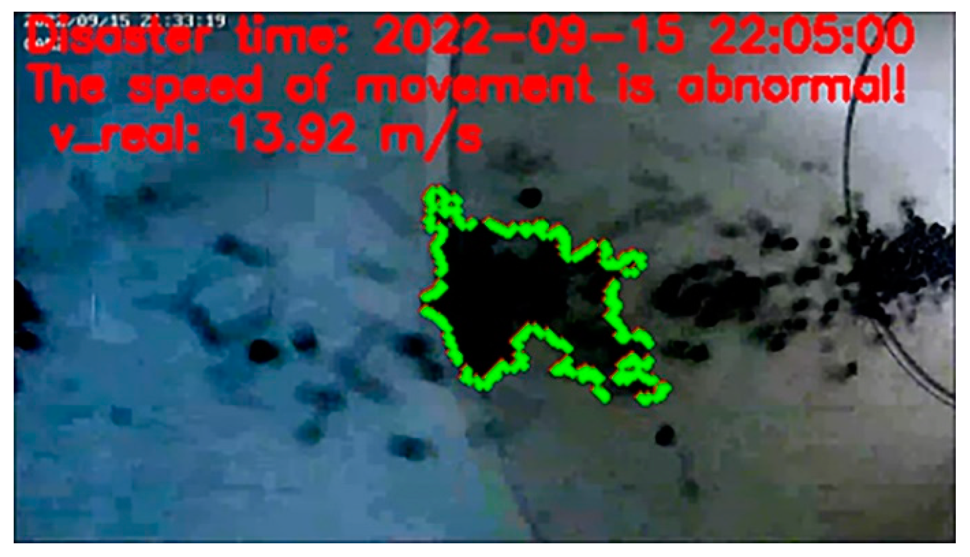
As shown in Figure 7, the color image at the moment of simulated disaster is obtained, and the area surrounded by green contours is the area of thrown coal rocks that meets the characteristics of color, brightness, and speed change at the time of disaster occurrence.
In summary, it can be seen that the disaster perception alarm method proposed in this paper can identify the features wherein the black area of the image changes significantly when a disaster occurs, the average brightness is less than the set threshold, and the object that causes the black area of the image to change significantly moves at a speed greater than the set threshold. The rock burst or coal and gas outburst perception alarm can be used based on the characteristics of an ambient methane concentration in the monitoring area of the color camera. That is, simulation experiments are used to verify the feasibility and effectiveness of the perception alarm method of coal mine rock bursts and coal and gas outbursts based on visible images proposed in this paper, and can filter the interference factors of gas and coal dust explosion, which may have high speed and abnormally high brightness, and thus reduce the false-alarm rate.
In practical engineering applications, the corresponding thresholds can be adjusted according to the actual working conditions, as well as further optimize the recognition methods of color change, average brightness, and moving speed features when disasters occur.
5. Conclusions
- (1)
- A coal mine rock burst and coal and gas outburst perception alarm method based on visible light imagery is proposed. Using the coal mine underground equipment, which has an obvious color difference from disaster-thrown coal rock, as the background, we used the large increase in the amount of black area in the color video image to capture the disaster-thrown coal rock, an average brightness that is less than the set brightness threshold to exclude the interference of gas and coal dust explosion, and the speed threshold to exclude the interference of the movement of objects in normal working conditions; moreover, the methane concentration of multiple areas must be obviously increased or reach the alarm value to further distinguish between the rock burst and coal and gas outburst;
- (2)
- A set of experimental devices for simulating the color, brightness, and speed characteristics of rock bursts and coal and gas outbursts were designed: a Φ315 mm white PVC pipe was used to simulate the circular roadway and background equipment. An axial flow high-pressure blower was used as the power device, and Φ10 mm rubber balls of similar color and specific gravity were used to replace the broken coal rocks thrown during the disaster to simulate the abnormal characteristics of speed and color caused by a large number of coal rocks thrown during a disaster. Additionally, by building a wireless cascade monitoring system, a hemispherical color camera with 2.8 mm focal length, 30 FPS, and 110° field of view was used to complete the monitoring and color video image acquisition of the simulated disaster process. The device provided a good simulation of disaster characteristics, simplified the complexity of disaster simulation experiments, and ensured experimental safety;
- (3)
- The study shows that by identifying the occurrence of simulated disasters, the disaster perception alarm method proposed in this paper can identify the situation where the image color changes significantly, the average brightness of the image is less than the set threshold, and the movement speed of the object that causes the image color to change significantly is greater than the set threshold when a disaster occurs; moreover, the disaster alarm saves the image at the moment when the threshold condition is met. This verifies the feasibility and effectiveness of the perception alarm method of coal mine rock bursts and coal and gas outbursts based on visible light imagery. The method can be adapted well to the underground scenario of coal mines to better meet the demand for the image perception of rock bursts and coal and gas outbursts, which can improve the response speed of disasters and accidents; gain valuable time for self-rescue and rescue after disasters; and reduce the risk of secondary disasters caused by gas asphyxiation and gas and coal dust explosions;
- (4)
- The method proposed in this paper can be applied not only for rock burst and coal and gas outburst disaster alarms in coal mines, but also for rock burst disaster alarms in non-coal mines. Multidimensionally, it can also be used for the early warning of serious secondary disasters such as gas asphyxiation and gas and coal dust explosions due to rock bursts and coal and gas outbursts.
Author Contributions
Conceptualization, J.C. and Y.L.; methodology, J.C.; software, J.C.; validation, J.C., Y.L. and X.L.; formal analysis, J.C.; investigation, J.C. and Y.L.; resources, J.C., Y.L. and X.L.; data curation, J.C. and X.L.; writing—original draft preparation, J.C.; writing—review and editing, J.C.; visualization, J.C.; supervision, J.C. and Y.L.; project administration, J.C., Y.L. and X.L.; funding acquisition, J.C. and Y.L. All authors have read and agreed to the published version of the manuscript.
Funding
This research was funded by the National Key Research and Development Program of China, grant number 2016YFC0801800.
Data Availability Statement
Not applicable.
Conflicts of Interest
The authors declare no conflict of interest.
References
- Sun, J. Accident Analysis and Big Data and Internet of Things in Coal Mine. Ind. Mine Autom. 2015, 41, 1–5. [Google Scholar] [CrossRef]
- Sun, J.; Qian, X. Coal Mine Accident and Emergency Rescue Technology and Equipment. Ind. Mine Autom. 2016, 42, 1–5. [Google Scholar] [CrossRef]
- Sun, J. Research on Coal-mine Safe Production Conception. J. China Coal Soc. 2011, 36, 313–316. [Google Scholar] [CrossRef]
- Sun, J. Requirement and Key Technology on Mine Informationalization and Intelligent Technology. Coal Sci. Technol. 2014, 42, 22–25+71. [Google Scholar] [CrossRef]
- Sun, J. New Technologies and New Equipment of Coal Mine Monitoring. Ind. Mine Autom. 2015, 41, 1–5. [Google Scholar] [CrossRef]
- Zheng, Y.; Zhao, Z.; Zhao, T.; Ma, C.; Zhang, K.; Qi, Y. A New Method for Monitoring Coal Stress While Drilling Process: Theoretical and Experimental Study. Energy Sources Part A-Recovery Util. Environ. Eff. 2023, 45, 3980–3993. [Google Scholar] [CrossRef]
- Liu, X.; Zhang, S.; Wang, E.; Zhang, Z.; Wang, Y.; Yang, S. Multi-Index Geophysical Monitoring and Early Warning for Rock burst in Coalmine: A Case Study. Int. J. Environ. Res. Public Health 2023, 20, 392. [Google Scholar] [CrossRef] [PubMed]
- Ji, P.; Shi, S.; Lu, Y.; He, L. Research on Risk Identification of Coal and Gas Outburst Based on PSO-CSA. Math. Probl. Eng. 2023, 2023, 5299986. [Google Scholar] [CrossRef]
- Zhang, E.; Zhou, B.; Yang, L.; Li, C.; Li, P. Experimental study on the microseismic response characteristics of coal and gas outbursts. Process Saf. Environ. Prot. 2023, 172, 1058–1071. [Google Scholar] [CrossRef]
- Wang, A.; Qiu, L.; Liu, Y.; Lou, Q.; Sun, Z.; Wang, W. Study on Synchronous Response Law of Acoustic and Electrical Signals of Outburst Coal Rock under Load and Fracture. Geofluids 2023, 2023, 1253236. [Google Scholar] [CrossRef]
- Zhou, X.; Liu, X.; Wang, X.; Liu, Y.; Xie, H.; Du, P. Acoustic Emission Characteristics of Coal Failure Under Triaxial Loading and Unloading Disturbance. Rock Mech. Rock Eng. 2023, 56, 1043–1061. [Google Scholar] [CrossRef]
- Di, Y.; Wang, E.; Li, Z.; Liu, X.; Li, B. Method for EMR and AE interference signal identification in coal rock mining based on recurrent neural networks. Earth Sci. Inform. 2021, 14, 1521–1536. [Google Scholar] [CrossRef]
- Deng, B.; Nie, B.; Liu, X.; Shi, F. Characteristics of the heterogeneous mechanical response of coal at the nano and micro-scale using instrumented indentation experiments. Chin. J. Theor. Appl. Mech. 2022, 54, 2304–2317. [Google Scholar]
- Chaolin, Z.; Enyuan, W.; Yibo, W.; Zhou, X. Development and application of multi-functional test system for coal and gas outburst simulation. Chin. J. Rock Mech. Eng. 2022, 41, 995–1007. [Google Scholar] [CrossRef]
- Yiyu, L.; Ziye, P.; Binwei, X. Multi-functional physical model testing system of deep coal petrography engineering. J. China Coal Soc. 2020, 45, 272–283. [Google Scholar] [CrossRef]
- Zhou, B.; Xu, J.; Peng, S. Dynamic evolution of gas outburst Multiphysics parameters based on visual data. J. China Univ. Min. Technol. 2020, 49, 1067–1075. [Google Scholar] [CrossRef]
- Yuan, L.; Jiang, Y.; He, X.; Dou, L.; Zhao, X.; Wang, K.; Yu, Q.; Lu, X.; Li, H. Research Progress of Precise Risk Accurate Identification and Monitoring Early Warning on Typical Dynamic Disasters in Coal Mine. J. China Coal Soc. 2018, 43, 306–318. [Google Scholar] [CrossRef]
- Qi, Q.; Li, Y.; Zhao, S.; Zhang, N.; Zheng, W.; Li, H.; Li, H. Seventy Years Development of Coal Mine Rock burst in China: Establishment and Consideration of Theory and Technology System. Coal Sci. Technol. 2019, 47, 1–40. [Google Scholar] [CrossRef]
- Jiang, Y.; Pan, Y.; Jiang, F.; Dou, L.; Ju, Y. State of the Art Review on Mechanism and Prevention of Coal Bumps in China. J. China Coal Soc. 2014, 39, 205–213. [Google Scholar] [CrossRef]
- Wang, J.; Wang, E.; Yang, W.; Li, B.; Li, Z.; Liu, X. Rock Burst Monitoring and Early Warning Under Uncertainty Based on Multi-information Fusion Approach. Measurement 2022, 205, 112188. [Google Scholar] [CrossRef]
- Zhang, X.; Tang, J.; Yu, H.; Pan, Y. Gas Pressure Evolution Characteristics of Deep True Triaxial Coal and Gas Outburst Based on Acoustic Emission Monitoring. Sci. Rep. 2022, 12, 21738. [Google Scholar] [CrossRef] [PubMed]
- Ding, Y.; Dou, L.; Cai, W.; Chen, J.; Kong, Y.; Su, Z.; Li, Z. Signal Characteristics of Coal and Rock Dynamics with Micro-seismic Monitoring Technique. Int. J. Min. Sci. Technol. 2016, 26, 683–690. [Google Scholar] [CrossRef]
- Sun, J. Alarm methods of coal and gas outburst. Ind. Mine Autom. 2014, 40, 1–5. [Google Scholar] [CrossRef]
- Sun, J.; Yu, X. Research on Alarm Method of Coal Mine Extraordinary Accidents Based on Sound Recognition. Ind. Mine Autom. 2021, 47, 1–5+44. [Google Scholar] [CrossRef]
- Sun, J.; Yu, X.; Wang, Y.; Li, X. Research on Perception Method of Coal Mine Gas and Coal Dust Explosion Based on Explosion Sound Recognition. Ind. Mine Autom. 2023, 49, 1–114. [Google Scholar] [CrossRef]
- Sun, J.; Yu, X.; Wang, Y. Recognition Method of Coal Mine Gas and Coal Dust Explosion Based on Sound Spectrogram and SVM. Coal Sci. Technol. 2023, 51, 366–376. [Google Scholar] [CrossRef]
- Sun, J.; Yu, X. Sound Recognition Method of Coal Mine Gas and Coal Dust Explosion Based on CEEMD Component Sample Entropy and SVM Classification. J. Min. Saf. Eng. 2022, 39, 1061–1070. [Google Scholar] [CrossRef]
- Sun, J.; Yu, X. Recognition Method of Coal Mine Gas and Coal Dust Explosion Based on Sound Characteristics. J. China Univ. Min. Technol. 2022, 51, 1096–1105. [Google Scholar] [CrossRef]
- Sun, J.; Cheng, J. Study on the Perception and Alarm Method of Coal Mine Rock Burst and Coal and Gas Outburst. Ind. Mine Autom. 2022, 48, 1–6. [Google Scholar] [CrossRef]
- Sun, J.; Cheng, J.; Wang, Y. Coal Mine Rock Burst and Coal and Gas Outburst Perception Alarm Method Based on Color Image. Ind. Mine Autom. 2022, 48, 1–5. [Google Scholar] [CrossRef]
- Nie, B.; Ma, Y.; Meng, J.; Hu, S. Middle Scale Simulation System of Coal and Gas Outburst. Chin. J. Rock Mech. Eng. 2018, 37, 1218–1225. [Google Scholar] [CrossRef]
- Yuan, R.; Li, H. Development and Application of Simulation Test Apparatus for Gassy Coal Dynamic Failure. J. China Coal Soc. 2013, 38, 117–123. [Google Scholar] [CrossRef]
- State Administration of Work Safety. Coal Mine Safety Regulations; Coal Industry Press: Beijing, China, 2022.
- Zhang, Y.; Wang, D.; Zhu, H. Coal Mine Explosion, Fire and Its Prevention Technology; China University of Mining and Technology Press: Xuzhou, China, 2007. [Google Scholar]
- AQ1029-2019; Specification for the Use and Management of Coal Mine Safety Monitoring Systems and Detection Instruments. Emergency Management Press: Beijing, China, 2019.
- Wang, X.; Han, J.; Xiang, H.; Wang, B.; Wang, G.; Shi, H.; Chen, L.; Wang, Q. A Lightweight Traffic Lights Detection and Recognition Method for Mobile Platform. Drones 2023, 7, 293. [Google Scholar] [CrossRef]
- Ma, H.; Liu, Z.; Jiang, K.; Jiang, B.; Feng, H.; Hu, S. A Novel ST-ViBe Algorithm for Satellite Fog Detection at Dawn and Dusk. Remote Sens. 2023, 15, 2331. [Google Scholar] [CrossRef]
Figure 1.
Color characteristics of typical equipment in coal mine: (a) roadheader (orange), (b) dust blower (white), (c) workbench (blue), (d) hydraulic support column (silver), (e) explosion-proof water bag (orange-red), and (f) mobile substation (blue, red).
Figure 1.
Color characteristics of typical equipment in coal mine: (a) roadheader (orange), (b) dust blower (white), (c) workbench (blue), (d) hydraulic support column (silver), (e) explosion-proof water bag (orange-red), and (f) mobile substation (blue, red).
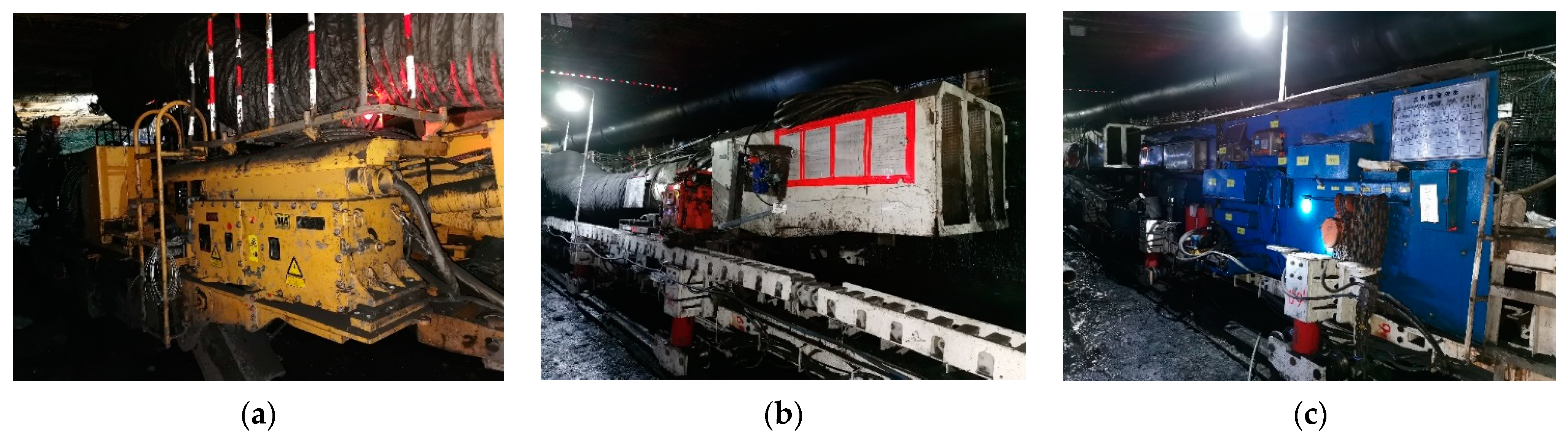
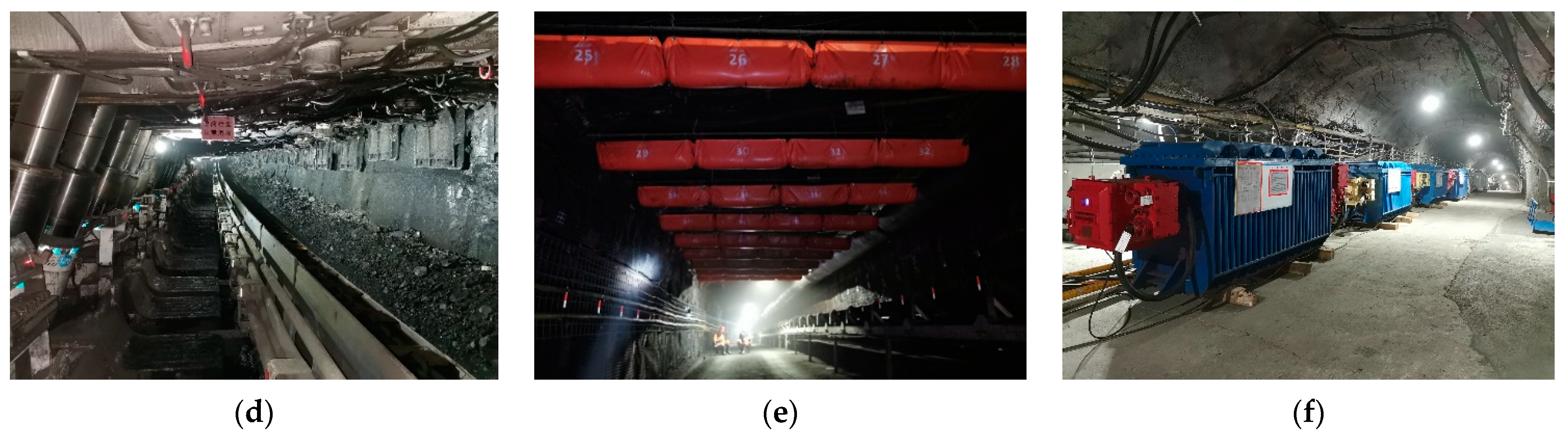
Figure 2.
The coal mine rock burst and coal and gas outburst perception alarm method based on visible light imagery.
Figure 2.
The coal mine rock burst and coal and gas outburst perception alarm method based on visible light imagery.
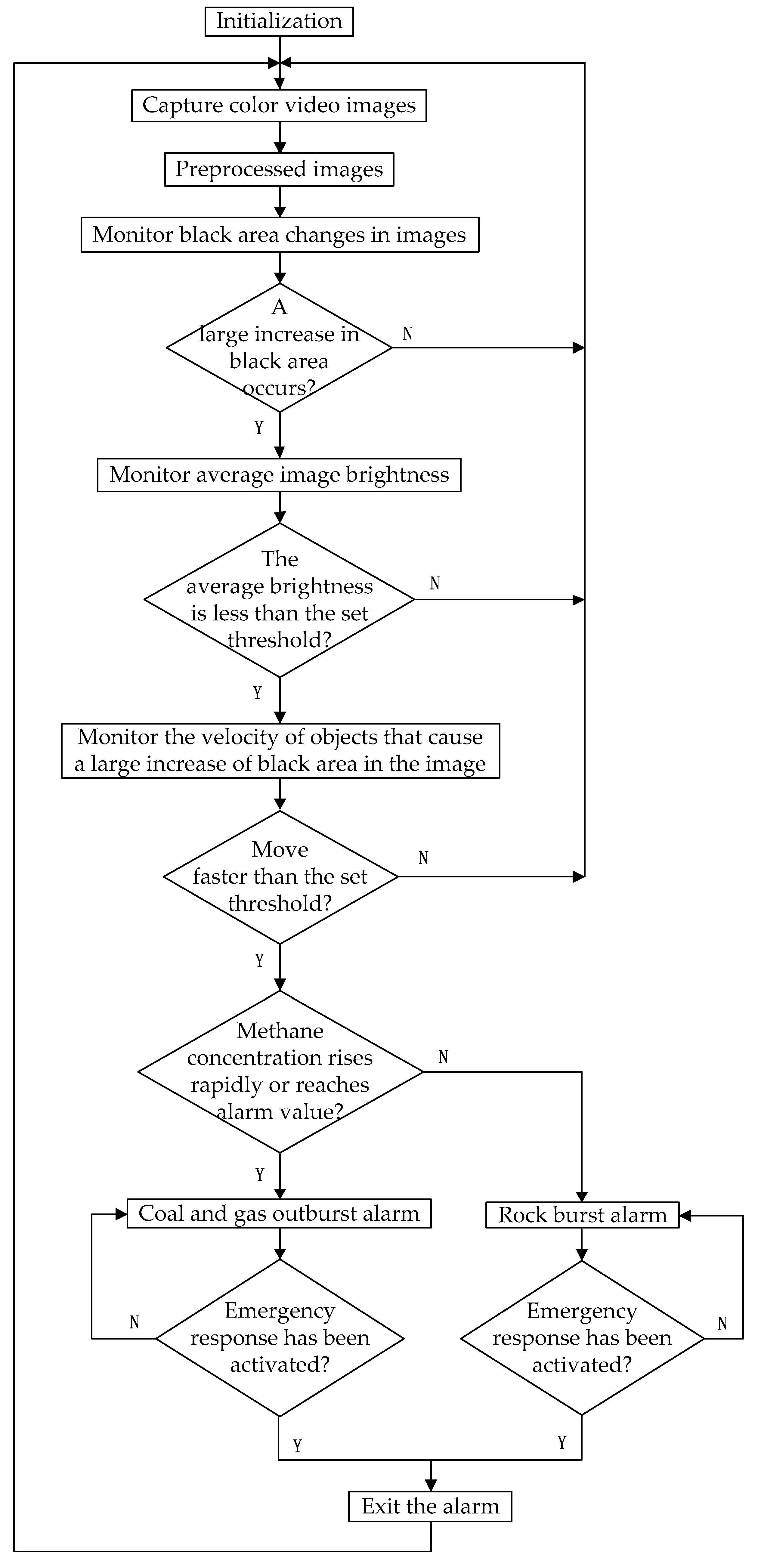
Figure 3.
Color camera in the tilt angle of the speed measurement method schematic.

Figure 4.
Overall schematic diagram of the experimental scheme.
Figure 5.
Overall diagram of the simulation experiment.
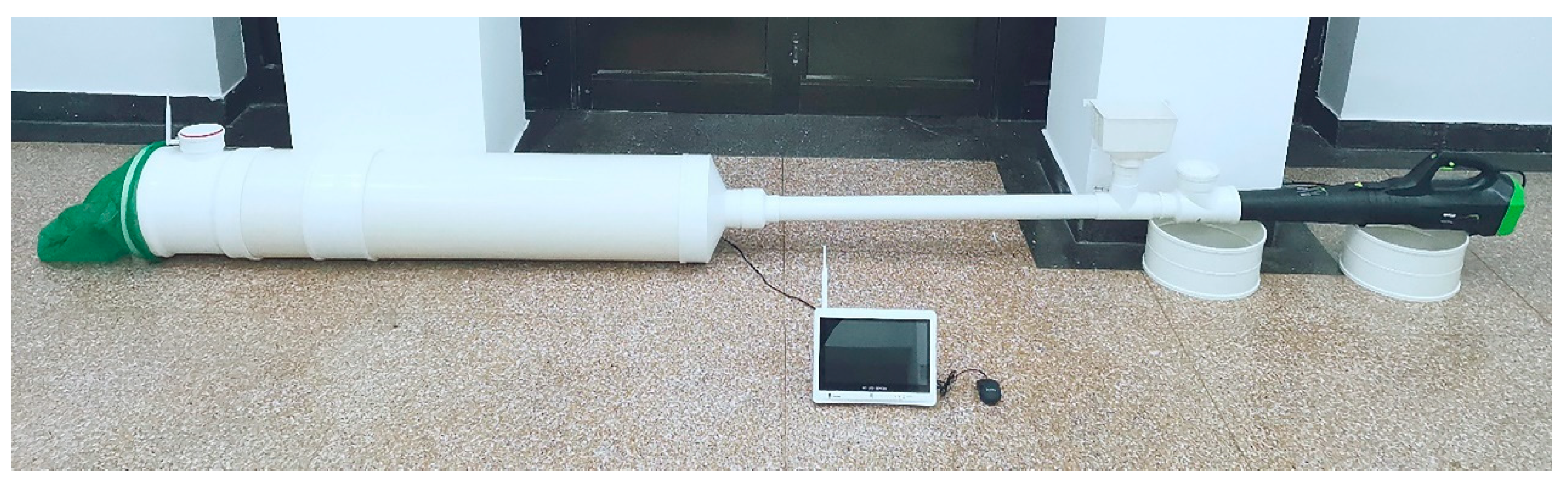
Figure 6.
Simulation of coal rocks thrown during disaster. (a) Before the disaster; (b) early stages of the disaster; (c) mid-disaster period; (d) later stages of the disaster.
Figure 6.
Simulation of coal rocks thrown during disaster. (a) Before the disaster; (b) early stages of the disaster; (c) mid-disaster period; (d) later stages of the disaster.
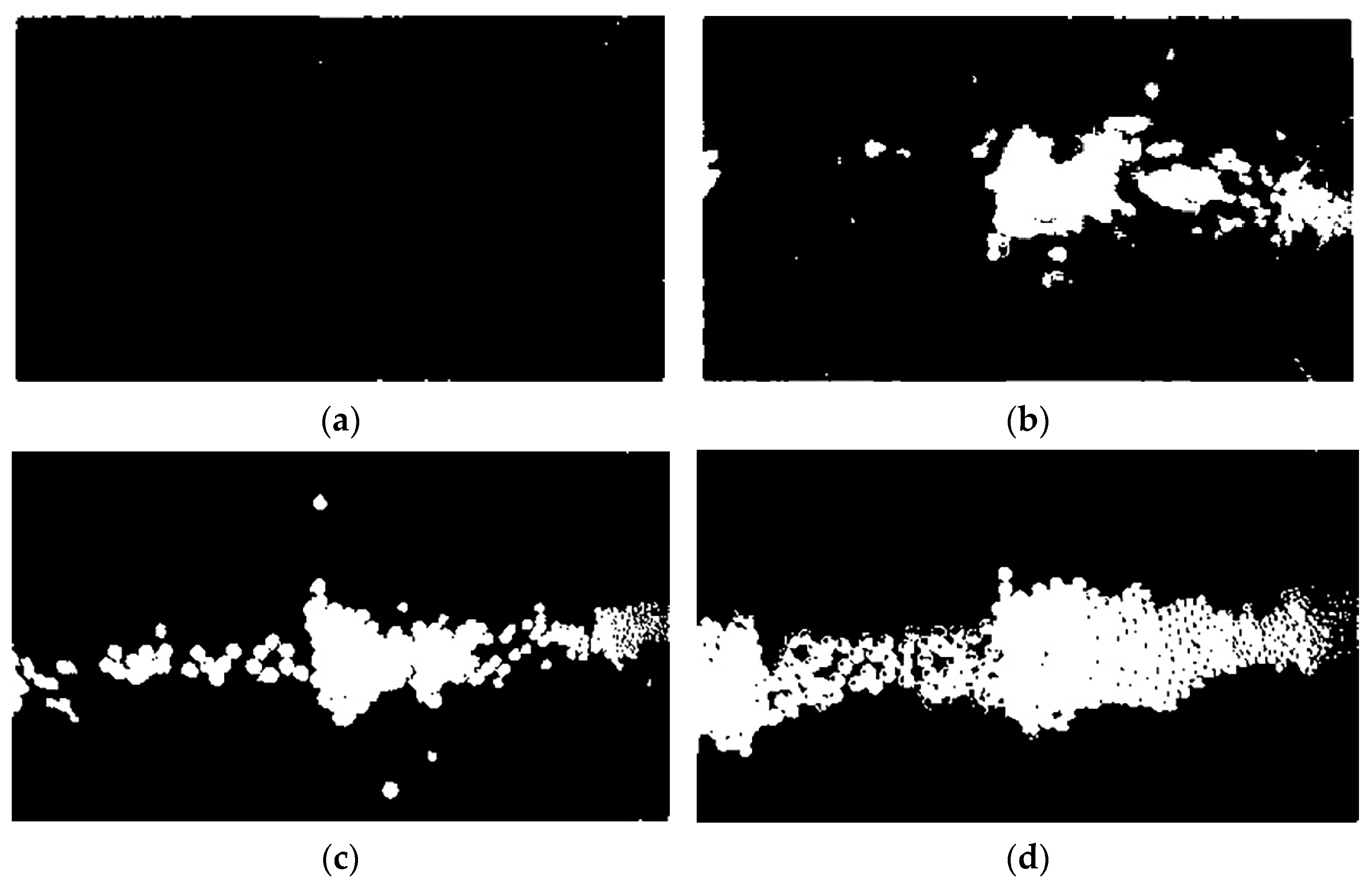
Figure 7.
Thrown coal rock velocity exceeds the set threshold.
Disclaimer/Publisher’s Note: The statements, opinions and data contained in all publications are solely those of the individual author(s) and contributor(s) and not of MDPI and/or the editor(s). MDPI and/or the editor(s) disclaim responsibility for any injury to people or property resulting from any ideas, methods, instructions or products referred to in the content. |
© 2023 by the authors. Licensee MDPI, Basel, Switzerland. This article is an open access article distributed under the terms and conditions of the Creative Commons Attribution (CC BY) license (https://creativecommons.org/licenses/by/4.0/).
Share and Cite
MDPI and ACS Style
Cheng, J.; Liu, Y.; Li, X. Coal Mine Rock Burst and Coal and Gas Outburst Perception Alarm Method Based on Visible Light Imagery. Sustainability 2023, 15, 13419. https://doi.org/10.3390/su151813419
AMA Style
Cheng J, Liu Y, Li X. Coal Mine Rock Burst and Coal and Gas Outburst Perception Alarm Method Based on Visible Light Imagery. Sustainability. 2023; 15(18):13419. https://doi.org/10.3390/su151813419
Chicago/Turabian StyleCheng, Jijie, Yi Liu, and Xiaowei Li. 2023. "Coal Mine Rock Burst and Coal and Gas Outburst Perception Alarm Method Based on Visible Light Imagery" Sustainability 15, no. 18: 13419. https://doi.org/10.3390/su151813419
Note that from the first issue of 2016, this journal uses article numbers instead of page numbers. See further details here.