
A New Dual Stator Permanent Magnet Machine Based on Field Modulation Theory
Jiangsu Provincial Key Laboratory of 3D Printing Equipment and Manufacturin, NARI School of Electrical and Automation Engineering, Nanjing Normal University, Nanjing 210023, China
*
Author to whom correspondence should be addressed.
Sustainability 2023, 15(1), 281; https://doi.org/10.3390/su15010281
Submission received: 18 October 2022
/
Revised: 20 December 2022
/
Accepted: 21 December 2022
/
Published: 24 December 2022
(This article belongs to the Special Issue Intelligence and Sustainability in Electrical Engineering)
Abstract
:Increasing industrial development puts forward high requirements for the performances of stator permanent magnet (PM) machines, such as torque density and efficiency. The paper proposes a new dual stator PM machine based on field modulation theory (DSPMM), which employs the intermediate rotor participating in the electromechanical energy conversion of the internal and external machine. The proposed machine has the advantages of high torque density and high efficiency and solves the problem of insufficient space utilization of a single stator machine. The evolution process and working principle of the proposed DSPMM are studied. The flux-switching-type PM (FSPM) and the flux-reversal-type PM (FRPM) are employed in the proposed DSPMM, which forms four representative machines. For a fair comparison, the proposed machines employ identical key parameters, i.e., PM volume, the outer radius of the outer stator, and active airgap length. Based on finite element analysis (FEA), the electromagnetic performances of the four representative DSPMM under no-load and rated load, and different copper consumption conditions are analyzed and compared. The calculated results show that the proposed DSPMM with inner FSPM stator and outer FRPM stator can provide high output torque, low torque ripple, high power factor, and high efficiency.
1. Introduction
The permanent magnet (PM) machine has higher efficiency and higher power density compared with traditional induction machines; it has achieved lightweight and simplicity at the same time because of the compact structure. So it is developing rapidly and is expected to replace traditional induction machines in various fields of aerospace, transportation, and industrial and agricultural production [1,2]. Currently, many PM machine drive systems use a combination of high-speed machines and mechanical gears to increase the torque density of the drive system. However, the combination leads to some issues, such as poor dynamic performance, high vibration, high noise, and low reliability [3]. To solve this problem, a machine operating based on field modulation theory (FMM) has been proposed [4,5,6]. In FMM, the high-speed armature magnetic field can be modulated into a low-speed space harmonic field and coupled with the low-speed rotating magnetic field excited by the rotor PM to produce high output torque [7,8,9,10,11]. Thus, FMM has the characteristics of high torque at low speed, which can increase torque density effectively [12,13,14]. Flux switching machines (FSMs) and flux reversing machines (FRMs) are two kinds of stator-PM FMMs, which have the advantages of simple rotor structure, high mechanical strength, and low moment of inertia [15,16,17,18,19,20]. However, the space utilization of each of the FSMs and FRMs is low, which restricts the increase of machine torque density. To solve this problem, a dual stator (DS) structure is combined with FMMs with FSMPM and FRMPM, which allows the intermediate rotor to participate in the electromechanical energy conversion of both the inner and outer machines [21,22,23]. Compared to single stator FMMs, DS FMMs offer high output torque capability, high system integration, high overload capability, and flexible operation modes with the same amount of PM volume. A dual-stator switched flux consequent pole PMM with unequal length teeth is proposed, which can significantly enhance the torque density and has good flux-regulating capability with field winding [24]. However, a single field modulation link and two airgaps in the main magnetic circuit cause high magnetic reluctance, which limits further torque production improvement. A novel dual-stator flux switching PMM is proposed, which eliminates even-order harmonics in the flux linkage and back-electromotive force which exist in the conventional single-stator single-rotor topology [25]. However, the structure of the machine is complex, and the output torque is low. A double-stator flux-switching PM machine using ferrite is proposed, which can achieve high efficiency and power density without magnetic saturation risk because of the employment of ferrite [26]. However, the existing DS FMMs usually use the same PM type in the inner and outer stators, which can not achieve the best electromagnetic performances because the PM excitations on dual stators will consume each other and can not be used effectively.
In this paper, a new dual stator PM machine based on field modulation theory (DSPMM) is proposed, which employs the flux-switching-type PM (FSPM) and the flux-reversal-type PM (FRPM) on inner and outer stators as stator-PM excitation. In addition, a common salient rotor is sandwiched between the inner and outer stators and composed of silicon iron. Therefore, the proposed machine has the merits of high space utilization, high output torque, and high efficiency. The evolution process from the conventional FSM and FRM to the proposed machine and the operating principle of the DSPMM are provided. Then, the DSPMM with FSPM on the outer stator and FRPM on the inner stator is proposed. Two conventional DSPMMs with FRPM and FSPM on both the inner and outer stators are designed as well. The electromagnetic performances of these four representative machines are analyzed based on finite element analysis (FEA) under no load, rated load, and different copper consumption conditions and compared for some beneficial conclusions.
This paper will be organized as follows: Section 2 provides the design principles and the evolution process for the new machine, together with design considerations. Then, in Section 3, the electromagnetic performances of the proposed machines and the conventional machines are analyzed and compared using FEA. In Section 4, some beneficial conclusions are presented.
2. Topology and Operating Principle
2.1. Topology
Figure 1 shows the evolution process of the proposed DSPMM with an inner FSPM stator and outer FRPM stator from the conventional FSM and FRM. In FSM, the circumferential magnetization PMs are inserted in the center of stator teeth, in which the adjacent PMs have opposite polarity. Compared to FSM, FRM employs the two adjacent radial magnetization PMs with opposite polarity mounted on the tops of the stator teeth to build the main flux paths. For both FSM and FRM, the salient rotor is used to force the magnetic field to rotate. The proposed machines adopt the fractional slot concentrated windings which are wounded around the stator teeth. It has the advantages of the short end and low copper, which is conducive to reducing the temperature rise at the rated state and improving efficiency. The relationship between the number of rotor teeth and the pole pair numbers (PPNs) of stator-PM and armature reaction follows the field modulation theory.
In Figure 1, FSM with an outer salient rotor and FRM with an inner salient rotor are presented. When the outer radius of the salient rotor in FSM shares the same value as the inner radius of the salient rotor in FRM, these two machines can be combined. Then, a new proposed DSPMM with an inner FSPM stator and outer FRPM stator can be obtained and is simply referred to as Model A, whose combination process is shown in Figure 1. The combination process of the proposed DSPMM with inner FRPM stator and outer FSPM is shown in Figure 1b, in which the proposed machine is simply referred to as Model B. Because the proposed machines operate based on flux modulation effect and contain dual PM excitation and dual stator, the proposed topologies are designed based on the design principle of the machines using multiple layers of PM excitations and modulators in [27]. The proposed machines can be classified into the R-S-R-S-R structure, in which the R and S represent the rotating and stationary parts, respectively.
As a consequence, DSPMMs with FSPM and FRPM on both the inner and outer stators can be obtained, which are simply referred to as Model C and Model D, respectively. Then, these four representative machines are shown in Figure 2, which share identical key design parameters, such as the amount of PMs and the PPN of the modulation pole.
2.2. Operating Principle
According to the characteristics of the geometrical configuration shown in Figure 2, the proposed DSPMMs can be separated into two sections, i.e., Model A can be considered as one outer FRM and one inner FSM. Therefore, the theoretical analysis of the proposed machines can be regarded as two separate machines for analysis.
The PMs on inner and outer stators are used to provide a magnetomotive force (MMF). Using fast Fourier decomposition, the MMF expressions of PMs on the inner stator (Fi) and PM on the outer stator (Fo) are:
where Foj and Fij are the Fourier coefficients of magnetic motive force (MMF), respectively. Pie and Poe are the PPNs of MMF excited by PMs on inner and outer stators, respectively. θs is the position of the PMs on stators. o and i in the variables represent the inner and outer stators, respectively.
The flux densities in inner and outer airgaps are modulated by salient rotor teeth; the field modulation effect can be expressed by the permeance function. The permeance function ignoring the high-order harmonics can be expressed as follows
where Λo0 and Λo1 are the Fourier coefficient of the outer stator permeance function, respectively. Λi0 and Λi1 are the Fourier coefficient of the inner stator permeance function, respectively.; Pf is the fundamental harmonic component PPN of airgap permeance.
The relationships of PPNs of armature reaction, MMF excited by stator PMs and the fundamental harmonic component PPN of airgap permeance should satisfy
Based on the magnetic circuit principle, the no-load air gap magnetic density distribution of outer and inner airgaps can be expressed as follows
The winding function of the stator winding can be expressed as
where Nw is the Number of turns of armature winding; θio is the angle between the center line of inner and outer stator teeth.
According to the winding function theory and Faraday law of electromagnetic induction, the no-load back electromotive force (back-EMF) of the machine can be expressed as
where kw Rso, Rsi, and La are the armature winding coefficient, inner diameter of outer stator, outer diameter of inner stator, and axial length of motor, respectively.
The inner and outer stator coils are connected, so the back-EMF of the proposed machines can be expressed as
Then, the comparisons of analytical and FEA-calculated results are shown in Figure 3, including airgap flux density and back-EMFs of models A and B. It can be seen that the analytical and FEA-calculated results have a good agreement. The analytical results agree well with the FEA-calculated results, with a slight difference caused by ignoring flux leakage.
2.3. Key Parameters Design
In order to achieve the objectives of high torque output, low torque ripple, and high efficiency, the key parameters of the rotor of the proposed machines need to be optimized; the definitions of two key parameters shown in Figure 4 HR indicate the thickness of the machine rotor yoke, and θT is the misalignment angle between the inner and outer teeth of the rotor.
Figure 5 gives the variation of average torque to HR for these four representative machines when θT is 0. It can be seen that the average torques of Model A and Model B are higher than those of Model C and Model D at various HR. It indicates that the proposed DSPMM with different types of PM excitation can offer high output torque and use an effective magnetic field to realize electromechanical energy conversion. The maximum average torque can be achieved in Model C and Model D when the rotor yoke thickness HR is 0 mm because the magnetic field excited by the inner and outer PM stators will be weakened for each other in the rotor yoke when the inner and outer stator employ the same stator PM type. For Model A and Model B, the maximum average torque can be obtained when the rotor yoke thickness HR is 5 mm. It indicates that the PM excitation excited by different stator PM types in two stators is useful for each other.
Figure 6 gives the variation of average torque to θT, when HR is the value that these four investigated machines can obtain the maximum average torque at the value. It can be seen that the average torque varies almost sinusoidally with θT, with 2.61 Nm at θT = 7 deg of Model A, 2.22 Nm at θT = 2 deg of Model B, 1.84 Nm at θT = 10 deg of Model C and 0.78 Nm at θT = 18 deg of Model D. The maximum average torque of these models can be reached at different θT, therefore, θT has a great influence on the airgap flux density distribution and average torque. The main reason is that the salient rotor teeth act the role of modulation to modulate the inner and outer airgap flux density. Based on the design considerations mentioned, Table 1 lists the design parameters of the proposed models.
3. Electromagnetic Performance Analysis
For a fair comparison, these four models share the same key design parameters, i.e., stack length, the outer radius of inner and outer stators, the inner and outer air-gap lengths, and PM volume. The electromagnetic performances under no-load, rated load, and different copper consumption conditions are analyzed using FEA.
3.1. No-Load Airgap Flux Density
The outer airgap flux densities and their corresponding harmonics analysis of these four investigated models at no load state is given in Figure 7. The outer stator of Model B and Model C employ 6-PPN of FSPM excitation, 12-slot/10-pole fractional concentrated armature windings, and 11-number of rotor teeth. According to the field modulation theory, it can be calculated that the fifth, sixth, and seventh harmonic components are working harmonics in the outer airgap of Model B and Model C. From Figure 7b, the FEA-calculated results of the harmonic spectra agree with the theoretical analysis. The fifth and the sixth working harmonic components of Model C are lower than those of Model B, and the total harmonic distortion (THD) of Model B is lower than that of Model C. Therefore, it can be known that Model B provides high output torque and low torque ripple when compared to Model C. The main reason is that Model B employs different stator PM types on the inner and outer stators.
The outer stator of Model A and Model D employ 12-PPN of FRPM excitation, 12-slot/2-pole fractional concentrated armature windings, and 11-number of rotor teeth. It should be noted that the PPNs of FSPM and FRPM in the 12-slot stator are different. The working harmonic orders of Model A and Model D are the 1st and 12th, which can be calculated based on the field modulation theory and match the FEA-calculated results. It also can be seen that the 12th harmonic component of Model A is much higher than that of Model D because Model A employs different stator PM types on the inner and outer stators, which agrees with the analysis of the outer airgap flux density of Model B and Model C.
Figure 8 shows the inner airgap flux densities and their corresponding harmonics analysis of these four investigated models at no load state. As the proposed DSPMMs can be considered as two separate machines for theoretical analysis, the working harmonic orders in airgaps facing the stator using the same stator PM type are equal. Model A and Model C share the same FRPM on the inner stator, whose working harmonic orders are the fifth, the sixth, and the seventh. In addition, the 1st and 12th harmonics are the working harmonic components for torque production. The FEA-calculated results in Figure 8b show that the investigated models using different stator PM types on the inner and outer stators have high amplitudes of working harmonic components.
3.2. No-Load Magnetic Field Distribution
Figure 9 presents the Magnetic field distribution of these four models at no load state, which is a combination of the flux lines and magnetic density distribution. The maximum flux density of all of these four models is 2.0 T, which is below the magnetic saturation threshold of silicon steel. The flux densities of Model B and Model C are higher when compared to Model D because, in Model D, the stator PMs in the inner and outer stators consume each other rather than participate in electromechanical energy conversion. In addition, the flux density in the stator yoke is low due to its large size, but high flux density appears at the junction of PM and silicon steel and the top of stator teeth. It should be noted that these four models have no magnetic saturation risk.
3.3. No-Load Back-EMF
Figure 10 gives the back-EMF waveforms and the corresponding harmonic spectra for these four investigated models under no-load conditions. It can be seen that the back-EMF fundamental amplitudes of Model A and Model B are higher than those of Model C and Model D. It indicates that the back-EMF amplitude is high when different stator PM types are used for the inner and outer stators of the proposed machine, which agrees with the airgap flux density analysis. The back-EMF fundamental amplitude of Model A is 2.8 V higher than that of Model B, and the third harmonic amplitude is lower than that of Model B. Therefore, Model A should have higher steady torque and lower torque ripple than Model B. It can be known that the proposed DSPMM with inner FSPM stator and outer FRPM stator can offer high back-EMF and low harmonic distortion.
3.4. Torque Characteristics
Figure 11 shows the cogging torque and steady torque at the rated state of these four machines. From Figure 11a, the peak-to-peak values of cogging torque of these four models are low because the greatest common divisor between stator PM and armature reaction PPNs of each model is 1 (GCD (pr, pa) = 1), which takes advantage of low cogging torque. Model D uses FRPM on the inner and outer stators and has the lowest peak-to-peak values of cogging torque. In addition, Model A performs lower cogging torque when compared to Model B and Model C, which means that the outer stator using FRPM can decrease the cogging torque. In Figure 11b, the steady torque waveforms of these four models can be obtained when the rated current (1.7 Arms) is applied. The average values of steady torque of the machines using the different stator PM types are higher than those of the machines employing the same stator PM type in the inner and outer stators. It can be seen that Model A can provide the highest steady torque (2.60 Nm) and the lowest torque ripple (3.47%) at the rated state.
Figure 12 shows the average value of steady torque versus current angle for these four models when the rated current is applied. The maximum steady torque of each model can be obtained when the current angle is 0°. Therefore, in these four models, Id = 0 control can be used in the constant-torque region. Furthermore, at different current angles, the average values of steady torque of Model A and Model B are high.
The steady torques and torque ripples against copper loss for these four models are shown in Figure 13, in which the average values of steady torques at the rated state are marked with dashed lines. From Figure 13a, Model A provides the highest steady torques at different copper losses when compared to the other three models. In addition, the torque ripple of Model A is the lowest among the investigated models. Therefore, Model A, the proposed DSPMM with inner FSPM stator and outer FRPM stator, is desirable because of high output torque and low torque ripple. Model D offers the worst quality output torque among these models. The discussion about steady torques and torque ripples against copper loss for these four models agrees with the performance analysis at a no-load state.
3.5. Power Factor and Efficiency
Figure 14 shows the power factor and efficiency against copper loss for these four models, in which the power factor and efficiency at the rated state are marked with dashed lines.
The power factor can be defined as
where E0 is the phase induced voltage at no-load state; Xq and Iq donate the q-axis synchronous inductance and the q-axis current, respectively.
From Figure 14a, the power factor of Model A and Model B is higher than 0.9, which is also higher than 0.75 for Model C and 0.67 for Model D. The proposed models can be regarded as two separated FSM or FRM; then, these models composed of the same stator PM type, Model C and Model D, suffer the inherent issue of lower power factor. Another reason is that in Model C and Model D, the PM excitations on dual stators will consume each other. Compared to Model C and Model D, PM excitation in Model A and Model B can be used effectively in electromechanical energy conversion. It also can verify that the employment of the DS structure can increase power effectively [28,29,30].
Machine efficiency can be defined as
where Poutput, Pcopper, Piron, and Pmagnet refer to the output power, the copper loss, the iron loss, and the magnetic loss, respectively.
From Figure 14b, the curves of efficiency against copper loss follow the same trend because they share the same key design parameters. With the copper loss rising, the iron core and PM loss increase, which is the main reason that the efficiencies of these four models decrease with copper loss increasing. It can be seen that Model B has the highest efficiency at a different copper loss, though the average values of steady torque of Model B are a little lower than those of Model A. Therefore, the investigated losses of Model B are lower than the other three models.
In order to show the merits of these models, the electromagnetic performances of these models under no-load and rated states are analyzed and listed in Table 2. The comparison shows that the proposed DSPMM using different stator PM types on the inner and outer stators have the merits of high out torque, high power factor, low torque ripple, and high efficiency.
4. Conclusions
A new DSPMM is proposed, in which the inner and outer stators use FSPM and FRPM, respectively. The evolution process, working principle, and design consideration of the proposed machine are provided. Then, the DSPMM with inner FRPM stator and outer FSPM stator is designed, together with DSPMM with the same stator PM type on the inner and outer stator. These proposed machines are working based on field modulation theory, which has the merit of high output torque at low speed. Some important conclusions are obtained in the process of the proposed machine analysis:
(1) The calculated results show that the misalignment angle between the inner and outer teeth of the rotor can decide the initial rotor position; therefore, it has a great influence on the output torque capability.
(2) The magnetic field excited by the inner and outer PM stators will be weakened for each other in the rotor yoke when the inner and outer stators employ the same stator PM type. Therefore, the proposed machines use the same stator PM type in the stator.
(3) The PM excitation excited by different stator PM types in two stators is useful for each other. Therefore, the proposed machines using different stator PM types can use PM excitation effectively, which also can exhibit a high power factor compared to those using the same stator PM type in the stators.
The analytical analysis and FEA-predicted results show that DSPMM with inner FSPM stator and outer FRPM stator has the merits the high output torque, high power factor, low cogging torque, and low torque ripple, which is the desirable choice for the electric vehicle application.
Author Contributions
Investigation, Z.D., C.H. and C.F.; Resources, J.Y. All authors have read and agreed to the published version of the manuscript.
Funding
This research was funded by National Natural Science Foundation of China grant number 51407095.
Institutional Review Board Statement
Not applicable.
Informed Consent Statement
Not applicable.
Data Availability Statement
Not applicable.
Conflicts of Interest
The authors declare no conflict of interest.
References
- Zhu, Z.Q.; Howe, D. Electrical machines and drives for electric, hybrid and fuel cell vehicles. Proc. IEEE 2007, 95, 746–765. [Google Scholar] [CrossRef]
- Chau, K.T.; Chan, C.C.; Liu, C. Overview of permanent-magnet brushless drives for electric and hybrid electric vehicles. IEEE Trans. Ind. Electron. 2008, 55, 2246–2257. [Google Scholar] [CrossRef] [Green Version]
- Boldea, I.; Tutelea, L.; Parsa, L.; Dorrell, D. Automotive electric propulsion systems with reduced or no permanent magnets: An overview. IEEE Trans. Ind. Electron. 2014, 61, 5696–5711. [Google Scholar] [CrossRef]
- Li, D.; Zou, T.; Qu, R.; Jiang, D. Analysis of fractional-slot concentrated winding PM vernier machines with regular open-slot stators. IEEE Trans. Ind. Appl. 2018, 54, 1320–1330. [Google Scholar] [CrossRef]
- Kim, B.; Lipo, T.A. Analysis of a PM vernier motor with spoke structure. IEEE Trans. Ind. Appl. 2016, 52, 217–225. [Google Scholar] [CrossRef]
- Li, X.; Chau, K.T.; Cheng, M. Comparative analysis and experimental verification of an effective permanent-magnet vernier machine. IEEE Trans. Magn. 2015, 51, 1–9. [Google Scholar]
- Zhu, X.; Lee, C.H.T.; Chan, C.C. Overview of flux-modulation machines based on flux-modulation principle: Topology, theory, and development prospects. IEEE Trans. Transp. Electrif. 2020, 6, 612–624. [Google Scholar] [CrossRef]
- Cheng, M.; Han, P.; Hua, W. General airgap field modulation theory for electrical machines. IEEE Trans. Ind. Electron. 2017, 64, 6063–6074. [Google Scholar] [CrossRef]
- Kwon, J.; Kwon, B. Investigation of dual-stator spoke-type vernier machine for EV application. IEEE Trans. Magn. 2018, 54, 1–5. [Google Scholar] [CrossRef]
- Jia, S.; Qu, R.; Li, J.; Li, D.; Kong, W. A stator-PM consequent-pole vernier machine with hybrid excitation and DC-biased sinusoidal current. IEEE Trans. Magn. 2017, 53, 1–5. [Google Scholar] [CrossRef]
- Zhang, H.; Kou, B.; Zhu, Z.Q.; Qu, R.; Luo, J.; Shao, Y. Thrust ripple analysis on toroidal-winding linear permanent magnet vernier machine. IEEE Trans. Ind. Electron. 2018, 65, 9853–9862. [Google Scholar] [CrossRef]
- Wang, H.; Fang, S.; Jahns, T.M.; Yang, H.; Lin, H. Design and analysis of a dual-rotor field modulation machine with triple PM excitation. In Proceedings of the 2018 IEEE Energy Conversion Congress and Exposition, Portland, OR, USA, 23–27 September 2018; pp. 3302–3309. [Google Scholar]
- Fang, H.; Wei, Y.; Song, R. Design and analysis of superconducting magnetic-field-modulation electric machine. IEEE Trans. Appl. Supercond. 2021, 31, 1–4. [Google Scholar] [CrossRef]
- Wang, H.; Fang, S.; Yang, H.; Lin, H.; Wang, D.; Li, Y.; Jiu, C. A novel consequent-pole hybrid excited vernier machine. IEEE Trans. Magn. 2017, 53, 1–5. [Google Scholar] [CrossRef]
- Yang, H.; Lin, H.; Zhu, Z.Q.; Lyu, S.; Liu, Y. Design and analysis of novel asymmetric-stator-pole flux reversal PM machine. IEEE Trans. Ind. Electron. 2020, 67, 101–114. [Google Scholar] [CrossRef] [Green Version]
- Tan, Q.; Wang, M.; Li, L. Analysis of a new flux switching permanent magnet linear machine. IEEE Trans. Magn. 2021, 57, 1–5. [Google Scholar] [CrossRef]
- More, D.S.; Fernandes, B.G. Analysis of flux-reversal machine based on fictitious electrical gear. IEEE Trans. Energy Convers. 2010, 25, 940–947. [Google Scholar] [CrossRef]
- Jin, M.J.; Wang, Y.; Shen, J.X. Cogging torque suppression in a permanent magnet flux-switching integrated-starter-generator. IET Electr. Power Appl. 2010, 4, 647–656. [Google Scholar] [CrossRef] [Green Version]
- Zhu, X.; Hua, W. Stator-slot/rotor-pole pair combinations of flux-reversal permanent magnet machine. IEEE Trans. Ind. Electron. 2019, 66, 6799–6810. [Google Scholar] [CrossRef]
- Hua, H.; Zhu, Z.Q. Novel hybrid-excited switched-flux machine having separate field winding stator. IEEE Trans. Magn. 2016, 52, 1–5. [Google Scholar] [CrossRef]
- Baloch, N.; Kwon, B.; Gao, Y. Low-cost high-torque-density dual-stator consequent-pole permanent magnet vernier machine. IEEE Trans. Magn. 2018, 54, 1–5. [Google Scholar] [CrossRef]
- Shi, Y.; Ching, T.W. Power factor analysis of dual-stator permanent magnet vernier motor with consideration on turn-number assignment of inner and outer stator windings. IEEE Trans. Magn. 2021, 57, 1–5. [Google Scholar] [CrossRef]
- Bilal, M.; Ikram, J. Performance improvement of dual stator axial flux spoke type permanent magnet vernier machine. IEEE Access 2021, 9, 64179–64188. [Google Scholar] [CrossRef]
- Wei, L.; Nakamura, T. Optimization design of a dual-stator switched flux consequent pole permanent magnet machine with unequal length teeth. IEEE Trans. Magn. 2020, 56, 1–5. [Google Scholar] [CrossRef]
- Li, Y.; Bobba, D.; Sarlioglu, B. Design and performance characterization of a novel low-pole dual-stator flux-switching permanent magnet machine for traction application. IEEE Trans. Ind. Appl. 2016, 52, 4304–4314. [Google Scholar] [CrossRef]
- Kim, D.; Hwang, H.; Bae, S. Analysis and design of a double-stator flux-switching permanent magnet machine using ferrite magnet in hybrid electric vehicles. IEEE Trans. Magn. 2016, 52, 1–4. [Google Scholar] [CrossRef]
- Wang, H.; Fang, S. Design of new dual-stator field modulation machines. IEEE Trans. Ind. Electron. 2020, 67, 5626–5636. [Google Scholar] [CrossRef]
- Asgar, M.; Afjei, E.; Torkaman, H. A new strategy for design and analysis of a double-stator switched reluctance motor: Electro-magnetics, FEM, and experiment. IEEE Trans. Magn. 2015, 51, 1–8. [Google Scholar] [CrossRef]
- Chai, F.; Pei, Y.; Zheng, P. Analysis and restrain strategy of cogging torque in double-stator permanent magnet brushless motor. In Proceedings of the IEEE International Electric Machines and Drives Conference, Madison, WI, USA, 1–4 June 2003; Volume 2, pp. 1073–1077. [Google Scholar]
- Chai, F.; Xia, J.; Guo, B. Double-stator permanent magnet synchronous in-wheel motor for hybrid electric drive system. IEEE Trans. Magn. 2009, 45, 278–281. [Google Scholar] [CrossRef]
Figure 1.
Evolution process of the proposed DSPMM from the conventional FSM and FRM.
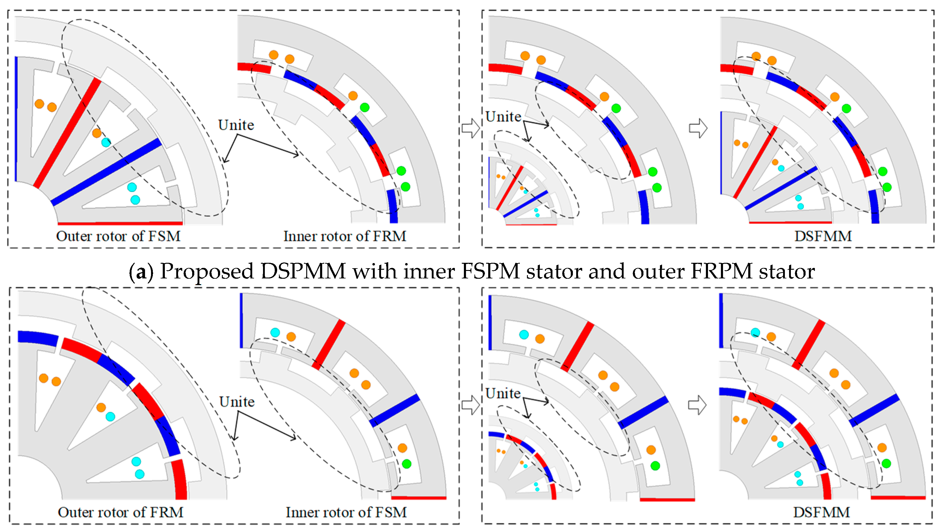
Figure 2.
Four representative DSPMMs.

Figure 3.
The comparison of analytical and FEA-calculated results of airgap flux density and back-EMF of Models A and B.
Figure 3.
The comparison of analytical and FEA-calculated results of airgap flux density and back-EMF of Models A and B.
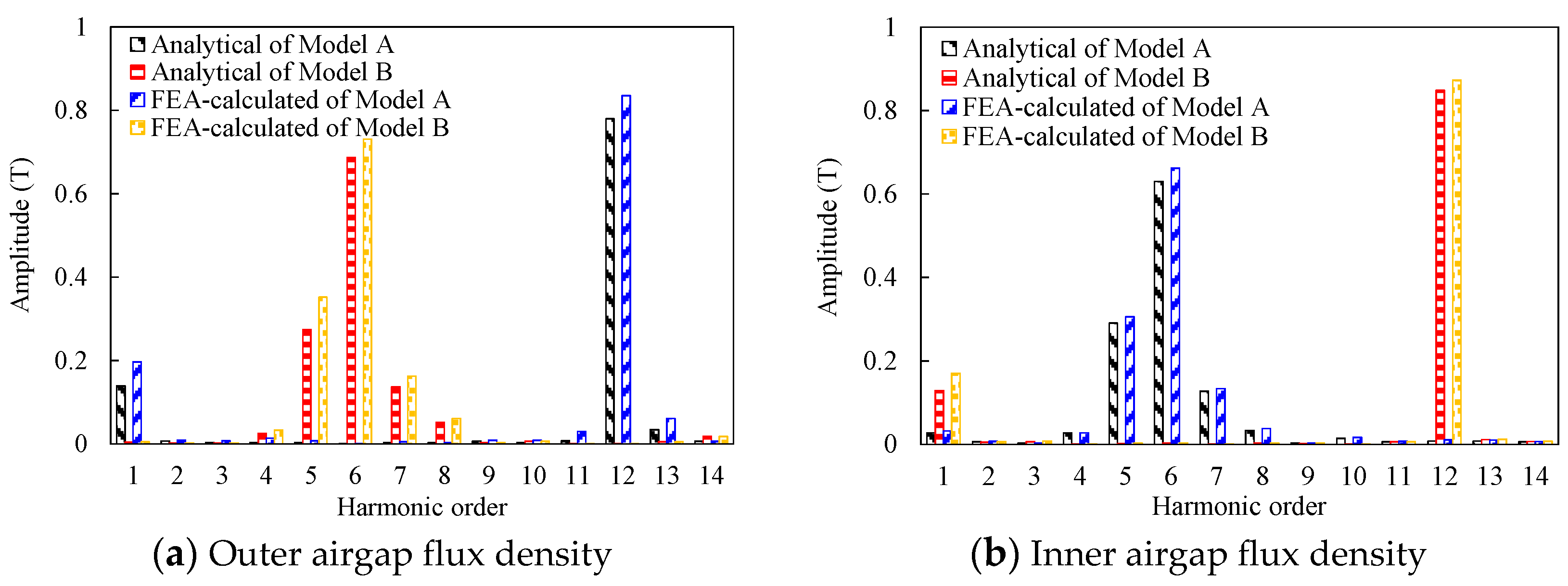
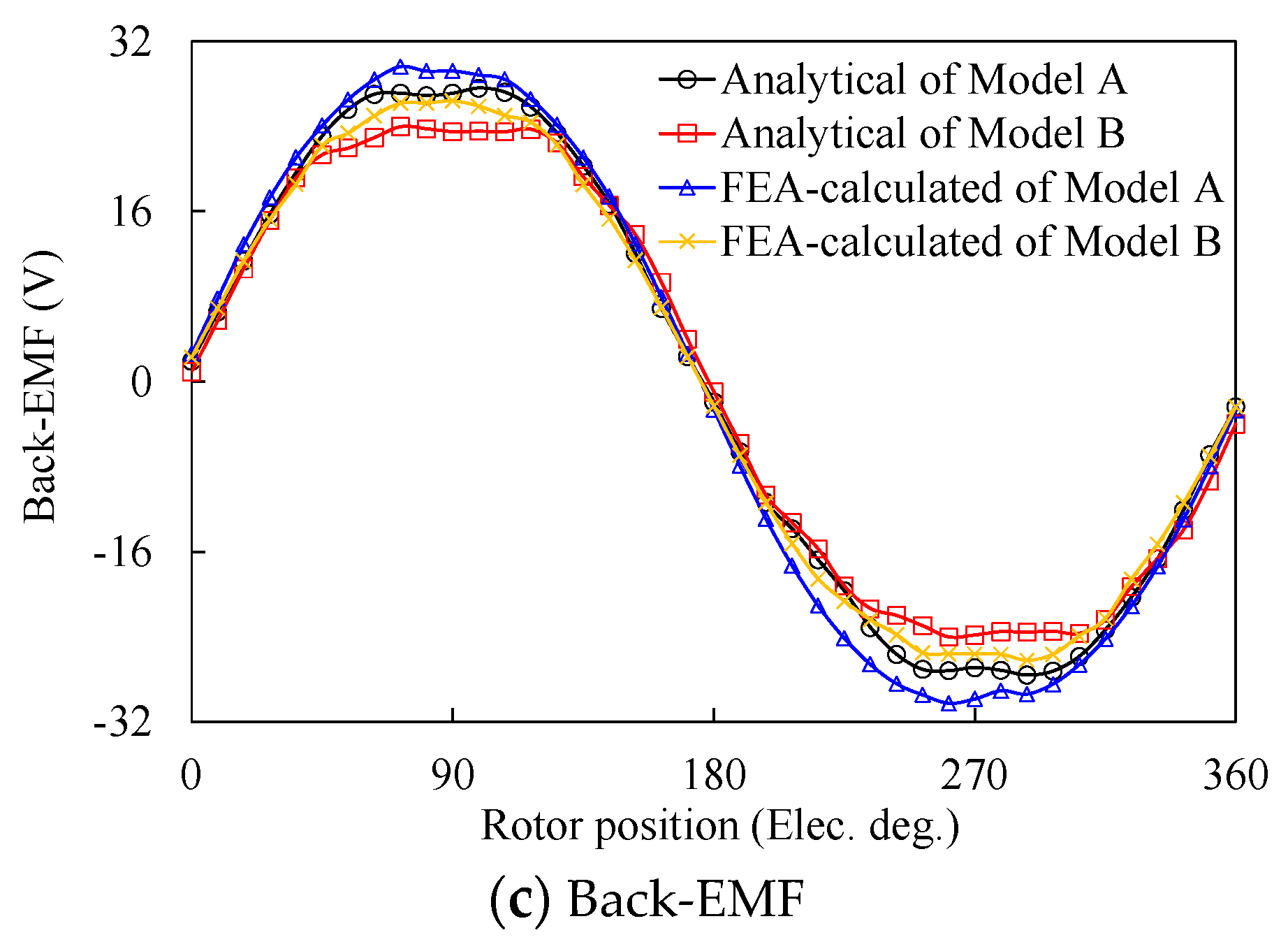
Figure 4.
Definition of design parameters for the rotor of the proposed DSPMMs.
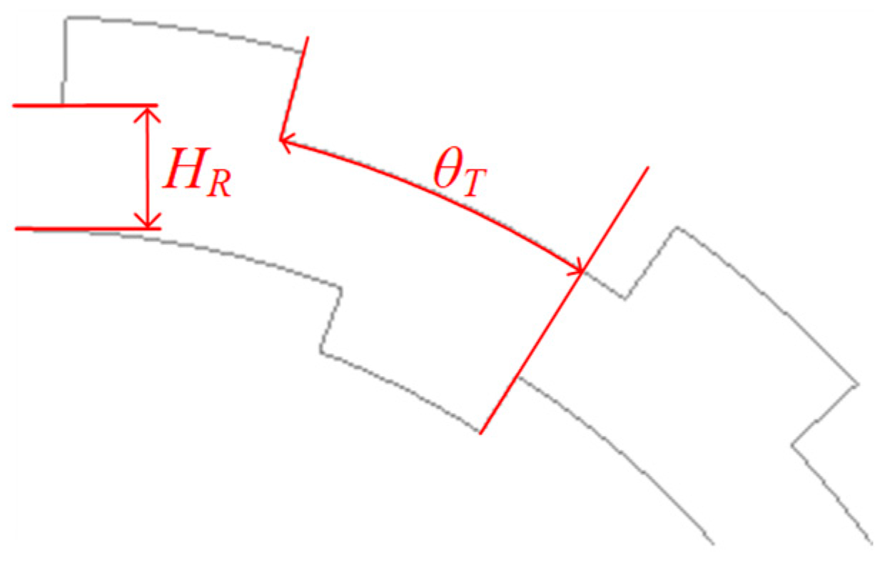
Figure 5.
Variation of average torque to HR.
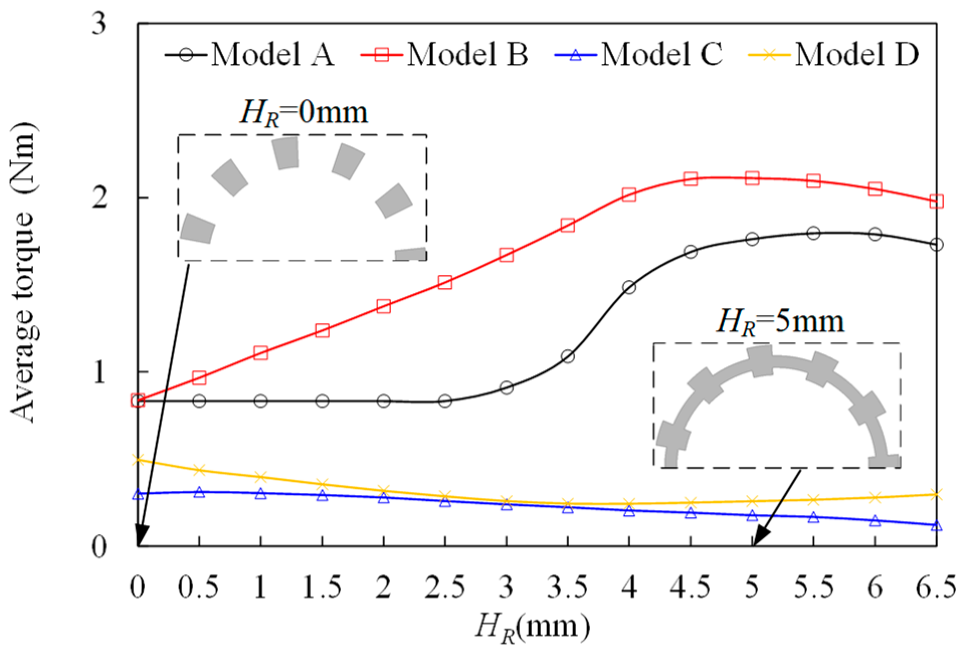
Figure 6.
Variation of average torque to θT.

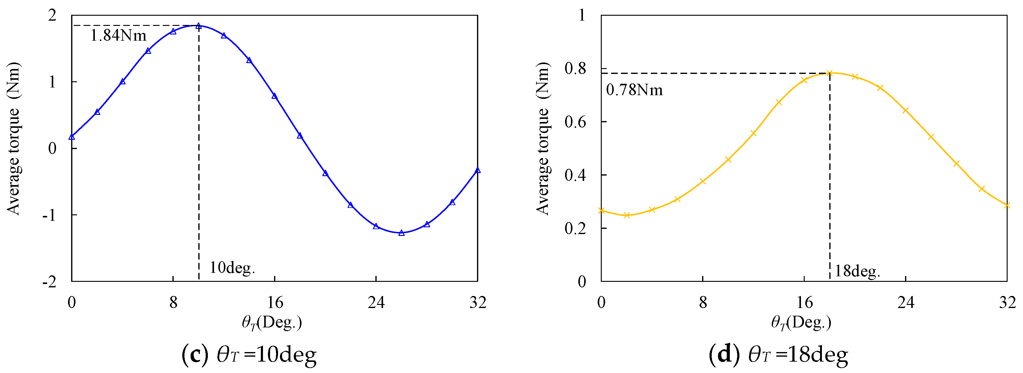
Figure 7.
Outer airgap flux density and corresponding harmonic analysis at no load state.
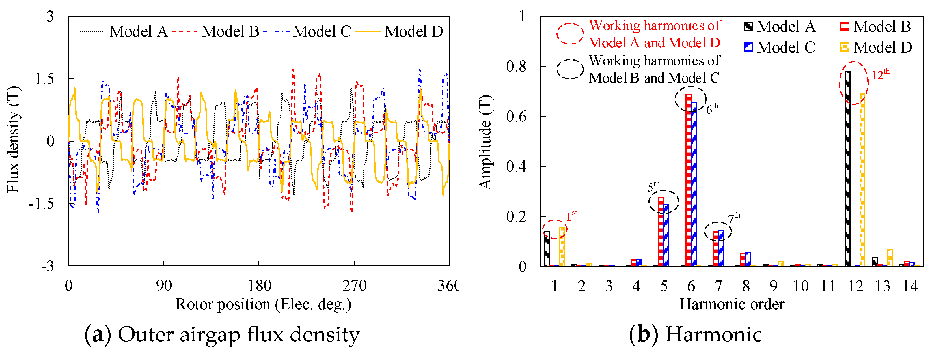
Figure 8.
Inner airgap flux density and corresponding harmonic analysis at no load state.
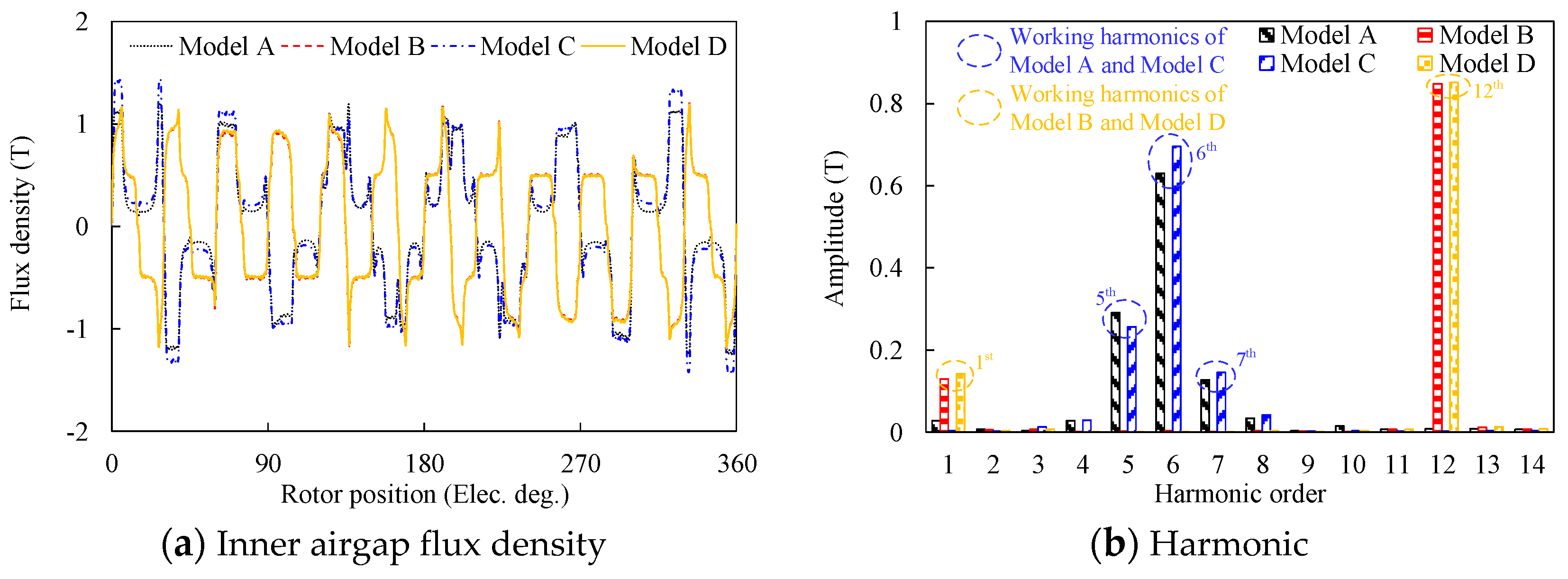
Figure 9.
Magnetic field distribution of these four models at no load state.
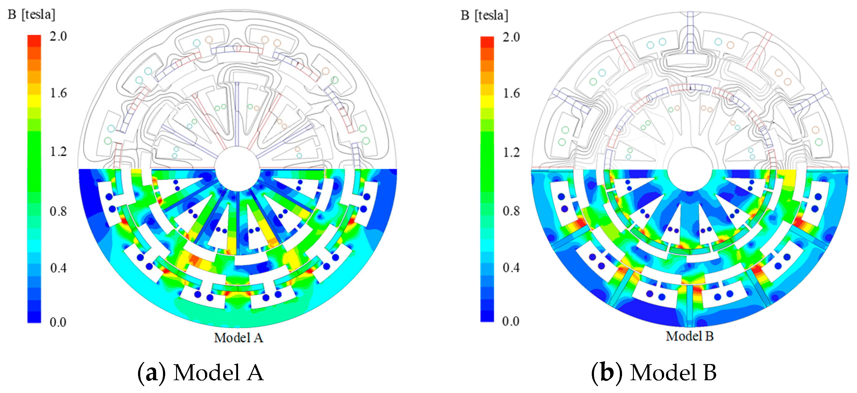
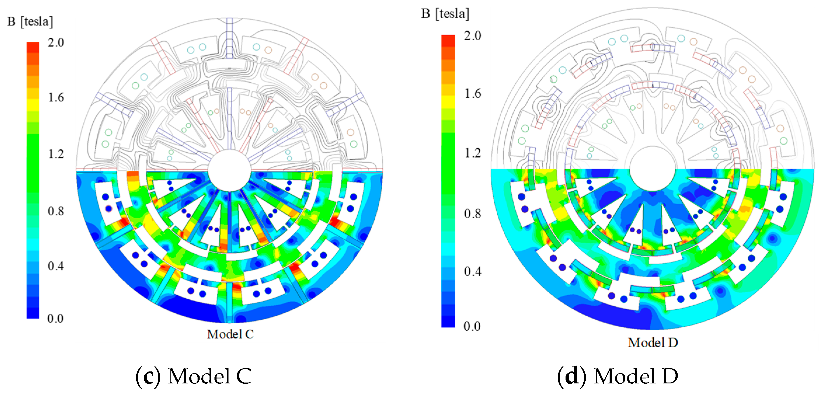
Figure 10.
Analysis of back-EMF and the corresponding harmonic spectra at no load state.
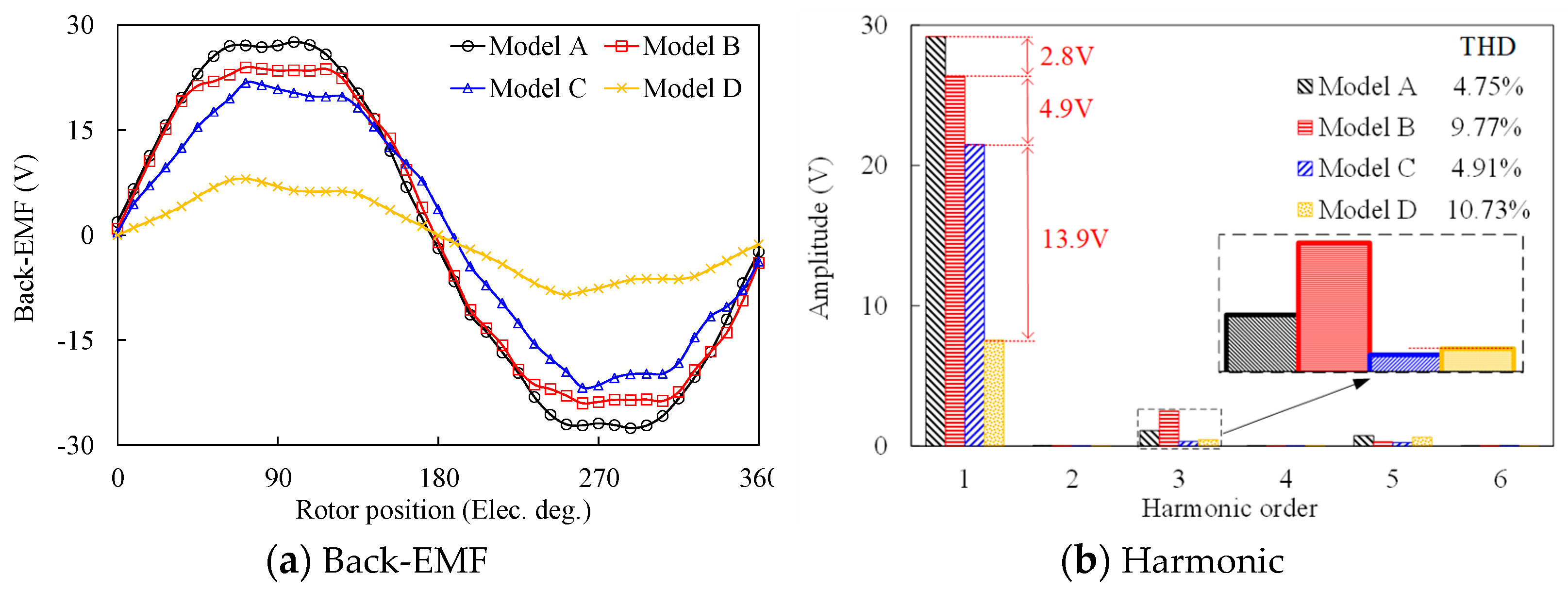
Figure 11.
The cogging torque and steady torque at rated state of these four machines.
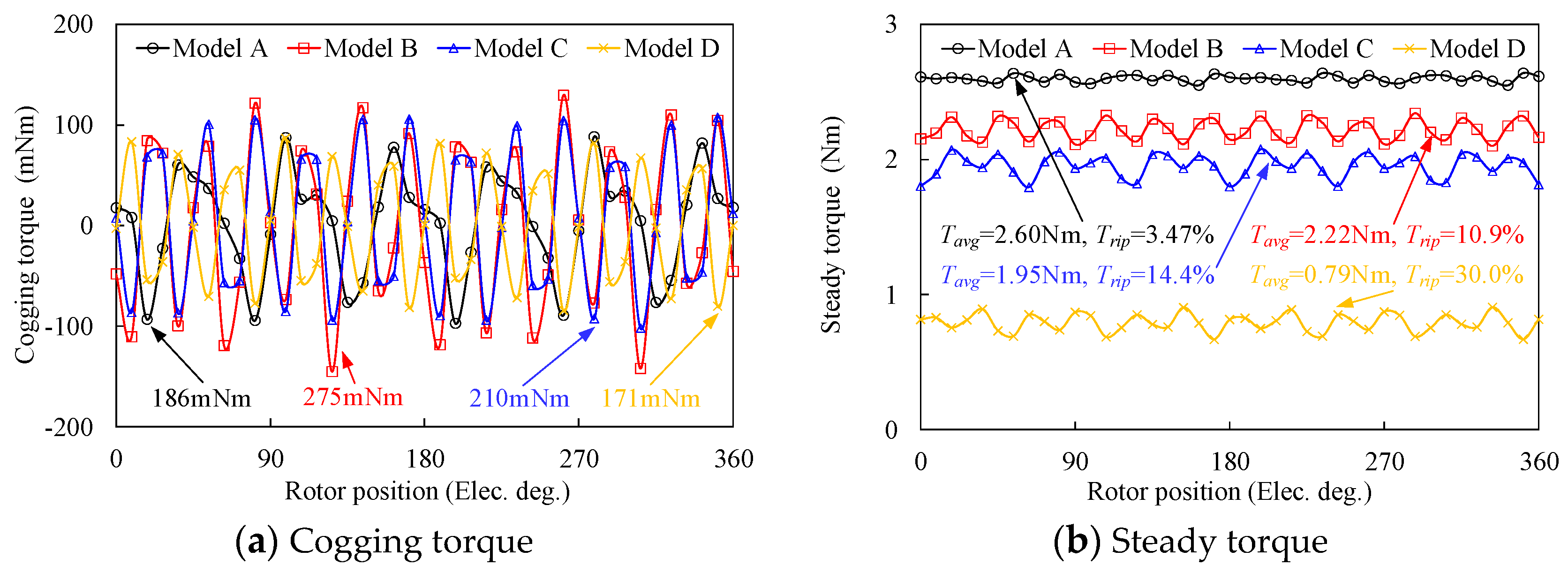
Figure 12.
Average torque versus current angle for these four models.
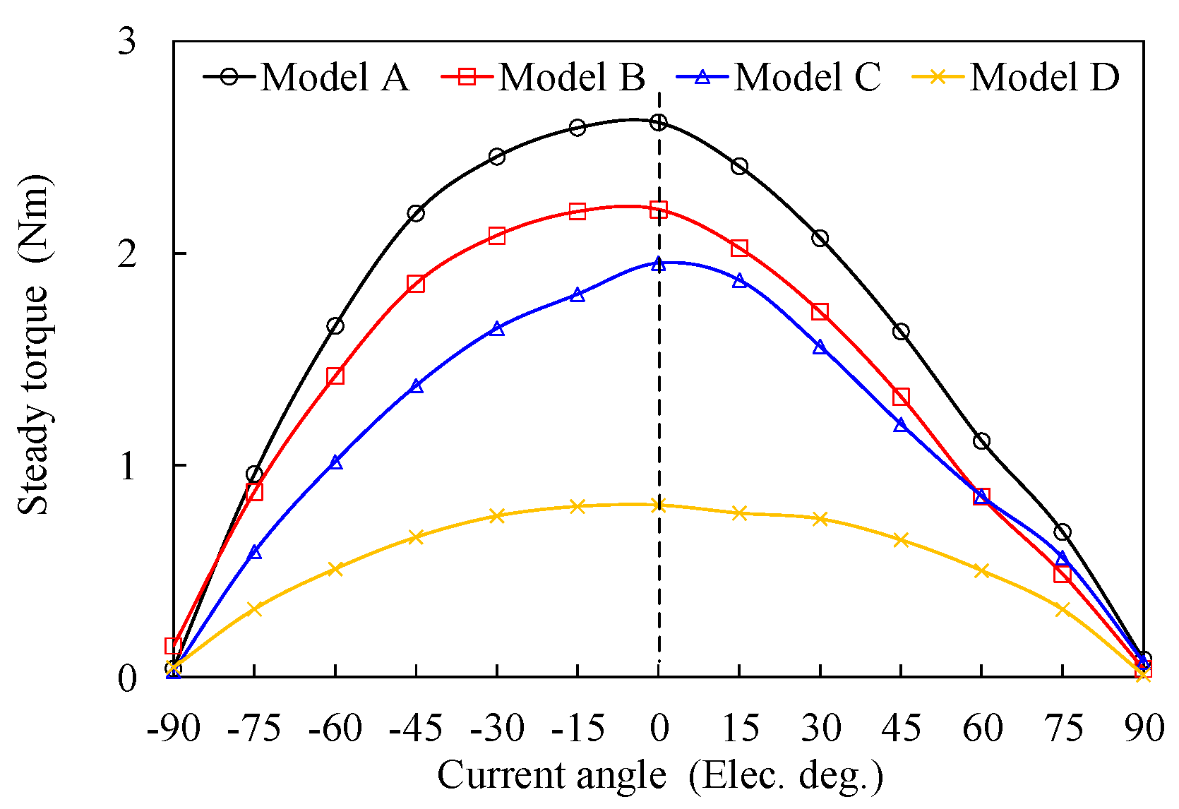
Figure 13.
The steady torques and torque ripples against copper loss for these four models.
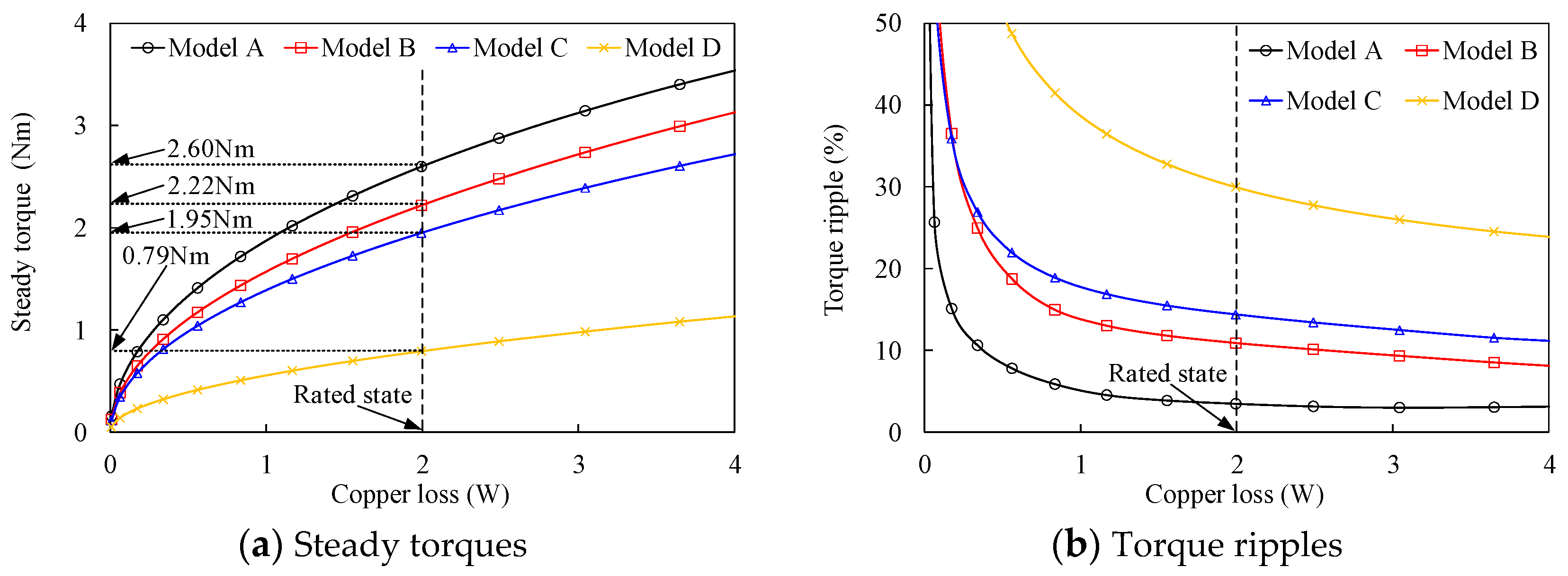
Figure 14.
Power factor and efficiency against copper loss for these four models.


Table 1.
Key design parameters of the proposed models.
| Items | Model A | Model B | Model C | Model D |
|---|---|---|---|---|
| Stator slot number | 12 | |||
| Outer/inner diameter of outer stator (mm) | 140/103 | |||
| Outer/inner diameter of inner stator (mm) | 76/20 | |||
| Outer/inner diameter of rotor (mm) | 102/77 | |||
| Active length of inner/outer airgap (mm) | 0.5/0.5 | |||
| PPN of rotor | 11 | |||
| Turn of the inner/outer armature windings | 128/128 | |||
| the inner/outer slot area (mm2) | 95/152 | |||
| Active stack length (mm) | 20 | |||
| PPN of the inner/outer PM | 6/12 | 12/6 | 6/6 | 12/12 |
| PM volume (mm3) | 94.5 | |||
| PM grade | N38SH | |||
| PM remanence (T) | 1.28 | |||
| PM coercive force (kA/m) | 955 | |||
| Rated speed (rpm) | 273 | |||
| RMS value of rated current (Arms) | 1.7 | |||
| HR (mm) | 5 | |||
| θT (deg.) | 7 | 2 | 10 | 18 |
Table 2.
Electromagnetic performances of these models at no load and rated states.
| Items | Model A | Model B | Model C | Model D |
|---|---|---|---|---|
| Amplitude of back-EMF (V) | 27.6 | 24.0 | 21.8 | 8.1 |
| THD of back-EMF (%) | 4.75 | 9.77 | 4.91 | 10.73 |
| Peak-to-peak cogging torque (mNm) | 186 | 275 | 210 | 171 |
| Steady torque at rated state (Nm) | 2.60 | 2.22 | 1.95 | 0.79 |
| Torque ripple (%) | 3.47 | 10.9 | 14.4 | 30.0 |
| Power factor | 0.91 | 0.90 | 0.75 | 0.67 |
| Output power (W) | 74.21 | 63.37 | 55.68 | 22.61 |
| Copper Loss (W) | 1.99 | 1.99 | 1.99 | 1.99 |
| Iron Loss (W) | 2.20 | 1.59 | 2.46 | 1.81 |
| Magnetic loss (W) | 0.26 | 0.08 | 0.08 | 0.29 |
| Efficiency (%) | 94.3 | 94.5 | 92.5 | 84.7 |
Disclaimer/Publisher’s Note: The statements, opinions and data contained in all publications are solely those of the individual author(s) and contributor(s) and not of MDPI and/or the editor(s). MDPI and/or the editor(s) disclaim responsibility for any injury to people or property resulting from any ideas, methods, instructions or products referred to in the content. |
© 2022 by the authors. Licensee MDPI, Basel, Switzerland. This article is an open access article distributed under the terms and conditions of the Creative Commons Attribution (CC BY) license (https://creativecommons.org/licenses/by/4.0/).
Share and Cite
MDPI and ACS Style
Ding, Z.; He, C.; Feng, C.; Yang, J. A New Dual Stator Permanent Magnet Machine Based on Field Modulation Theory. Sustainability 2023, 15, 281. https://doi.org/10.3390/su15010281
AMA Style
Ding Z, He C, Feng C, Yang J. A New Dual Stator Permanent Magnet Machine Based on Field Modulation Theory. Sustainability. 2023; 15(1):281. https://doi.org/10.3390/su15010281
Chicago/Turabian StyleDing, Ziyang, Chao He, Chunmei Feng, and Jianfei Yang. 2023. "A New Dual Stator Permanent Magnet Machine Based on Field Modulation Theory" Sustainability 15, no. 1: 281. https://doi.org/10.3390/su15010281
Note that from the first issue of 2016, this journal uses article numbers instead of page numbers. See further details here.