Article

A Study on the Drift of Spray Droplets Dipped in Airflows with Different Directions

by
Simone Pascuzzi
1,*,
Volodymyr Bulgakov
2,
Francesco Santoro
1,
Alexandros Sotirios Anifantis
1,
Semjons Ivanovs
3 and
Ivan Holovach
2
1
Department of Agricultural and Environmental Science, University of Bari Aldo Moro, Via Amendola 165/A, 70126 Bari, Italy
2
Department of Mechanics, Faculty of Construction and Design, National University of Life and Environmental Sciences of Ukraine, 03041 Kyiv, Ukraine
3
Faculty of Engineering, Latvia University of Life Sciences and Technologies, Liela str. 2, LV-3001 Jelgava, Latvia
*
Author to whom correspondence should be addressed.
Sustainability 2020, 12(11), 4644; https://doi.org/10.3390/su12114644
Submission received: 15 May 2020 / Revised: 3 June 2020 / Accepted: 5 June 2020 / Published: 6 June 2020
(This article belongs to the Special Issue Precision Agriculture and Sustainability)

Abstract

:
The European Directive concerning pesticide sustainable use establishes regulations to reduce the environmental drift throughout treatments to agricultural crops, particularly in nearby sensitive areas, such as water bodies, natural reserves and urban areas. The drift represents the fraction of mixture delivered by the sprayer that is not caught by the crop, and is the clearest cause of environmental pollution. Anti-drift nozzles are usually employed, and buffer zones are also maintained along the edges of the sprayed field to reduce drift production. The aim of this work was the theoretical study of the motion of the spray droplets delivered by a nozzle, dipped in downwards and/or lateral forced air flows. A mathematical model has been developed, consisting of a system of 2nd order differential equations, to simulate the motion of water droplets of different diameters within simultaneous different directions of air flow. The graphs, obtained by means of the numerical solution of the model, allow us to analyze the level of the droplets’ drift, according to their diameter and to the speed of the lateral and the downward air flows, respectively. A lateral airflow at a speed of 5 m · s 1 produced a drift in its direction until 1.70 m for droplets from 100 to 500 μm in diameter. For larger drops, the impact of the downward airflow is not very significant. The results obtained by the numerical solution of the mathematical model have been compared with the results of experimental tests carried out to evaluate the drift of spray produced by different nozzles.

1. Introduction

For many years, the distribution of agrochemicals was analyzed with the exclusive aim of maximizing the effectiveness of treatments in adversity controlling [1,2,3]. In more recent times, there was a crucial change in the public opinion approach towards plant protection products, characterized by a growing attention to the environmental impact caused by the dispersions of active substances, in the air and on the ground, throughout the treatments [4,5,6,7]. The European Directive, concerning the sustainable use of pesticides, among other provisions, imposes specific rules relating to the distribution phase of agrochemicals, when the dispersion possibility of toxic substances into the environment is maximum [8,9,10,11]. The drift is the most evident and responsible form of environmental pollution arising from the use of plant protection products [12,13,14,15]. According to the technical standard, the spray drift is the amount of agrochemicals that is pushed away from the treated area by the action of air flows (absolute drift) [16,17]. Therefore, the drift identifies the fraction of mixture delivered by the sprayer that is not intercepted by the crop and is instead dispersed in the surrounding environment, both far (transported by the wind: exodrift or atmospheric drift) and near (endodrift or runoff) the treated area [18,19,20]. The aforementioned Directive establishes the need for drift reduction during treatments, particularly in nearby sensitive areas, such as water bodies, natural reserves and urban areas [21,22,23,24].
Spray drift is usually mitigated using anti-drift nozzles (direct mitigation) or by inserting buffer zones along the edges of the sprayed field (indirect mitigation), whose widths have to be strictly linked to the sprayer typology, nozzles, and operational parameters of the sprayer [25,26,27]. It is well known that technical guidelines classify spraying equipment in agreement with a drift risk standard, which is evaluated by means of comparison measures between the drift produced by the candidate spraying equipment and a reference device, which is chosen as being representative of the most common spraying technique assumed for a specific scenario [28,29,30]. It is also necessary to remember the drift potential of the spray, which represents the percentage of the initial volume of the spray that remains suspended in the air after the sprayer transit [31,32]; it represents the spray liquid fraction most susceptible to drift from the treated area due to the air flows during chemical application [33,34,35]. For example, during treatments on herbaceous crops, which are usually carried out with a horizontal boom spraying machine, the sprayed droplets delivered by the nozzles form a wake due to the forward speed [36,37]. This wake, which tends to float in the air for a certain period of time, constitutes a “potential drift” and becomes an effective drift if the transversal component of the wind carries it outside the treated area [38,39].
It is known that the characterizing element of these sprayers for field crops is the horizontal bar, formed by a metal reticular structure, which supports the nozzles and the pipes for adding the liquid to them. These sprayers usually are low pressure units. Furthermore, tanks and booms may be mounted on tractors, designed as trailered units, powered and pulled by a tractor, or even self-propelled. Booms may range in length from 8–36 m and their height must be easily adjustable from 30–180 cm above the target, to ensure good nozzle performance and spray pattern overlap. Some booms are self-leveling to reduce travel undulation and provide more uniform application. Boom sprayers produce a thrown-out jet, so that the transportation of the droplets to the target takes place only for their kinetic energy [40,41]. This can cause drift problems in the presence of wind and to overcome this drawback, air-assisted boom sprayers can be used [42,43]. These types of sprayers are equipped with a mechanical spraying system assisted by the active transport of the droplets by means of an air flow produced by a fan, centrally mounted above the horizontal boom [44]. The air is sucked by the fan and sent along the boom through a flexible plastic pipe, provided at the bottom with a series of holes to have the spray droplets interested by an uninterrupted airflow from top to bottom. In this way, the air blade hits and directs the spray on the vegetation placed below and inside it, creating a turbulence that facilitates the deposit on the target. The downward air flow is then able to produce: (i) greater coverage; (ii) better penetration; (iii) and the possibility of treating even in the presence of moderate intensity wind, reducing drift phenomena.
Several studies analyzed the motion of sprayed droplets, in which this process is described considering different operative conditions [45,46,47,48]. For example, the motion of the droplets has been studied considering zero as their initial speed, or with an initial speed higher than zero [49]. In another research, the motion of droplets was described taking into account their initial speed and considering, as a first approximation, a linear proportion between air resistance force and droplet speed, even if this passive force is quadratically dependent on droplet speed [50]. Despite all of these studies, no one has ever been carried out which considers the impact on the droplets of lateral and downward airflow, so the aim of this work was the theoretical study of the motion of the spray droplets delivered by a nozzle, dipped in downwards and/or lateral forced air flows. Experimental tests have also been carried out to validate, with their initial results, the proposed theoretical model.

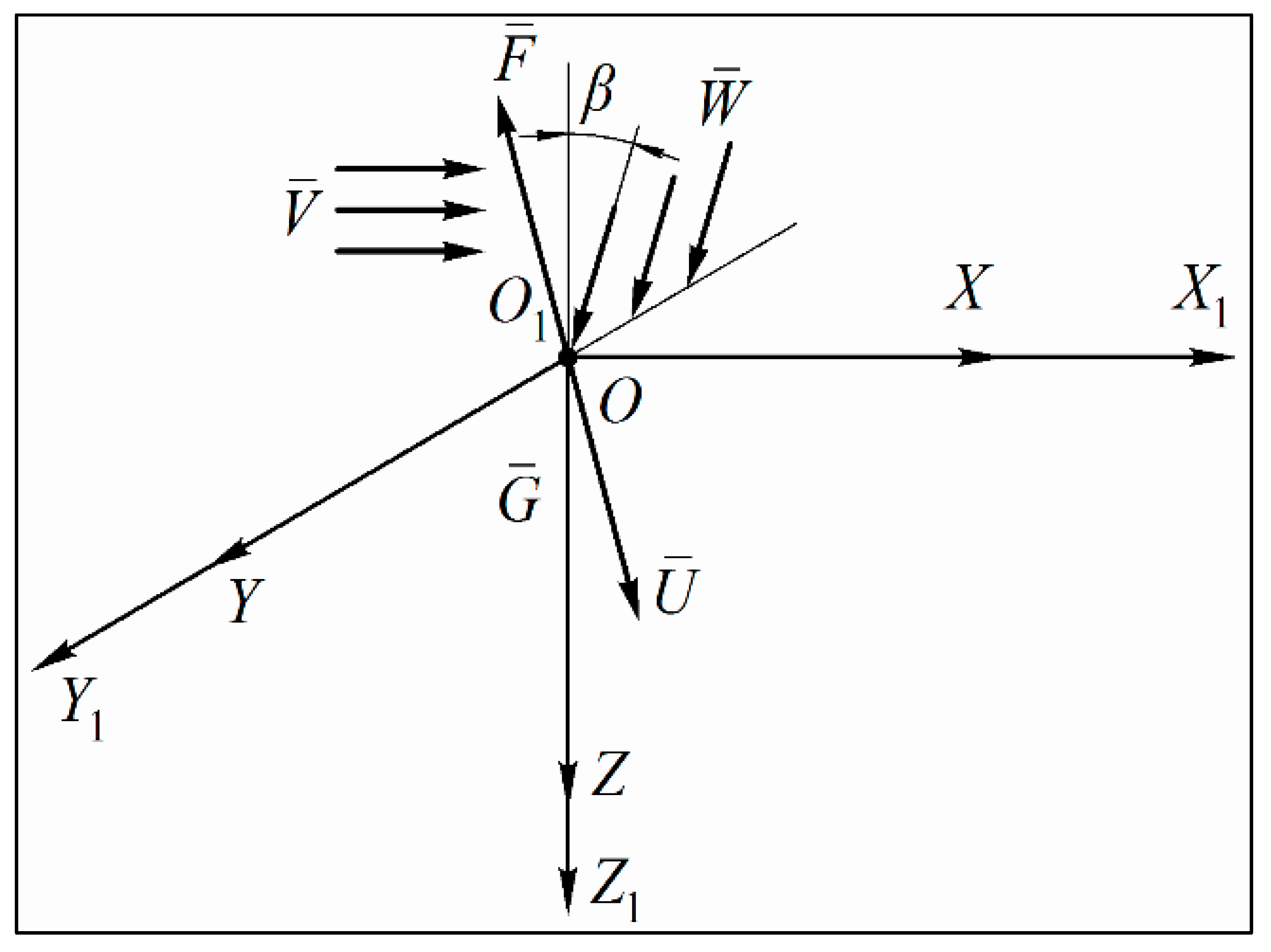
2. The Mathematical Model

First of all, we will suppose that the device creating the necessary downward airflow is able to ensure the flow existence in the area where the droplets leave the nozzle: at the initial time of its motion, the droplet is already dipped in the downward flow. Furthermore, at the same initial time of its motion out of the nozzle, the droplet is also hit by lateral airflow (which simulates the wind). We will assume that the lateral airflow acts perpendicular to the direction of the movement of the aggregate along the field and it has constant speed V ¯ . The downward airflow also moves at constant speed W ¯ with a line of action directed at an angle β to the vertical. The direction of vectors V ¯ and W ¯ is shown in Figure 1.
Therefore, the lateral airflow and the downward airflow form a mobile air medium in which the droplet is located in the moment of its emission from the sprayer. Since the mass of the droplet and its dimensions are rather small, the flow around the droplet can be neglected, and we can assume, as a first approximation, that the droplet moves under the impact of the lateral airflow at speed V ¯ and of the downward flow at speed W ¯ . In this case, we also neglect the gravity force, assuming that the droplet is weightless.
As a result, the droplet, in the case when it flies out of the sprayer without an initial speed, will move under the airflow action at constant speed V ¯ + W ¯ .
Considering that both flows are uniform, we can assume that each point of the mobile medium has the same speed V ¯ + W ¯ and, no matter at which point of this air medium the droplet is located, it will still moves at speed V ¯ + W ¯ , so the air medium acts as a uniform speed carrier for the droplet. In this scenario, any coordinate system, whose origin is located at an arbitrary point of the mentioned medium and moves with a rigid connection to it, is inertial and moves without acceleration [51].
If the initial speed ( U ¯ 0 ) of the droplet coming out of the nozzle, as well as the gravity force G ¯ on the droplet and the resistance force ( F a ) to the droplet motion in the air medium, are taken into account, the droplet will move in the considered coordinate system and thus in relation to the above-mentioned airflow at a time-dependent speed U ¯ = U ¯ ( t ) . Therefore, it can be considered that the droplet has a complex movement consisting of the composition of its carrying movement together with the air flow at constant speed V ¯ e = V ¯ + W ¯ , and a relative movement inside the airflow at a variable speed V ¯ r = U ¯ ( t ) . Consequently, its absolute speed ( V ¯ a ) in relation to the inertial coordinate system will be:
V ¯ a = V ¯ e + V ¯ r
or, taking into account the obtained values for the carrying and the relative speeds:
V ¯ a = V ¯ + W ¯ + U ¯ ( t )
Considering the aforesaid, in order to study the relative movement of a droplet, it is necessary to introduce a fixed Cartesian coordinate system X 1 O 1 Y 1 Z 1 whose origin O 1 is located at the point where the droplet comes out of the nozzle. We will direct the X 1 axis in the direction of the lateral air flow (wind), the Z 1 axis vertically down and the Y 1 in the forward direction of the boom sprayer and tractor across the field.
In addition, we also introduce a moving Cartesian coordinate system X O Y Z rigidly connected with the moving air flow (carrying medium) [52]. Without loss of generality, at the initial time, we will choose for this coordinate system the same origin and the same axis directions of the X 1 O 1 Y 1 Z 1 coordinate system. Thus, at the initial time (the moment when the droplet leaves the nozzle), the two coordinate systems coincide. It is obvious that both the absolute coordinate system X 1 O 1 Y 1 Z 1 (being at rest), and the moving one, X O Y Z , are inertial. The relative movement of the droplet will be considered in the moving coordinate system X O Y Z as the movement of a droplet in the air flow; this will make it possible to evaluate the value of the relative speed and the movement of the droplet in a moving air medium at an arbitrary time. Then, we will make a translation to the absolute speed and to the absolute movement of the droplet, which is the main goal of this work.
To compile the differential equation of motion of the droplet relative to the moving air medium (in the coordinate system X O Y Z ), we need to represent the two coordinate systems X 1 O 1 Y 1 Z 1 , X O Y Z , the direction of the lateral airflow, the direction of the downward airflow and the forces acting upon the droplet while it moves in the two airflows, on an equivalent scheme (Figure 1).
Based on the fundamental law of the dynamics of a material point, using the developed equivalent diagram of forces, we can write the equation of the motion of a droplet relative to the moving air medium ( X O Y Z coordinate system):
m a ¯ = F ¯ + G ¯ m d U ¯ d t = F ¯ + m g ¯
where:
  • a ¯ = d U ¯ d t : acceleration of the motion of a droplet in the mobile air medium, m · s 2 ;
  • m: mass of the droplet, kg;
  • g ¯ : gravity acceleration, m · s 2 .
It is possible to evaluate the value of the resistance force acting on the droplet due to its movement in the air medium. It is usually assumed that this force has a quadratic dependence on the droplet speed in the air medium:
F = m g V s o 2 · U ¯ 2
where:
  • V s o 2 : square value of the soaring rate of a droplet, m 2 · s 2 ;
  • g : gravity acceleration, m · s 2 .
Considering equation (3), the differential equation of the relative motion of the liquid droplet in a vector form is:
m d U ¯ d t = m g V s o 2 · U ¯ 2 · U ¯ | U ¯ | + m g ¯
where:
  • U ¯ | U ¯ | : unit vector indicating the direction of the relative movement of the droplet (the direction of the velocity vector U ¯ ( t ) in a moving airflow);
  • | U ¯ | : value (modulus) of vector U ¯ .
The “–” sign indicates that vector F ¯ , as the vector representing the resistance force acting on the droplet due to its movement in the air medium, is directed opposite to the relative velocity vector U ¯ ( t ) .
Dividing both sides of Equation (5) by mass m , the following vector differential equation arises:
d U ¯ d t = g V s o 2 · U ¯ 2 · U ¯ | U ¯ | + g ¯
Taking into account that: (i) the vector U ¯ ( t ) = { U x ( t ) , U y ( t ) , U z ( t ) } , where U x ( t ) , U y ( t ) , U z ( t ) are the U ¯ ( t ) vector projections on axes O X , O Y and O Z , respectively; (ii) and correspondingly, the module of the indicated vector U ¯ ( t ) is given by:
| U ¯ ( t ) | = [ U x ( t ) ] 2 + [ U y ( t ) ] 2 + [ U z ( t ) ] 2
the vector differential Equation (6) can be reduced using its projections on the axis of the Cartesian coordinate system X O Y Z to the following system of differential equations [53]:
{ d U x d t = g V s o 2 · | U ¯ ( t ) | · U x ( t ) d U y d t = g V s o 2 · | U ¯ ( t ) | · U y ( t ) d U x z d t = g V s o 2 · | U ¯ ( t ) | · U z ( t ) + g
Furthermore, switching over from the relative speed U ¯ ( t ) to the relative motion r ( t ) = { x ( t ) , y ( t ) , z ( t ) } of the droplet in the X O Y Z coordinate system, the following system of second-order differential equations with variable coefficients is obtained [54,55]:
{ d 2 x d t 2 = g V s o 2 · | d r ¯ d t | · d x d t d 2 y d t 2 = g V s o 2 · | d r ¯ d t | · d y d t d 2 z d t 2 = g V s o 2 · | d r ¯ d t | · d z d t + g
where:
| d r ¯ d t | = [ d x d t ] 2 + [ d y d t ] 2 + [ d z d t ] 2
To solve the system (9) using numerical methods, the following initial conditions of motion (at t = 0 ) have been used:
x = 0 ;   y = 0 ;   z = 0 ;   d x d t = U x = 0 ;   d y d t = U y ( 0 ) = 0 ;   d z d t = U z ( 0 ) = μ 2 Δ p ϱ
where:
  • μ : coefficient strictly linked to the characteristic of the nozzle, dimensionless;
  • Δ p : working pressure of the liquid in the system, Pa;
  • ϱ : liquid density, kg   m 3 .
For the numerical analysis, we considered: (i) pure water as liquid processed by the nozzle, and (ii) and the same pressure Δ p used in the experimental tests; therefore, it has given:
  • ϱ = 1000 kg   m 3 ;
  • Δ p = 0.2 · 10 6 Pa.
Furthermore, it has been assumed [46]:
μ = 0.97.
Finally, considering Equations (11) has given:
d z d t = U z ( 0 ) = 0.97 · 2 · 0.2 · 10 6 1000 = 19.4 m · s 1   20   m · s 1 .
The limit of integration of the system of Equations (9) are from t = 0 to t 1 , where t 1 is the time required by the droplet to reach the target surface that has been considered, taking into account the equipment constructive layout used in the experimental tests, located at 0.5 m from the nozzle. Therefore, after a series of transformations (Appendix A) from the solution of the system of the second-order differential Equations (9), it is possible to obtain the complete motion equation of the droplet from the instant in which it is delivered by the nozzle to the instant in which it reaches the target surface.

3. Materials and Methods

Experimental drift evaluation tests were carried out using custom indoor laboratory equipment (Figure 2), composed of the following systems: (i) liquid feeding and spraying; (ii) production of both horizontal air flow and vertical downward air flow; (iii) collection of the sprayed liquid [56].
The liquid feed and spray system included a water tank with a filter, an electric motor linked to a pump, a pressure gauge, a flow rate regulator and a nozzle. The horizontal airflow generation system included a centrifugal fan and a horizontal outlet chute oriented towards the nozzle, so as to create a wind tunnel. The system for generating the vertical downward air flow consisted of a centrifugal fan and a pipe ending with a diffuser oriented downwards and positioned: (i) at an angle of 30° with respect to the vertical surface; (ii) at a distance of 0.06 m from the nozzle axis; (iii) and 0.03 m below the nozzle itself’s exit plane. The droplet collection system consisted of a test bench positioned 50 cm below the nozzle. According to the technical standard in force, this test-bench was formed by a patternator with grooves 100 mm wide and 80 mm deep, which was able to assess the transverse volume distribution of the spray delivered by the above nozzle [57]. Graduated spray liquid measuring cylinders with a capacity of 500 mL and a scale graduation of 10 mL were then used to collect the water from each groove. The nozzle was installed in such a way that the spray jet was perpendicular to the direction of the patternator grooves. Furthermore, the geometric axis of the nozzle hole passed between the grooves corresponding to the measuring cylinders 5 and 6.
The following two nozzles, currently mounted on horizontal boom sprayers in Ukraine, were considered: (i) the standard flat spray nozzle ST 110-02 (Lechler GmbH, Germany); (ii) and the low drift ID 120-02 (Lechler GmbH, Germany). For both nozzles, the operating pressure 0.2 MPa was considered, as it is usually adopted by the operators during the treatments. The flow rate of each individual nozzle was evaluated for the considered operative pressure by collecting the liquid delivered during a working time of 60 s, and the mean value was assumed from five measurements [58]. The nozzles’ flow-rates were checked with a measurement error of less than ±2.5% of the true value [57]. According to the technical standard, it was verified that the flow rate of each nozzle did not deviate by more than 10% from the nominal flow rate indicated by the nozzle manufacturer [57]. The measured delivered flow rate related to the ST 110-02 nozzle was 0.647 L/min−1, whereas the one related to the low drift ID 120-02 was 0.648 L/min−1. In such a way, both of the nozzles delivered nearly the same liquid flow rate. Furthermore, according to the data supplied by the manufacturer, the droplet population produced by the ST 110-02 nozzle under the operative pressure of 0.20 MPa was characterized by a volume median diameter (VMD) of about 250 µm; conversely, the droplet population produced by the low drift ID 120-02 under the same operative pressure had a volume median diameter (VMD) of about 350 μm [59].
The experimental tests aimed to assess the transverse volume distribution of the spray delivered by each tested nozzle, and then the drift as a function of the changes in the lateral and in the downward air flow speeds. In particular, the following variants were considered:
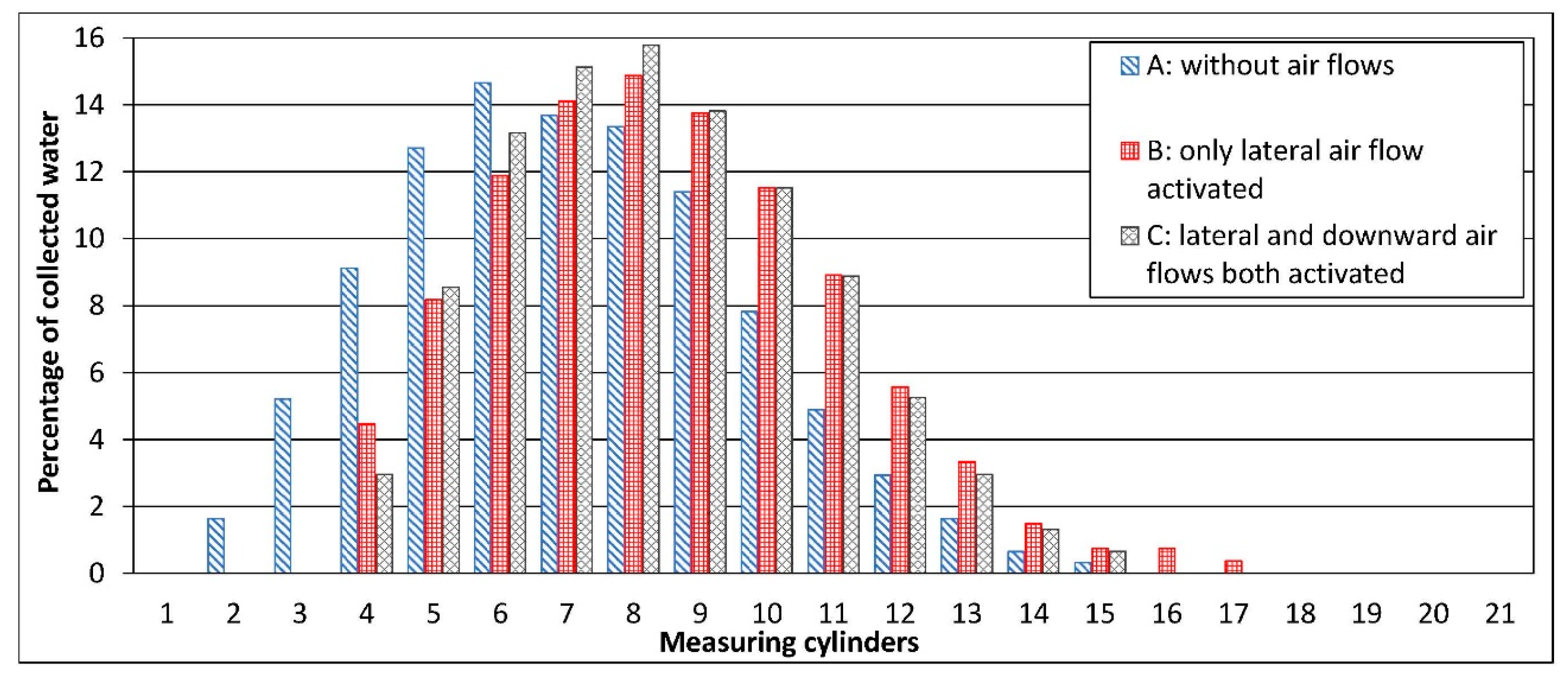
  • spraying without the action of lateral and downward air flows;
  • spraying under the action of a lateral air flow;
  • spraying under the simultaneous action of a lateral air flow and a downward air flow.
The tests were conducted considering the pressure of 0.20 MPa and the following values for the lateral air flow speed: 0 m · s 1 (no lateral wind); 3.0; and 5.0 m · s 1 . Finally, the following downward air flow speeds were considered: 0 m · s 1 (no downward air flow) and 15 m · s 1 . The collection time of the liquid sprayed on the test bench was 1 min [57]. Each test was repeated three times. Air speeds were measured using a hot-wire anemometer (LSI model BS-V101) connected to a LSI six-inputs “BabucM” BSA020 multiple data acquisition device with a 5000-samples memory (32 kb EEPROM), and the resulting data were then processed using a personal computer.

4. Results and Discussion

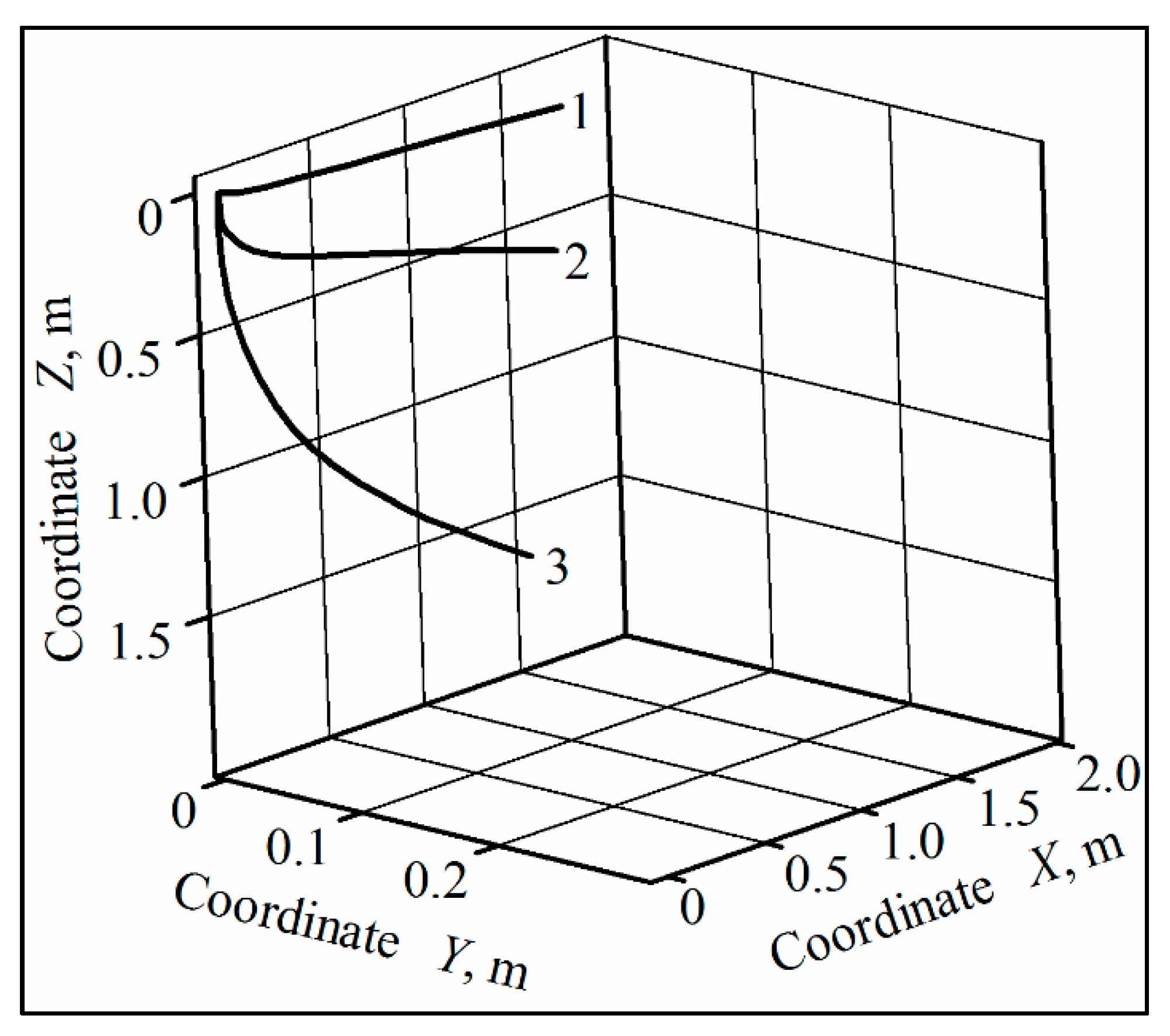
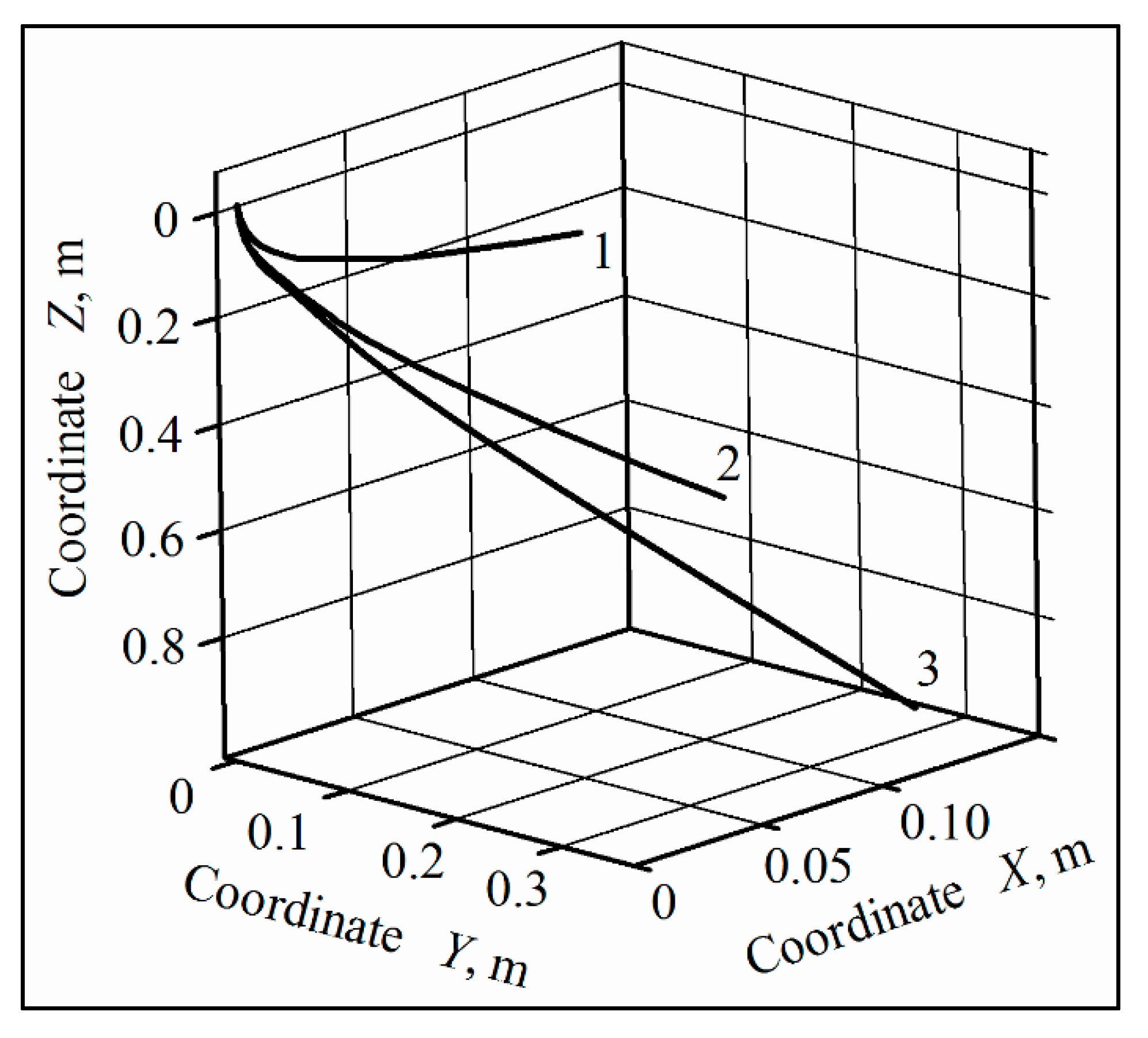
4.1. Numerical Results

The numerical computations was carried out considering the nozzle installed downward at an angle β = 30 ° with respect to the vertical plane, and the initial speed of the droplets at the exit from the nozzle equal to U 0 = 20   m · s 1 Furthermore, calculations took into account the following operating conditions: (i) droplets diameter d 1 = 100 , d 2 = 250 and d 3 = 500 μm; (ii) lateral airflow speeds V 1 = 3.0 , V 2 = 5.0 and V 3 = 7.0 m · s 1 ; (iii) downward air flow speed W 1 = 0.0 (not activated) and activated downward air flow at speeds W 1 = 15.0 and W 3 = 30.0 (activated) m · s 1 . The value of the soaring rate of the droplets corresponding to each of the aforesaid diameters was determined by means of the Stokes law [60,61]. As aforesaid, t1 is the time to reach the target surface placed at 0.5 m from the nozzle. In order to assess the drift of the droplets in the operative conditions characterized by the no activated downward air flow, it has been assumed that t1 = 0.35 s; conversely, it has been chosen that t1 = 0.035 s to determine the drift of droplets of different diameters when the downward air flow was activated [62,63].
It turned out that in 0.35 s, the lateral airflow at a speed of 5 m · s 1 drifts in its direction up to 1.70 m, the droplets of diameter from 100 to 500 μm; whereas in the same time the following distances were covered in the direction of the target surface, respectively: (i) 0.11 m by 100 μm diameter droplets; (ii) 0.60 m by 250 μm diameter droplets; (iii) and 1.71 m by 500 μm diameter droplets (Figure 3). Furthermore, keeping the downward airflow off, in 0.035 s, the 100 μm diameter droplets, affected by the lateral airflow at a speed of 5 m · s 1 , drifted in its direction up to 0.17 m, whereas they reached a distance of only 0.03 m toward the target surface. Conversely, the same droplets, under the impact of both the downward flow at a speed of 15 m · s 1 and the lateral airflow at a speed of 5 m · s 1 , covered a distance toward the target surface of 0.48 m.
For larger drops, the impact of the downward airflow is less important. For instance, with no activated downward air flow and with lateral air flow speed of 5 m · s 1 , in 0.035 s, a 250 μm diameter droplet covered a distance toward the target surface of 0.23 m. The same droplet, under downward flow of 15 m · s 1 and a lateral air flow speed of 5 m · s 1 , travelled 0.60 m. For the 500 μm diameter droplet, these distances were 0.50 m and 0.76 m, respectively. Increasing the speed of the downward flow to 30 m · s 1 at the same wind speed of 5 m · s 1 , the 250 μm diameter droplet covered a distance of 0.90 m toward the target surface (Figure 4).

4.2. Experimental Results

The patterns of the transverse distribution of the spray delivered by the standard flat spray nozzle ST110-02, under the pressure of 0.2 MPa, are shown in the histograms of Figure 5, where the percentage of collected liquid for each measuring cylinder is reported as regards the entire amount of the collected liquid. Moreover, Figure 5 reports the histograms obtained with the following operative conditions, respectively: (i) without the action of any air stream (A-type histogram in Figure 5); with the action of the lateral air flow at 3 m · s 1 (B-type histogram in Figure 5); (ii) and with the simultaneous activation of lateral air flow at 3 m · s 1 and downward air flow at 15 m · s 1 (C-type histogram in Figure 5).
In the absence of air flow, a fairly symmetrical profile is detected, with most of the liquid collected from the measuring cylinders placed near the nozzle. With an activated lateral air flow of 3 m · s 1 , a more uniform distribution of the liquid in the measuring cylinders is produced, making the profile more “flat” but, at the same time, it carries the droplets in its direction, causing them to drift. Figure 5 shows that without the lateral air flow, the spray droplets are collected by the measuring cylinders from 2 to 15, i.e., over an overall target width of 1.4 m. Conversely, with an activated lateral air stream of 3 m · s 1 , the spray droplets are collected by the measuring cylinders from 3 to 20, i.e., over an overall target width of 1.7 m. The drift produced in comparison with the previous operative condition is then 0.3 m. The same phenomenon occurs with the activated lateral airflow of 5 m · s 1 , even if in this case the spray droplets are collected by the measuring cylinders from 3 to 21, i.e., over an overall target width of 1.8 m and 0.4 m drift, compared with no activated lateral airflow.
With regard to the nozzle position, the lateral air flow at 5 m · s 1 moved the spray droplets in its direction up to the measuring cylinders n. 21, which means a distance of about 1.50 m from the axis of the nozzle with a difference as low as 9% from the corresponding value obtained by the numerical solution if 250 μm diameter droplets are considered.
The activation of the downward air flow with a speed of 15 m · s 1 , in addition to the lateral one of 3 m · s 1 , produces a clear modification of the transverse distribution diagram (C-type histogram in Figure 5). The downward current predominates over the lateral one and the lateral drift is then drastically reduced. The results obtained with a lateral air flow at a speed of 5 m · s 1 , combined with a downward air flow at speed of 15 m · s 1 , show a behavior of the spray droplets delivered by the nozzle substantially similar to that corresponding to the lateral airflow of 3 m · s 1 . Moreover, in this case, the experimental behavior of the droplets is absolutely comparable with the numerical results, which have shown that the 250 μm diameter droplets reached the target surface, with a drift of just over 0.10 m in the direction of the lateral air flow. The aforesaid experimentally obtained results agree with those ones obtained in previous studies [39,59,64].
The patterns of the transverse distribution of the spray delivered by the low drift nozzle ID 120-02, under the pressure of 0.2 MPa, are shown in the histograms of Figure 6, for the following operative conditions, respectively: (i) without the action of any air stream (A-type histogram in Figure 6); with the action of the lateral air flow at 5 m · s 1 (B-type histogram in Figure 6); (ii) and with the simultaneous activation of lateral air flow at 5 m · s 1 and downward air flow at 15 m · s 1 (C-type histogram in Figure 6). Each histogram represents the percentage of collected liquid of the corresponding measuring cylinder as regards the entire amount of the collected liquid.
The distribution profile is quite symmetrical as regards to the position of the nozzle in the absence of air flow (A-type histogram in Figure 6) and the spray droplets are collected by the measuring cylinders from 2 to 15, i.e., over an overall target width of 1.4 m. The activation of the lateral air flow, both with a speed of 3 m · s 1 and of 5 m · s 1 , produces a displacement of the spray droplets in its direction even with the use of the low drift nozzle ID 120-02. For example, the B-type histogram of the Figure 6 shows the transverse distribution profile obtained with the lateral air flow of 5 m · s 1 . The lateral air flow does not modify the shape of the distribution profile obtained in the absence of the lateral air flow, but substantially “relocates” it, affecting the measuring cylinders from 4 to 17, i.e., the droplets undergo a drift of 0.2 m. Taking into account the position of the nozzle, the lateral air flow of 5 m · s 1 has moved droplets in its direction up to the measuring cylinder n. 17, i.e., at a distance of about 1.20 m from the axis of the nozzle; this value deviates by 8% from the one obtained with the numerical solution considering 350 μm diameter droplets.
The activation of the downstream air flow of 15 m · s 1 did not produce substantial changes in the transverse distribution profile, as occurred with the ST110-02 nozzle. The experimental results and those obtained numerically are comparable; the numerical data show that the target surface of 350 μm diameter droplets has been reached, with a drift of just over 0.08 m in the direction of the lateral wind.

5. Conclusions

Referring to the working conditions of an air-assisted horizontal boom sprayer throughout treatments to herbaceous crops, the motion of the spray produced by the nozzles has been analyzed with the aim to study its drift. A mathematical model has therefore been developed which allows the simulation of the motion of water droplets of different diameters within simultaneous air flows of different directions. The numerical solution of the model, consisting of a system of 2nd order differential equations, allowed the evaluation of the effect of air flows on the motion of the droplets. The graphs obtained show the level of the droplets’ drift, according to their diameter and the speeds of the lateral and the downward air flows, respectively. The experimental tests, performed with an ad hoc test bench to evaluate the drift of spray, produced by two different nozzles, usually used for treatments with air-assisted horizontal boom sprayers, allowed us to validate the mathematical model.
The obtained experimental and calculated outcomes, in agreement with those ones reported in the literature related to the air-assisted boom sprayers, highlight the usefulness of the air flow produced by the fan to transport the droplets to the target, in order to reduce the risk of drift.
Beyond the analysis of the drift of the spray droplets produced by crop treatment sprayers, under any environmental and operating conditions, the developed mathematical model could also be very worthwhile in other scientific fields, to evaluate the wakes or trajectories of suspended liquid fragments, such as the droplets produced by sneezes.

Author Contributions

Conceptualization, S.P., V.B., S.I. and I.H.; Methodology, S.P., S.I. I.H., and A.S.A.; Formal Analysis, Investigation and data curation, V.B., S.P., F.S., S.I. and I.H.; Writing—Original Draft Preparation, V.B., H.B. and S.I.; Writing—Review & Editing, V.B. and S.P.; Supervision, S.P. and V.B. All authors have read and agreed to the published version of the manuscript.

Funding

This research received no external funding.

Conflicts of Interest

The authors declare no conflict of interest.

Appendix A

After integration of the system of differential Equations (8) (or the first integration of system (9)), graphic dependences of the projections of the relative velocity vector U ¯ ( t ) on the axis of the Cartesian coordinate system X O Y Z upon time t are given:
{ U x = U x ( t ) = d x d t ( t ) U y = U y ( t ) = d y d t ( t ) U z = U z ( t ) = d z d t ( t )
After the second integration of the system (8), the graphic dependences of the projections of the movement vector r ¯ ( t ) onto the axes of the Cartesian coordinate system X O Y Z are given:
x = x ( t ) ,   y = y ( t ) , z = z ( t )
Transition to the projections of absolute speed U ¯ 1 ( t ) on the axis of the Cartesian coordinate system X 1 O 1 Y 1 Z 1 is carried out in the following way
{ U 1 x 1 ( t ) = V x 1 + W x 1 + U x ( t ) U 1 y 1 ( t ) = V y 1 + W y 1 + U y ( t ) U 1 z 1 ( t ) = V z 1 + W z 1 + U z ( t )
where:
  • V ¯ = { V x 1 ,   V y 1 ,   V z 1 } is the velocity vector of the lateral airflow (the wind);
  • W ¯ = { W x 1 ,   W y 1 ,   W z 1 } is the velocity vector of the downward flow.
Considering that V ¯ = { V x 1 , 0 , 0 } and W ¯ = { 0 ,   W   s i n β ,   W   c o s β } , then the following equations for the projections of the absolute velocity vector U 1 ¯ ( t ) on axes X1, Y1 and Z1 are given:
{ U 1 x 1 ( t ) = V + U x ( t ) U 1 y 1 ( t ) = W s i n β + U y ( t ) U 1 z 1 ( t ) = W c o s β + U z ( t )
As a result, the value of the absolute flying rate of the droplet is found:
U 1 ( t ) = [ V + U x ( t ) ] 2 + [ W s i n β + U y ( t ) ] 2 + [ W c o s β + U z ( t ) ] 2
Similarly, the projections of the vector L ¯ ( t ) of the droplet motion in the absolute coordinate system X 1 O 1 Y 1 Z 1 at any instant of time t are obtained:
{ L x 1 ( t ) = V · t + x ( t ) L y 1 ( t ) = W s i n β · t + y ( t ) L z 1 ( t ) = W c o s β · t + z ( t )
Then the absolute velocity of the droplet motion at an arbitrary moment of time will be equal to:
L ( t ) = [ L x 1 ( t ) ] 2 + [ L y 1 ( t ) ] 2 + [ L z 1 ( t ) ] 2
The vertical motion of the droplet to the target surface will equal to:
L z 1 ( t 1 ) = W s i n β · t 1 + z ( t 1 )
The lateral drift of the droplet during the time it reaches the target surface (along axis X1) will be:
L x 1 ( t 1 ) = W · t 1 + x ( t 1 )
The total drift L x 1 y 1 of the droplet (along the axes X1 and Y1 simultaneously) will be:
L x 1 y 1 = [ L x 1 ( t 1 ) ] 2 + [ L y 1 ( t 1 ) ] 2 = [ V · t 1 + x ( t 1 ) ] 2 + [ W s i n β · t 1 + y ( t 1 ) ] 2
And finally, the complete motion of the droplet from the moment of its departure from the nozzle to the moment of reaching the target surface:
( t 1 ) = [ L x 1 ( t 1 ) ] 2 + [ L y 1 ( t 1 ) ] 2 + [ L z 1 ( t 1 ) ] 2
or
L ( t 1 ) = [ V · t 1 + x ( t 1 ) ] 2 + [ W s i n β · t 1 + y ( t 1 ) ] 2 + [ W c o s β · t 1 + z ( t 1 ) ] 2
As aforesaid, in the obtained expressions, t 1 is the time in which the droplet reaches the target surface.

References

  1. Felsot, A.S.; Unsworth, J.B.; Linders, J.B.H.J.; Roberts, G. Agrochemical spray drift; assessment and mitigation—A review. J. Environ. Sci. Health 2011, 46, 1–23. [Google Scholar] [CrossRef]
  2. Maybank, J.; Yoshida, K.; Grover, R. Spray drift from agriculture pesticide applications. J. Air Pollut. Control. Assoc. 1978, 28, 1009–1014. [Google Scholar] [CrossRef]
  3. Baldoin, C.; Balsari, P.; Cerruto, E.; Pascuzzi, S.; Raffaelli, M. Improvement in pesticide application on greenhouse crops: Results of a survey about greenhouse structures in Italy. ISHS Acta Hortic. 2008, 801, 609–614. [Google Scholar] [CrossRef]
  4. Cerruto, E.; Manetto, G.; Santoro, F.; Pascuzzi, S. Operator dermal exposure to pesticides in tomato and strawberry greenhouses from hand-held sprayers. Sustainability 2018, 10, 2273. [Google Scholar] [CrossRef] [Green Version]
  5. Frost, K.R.; Ware, G.W. Pesticide drift from aerial and ground applications. Agric. Eng. 1970, 51, 460–464. [Google Scholar]
  6. Fritz, B.K. Meteorological effects on deposition and drift of aerially applied sprays. Trans. ASABE 2006, 49, 1295–1301. [Google Scholar] [CrossRef]
  7. Anifantis, A.S.; Pascuzzi, S.; Scarascia Mugnozza, G. Geothermal source heat pump performance for a greenhouse heating system: An experimental study. J. Agric. Eng. 2016, 47, 164–170. [Google Scholar] [CrossRef] [Green Version]
  8. European Parliament. Directive 2009/128/EC of the European parliament and the council of 21 October 2009 establishing a framework for community action to achieve the sustainable use of pesticides. Off. J. Eur. Union 2009, 309, 71–86. [Google Scholar]
  9. Pascuzzi, S.; Santoro, F.; Manetto, G.; Cerruto, E. Study of the correlation between foliar and patternator deposits in a “Tendone” vineyard. Agric. Eng. Int. CIGR J. 2018, 20, 97–107. [Google Scholar]
  10. Pascuzzi, S. Outcomes on the Spray Profiles Produced by the Feasible Adjustments of Commonly Used Sprayers in “Tendone” Vineyards of Apulia (Southern Italy). Sustainability 2016, 8, 1307. [Google Scholar] [CrossRef] [Green Version]
  11. Pascuzzi, S.; Santoro, F. Evaluation of farmers’ OSH hazard in operation nearby mobile telephone radio base stations. In Proceedings of the 16th International Scientific Conference “Engineering for rural development”, Jelgava, Latvia, 24–26 May 2017; Volume 16, pp. 748–755. [Google Scholar] [CrossRef]
  12. Duga, A.T.; Ruysen, K.; Dekeyser, D.; Nuyttens, D.; Bylemans, D.; Nicolai, B.M.; Verboven, P. Spray deposition profiles in pome fruit trees: Effects of sprayer design, training system and tree canopy characteristics. Crop. Prot. 2015, 67, 200–213. [Google Scholar] [CrossRef]
  13. Arvidsson, T.; Bergström, L.; Kreuger, J. Spray drift as influenced by meteorological and technical factors. Pest Manag. Sci. 2011, 67, 586–598. [Google Scholar] [CrossRef] [PubMed]
  14. Grella, M.; Gallart, M.; Marucco, P.; Balsari, P.; Gil, E. Ground Deposition and Airborne Spray Drift Assessment in Vineyard and Orchard: The Influence of Environmental Variables and Sprayer Settings. Sustainability 2017, 9, 728. [Google Scholar] [CrossRef] [Green Version]
  15. Guerrieri, A.S.; Anifantis, A.S.; Santoro, F.; Pascuzzi, S. Study of a Large Square Baler with Innovative Technological Systems that Optimize the Baling Effectiveness. Agriculture 2019, 9, 86. [Google Scholar] [CrossRef] [Green Version]
  16. International Organization for Standardization. Equipment for Crop Protection—Methods for Field Measurements of Spray Drift; ISO 22866:2005; International Organization for Standardization: Geneva, Switzerland, 2005; pp. 1–17. [Google Scholar]
  17. Nuyttens, D.; Zwertvaegher, I.; Dekeyser, D. Comparison between drift test bench results and other drift assessment techniques. Asp. Appl. Biol. Int. Adv. Pestic. Appl. 2014, 122, 293–302. [Google Scholar]
  18. De-Leeuw, F.A.A.M.; Van Pul, W.; Van den Berg, F.; Gilbert, A.J. The use of atmospheric dispersion models in risk assessment decision support systems for pesticides. Environ. Monit. Assess. 2000, 62, 133–145. [Google Scholar] [CrossRef]
  19. Balsari, P.; Doruchowski, G.; Marucco, P.; Tamagnone, M.; Van de Zande, J.; Wenneker, M. A System for adjusting the spray application to the target characteristics. Agric. Eng. Int. CIGR J. 2008, 10, 1–12. [Google Scholar]
  20. Bode, L.E.; Butler, B.J.; Goering, C.E. Spray drift and recovery as affected by spray thickener, nozzle type, and nozzle pressure. Trans. ASAE 1976, 19, 213–218. [Google Scholar] [CrossRef]
  21. Gil, E.; Llorens, J.; Llop, J.; Fàbregas, X.; Gallart, M. Use of terrestrial LIDAR sensor for drift detection on vineyard spraying. Sensors 2013, 13, 516–534. [Google Scholar] [CrossRef] [Green Version]
  22. Joyosemito, I.S.; Tokai, A. A modeling approach to study the pesticide dynamics to reduce pesticide residues in Japanese green tea. Eng. Agric. Environ. Food 2016, 9, 311–323. [Google Scholar] [CrossRef]
  23. Nuyttens, D.; de Shampheleire, M.; Steurbaut, W.; Baetens, K.; Verboven, P.; Nicolaï, B.; Ramon, H.; Sonck, B. Experimental study of factors influencing the risk of drift from field sprayers. Part 2: Spray application technique. Asp. Appl. Biol. Int. Adv. Pestic. Appl. 2006, 77, 1–8. [Google Scholar]
  24. Pascuzzi, S.; Anifantis, A.S.; Santoro, F. The concept of a compact profile agricultural tractor suitable for use on specialised tree crops. Agriculture 2020, 10, 123. [Google Scholar] [CrossRef] [Green Version]
  25. Pergher, G. Recovery rate of tracer dyes used for deposit assessment. Trans. ASAE 2001, 44, 787–794. [Google Scholar] [CrossRef]
  26. Pascuzzi, S.; Cerruto, E. An innovative pneumatic electrostatic sprayer useful for tendone vineyards. J. Agric. Eng. 2015, 46, 123–127. [Google Scholar] [CrossRef] [Green Version]
  27. Pascuzzi, S.; Cerruto, E.; Manetto, G. Foliar spray deposition in a “tendone” vineyard as affected by airflow rate, volume rate and vegetative development. Crop. Prot. 2016, 91, 34–38. [Google Scholar] [CrossRef]
  28. International Organization for Standardization. Crop Protection Equipment—Drift Classification of Spraying Equipment—Part 1: Classes; International Organization for Standardization: Geneva, Switzerland, 2006; ISO 22369-1:2006. [Google Scholar]
  29. Gil, E.; Escolà, A.; Rosell, J.R.; Planas, S.; Val, L. Variable rate application of plant protection products in vineyard using ultrasonic sensors. Crop. Prot. 2007, 26, 1287–1297. [Google Scholar] [CrossRef] [Green Version]
  30. Balsari, P.; Marucco, M.; Tamagnone, M. A test bench for the classification of boom sprayers according to drift risk. Crop. Prot. 2007, 26, 1482–1489. [Google Scholar] [CrossRef]
  31. Balsari, P.; Gil, E.; Marucco, P.; Gallart, M.; Bozzer, C.; Llop, J.; Tamagnone, M. Study and development of a test methodology to assess potential drift generated by air-assisted sprayers. Asp. Appl. Biol. Int. Adv. Pestic. Appl. 2014, 122, 339–346. [Google Scholar]
  32. Grella, M.; Gil, E.; Balsari, P.; Marucco, P.; Gallart, M. Advances in developing a new test method to assess spray drift potential from air blast sprayers. Span. J. Agric. Res. 2017, 15, e0207. [Google Scholar] [CrossRef] [Green Version]
  33. Baetens, K.; Nuyttens, D.; Verboven, P.; De Schampheleire, M.; Nicolaï, B.; Ramon, H. Predicting drift from field spraying by means of a 3D computational fluid dynamics model. Comput. Electron. Agric. 2007, 56, 161–173. [Google Scholar] [CrossRef]
  34. Gil, E.; Gallart, M.; Balsari, P.; Marucco, P.; Almajano, M.P.; Llop, J. Influence of wind velocity and wind direction on measurements of spray drift potential of boom sprayers using drift test bench. Agric. For. Meteorol. 2015, 202, 94–101. [Google Scholar] [CrossRef] [Green Version]
  35. International Organization for Standardization. Equipment for Crop Protection—Method for Measurement of Potential Drift from Horizontal Boom Sprayer Systems by the Use of a Test Bench; International Organization for Standardization: Geneva, Switzerland, 2015; ISO 22401:2015. [Google Scholar]
  36. Holterman, H.J.; van de Zande, J.C.; Porskamp, H.A.J.; Huijsmans, J.F.M. Modelling spray drift from boom sprayer. Comput. Electron. Agric. 1997, 19, 1–22. [Google Scholar] [CrossRef]
  37. Nuyttens, D.; Taylor, W.A.; de Schampheleire, M.; Verboven, P.; Dekeyser, D. Influence of nozzle type and size on drift potential by means of different wind tunnel evaluation methods. Biosyst. Eng. 2009, 103, 271–280. [Google Scholar] [CrossRef]
  38. Gil, E.; Balsari, P.; Gallart, M.; Llorens, J.; Marucco, P.; Gummer Andersen, P.; Fàbregas, X.; Llop, J. Determination of drift potential of different flat fan nozzles on a boom sprayer using a test bench. Crop. Prot. 2014, 56, 58–68. [Google Scholar] [CrossRef]
  39. Salyani, M.; Farooq, M. Drift potential of citrus air-carrier sprayers. Proc. Fla. State Hort. Soc. 2004, 117, 130–135. [Google Scholar]
  40. Smith, D.B.; Harris, F.D.; Butler, B.J. Variables affecting drift from ground boom sprayers. Trans. ASAE 1982, 25, 1499–1503. [Google Scholar] [CrossRef]
  41. Threadgill, E.D.; Smith, D.B. Effect of physical and meteorological parameters on drift of controlled size droplets. Trans. ASAE 1975, 18, 51–56. [Google Scholar]
  42. Combellack, J.H.; Western, N.M.; Richardson, R.G. A comparison of the drift potential of a novel twin fluid nozzle with conventional low-volume flat-fan nozzles when using a range of adjuvants. Crop. Prot. 1996, 15, 147–152. [Google Scholar] [CrossRef]
  43. Farooq, M.; Salyani, M. Modelling of spray penetration and deposition on citrus tree canopies. Trans. ASAE 2004, 47, 619–627. [Google Scholar] [CrossRef]
  44. Bulgakov, V.; Pascuzzi, S.; Beloev, H.; Ivanovs, S. Theoretical investigations of the headland turning agility of a trailed asymmetric implement-and-tractor aggregate. Agriculture 2019, 9, 224. [Google Scholar] [CrossRef] [Green Version]
  45. Anifantis, A.S.; Camposeo, S.; Vivaldi, G.A.; Santoro, F.; Pascuzzi, S. Comparison of UAV Photogrammetry and 3D Modeling Techniques with Other Currently Used Methods for Estimation of the Tree Row Volume of a Super-High-Density Olive Orchard. Agriculture 2019, 9, 233. [Google Scholar] [CrossRef] [Green Version]
  46. Friso, D.; Baldoin, C.; Pezzi, F. Mathematical modeling of the dynamics of air jet crossing the canopy of tree crops during pesticide application. Appl. Math. Sci. 2015, 9, 1281–1296. [Google Scholar] [CrossRef]
  47. Miller, P.C.H.; Hadfield, D. A simulation model of the spray drift from hydraulic nozzles. J. Agric. Eng. Res. 1989, 42, 135–147. [Google Scholar] [CrossRef]
  48. Fujimoto, A.; Satow, T.; Kishimoto, T. Simulation of spray distribution with boom sprayer considering effect of wind for agricultural cloud computing analysis. Eng. Agric. Environ. Food 2016, 9, 305–310. [Google Scholar] [CrossRef]
  49. Da Silva, A.; Sinfort, C.; Tinet, C.; Pierrot, D.; Huberson, S. A lagrangian model for spray behaviour within vine canopies. J. Aerosol Sci. 2006, 37, 658–674. [Google Scholar] [CrossRef] [Green Version]
  50. Nuyttens, D.; Zwertvaegher, I.K.A.; Dekeyser, D. Spray drift assessment of different application techniques using a drift test bench and comparison with other assessment methods. Biosyst. Eng. 2017, 154, 14–24. [Google Scholar] [CrossRef]
  51. Bulgakov, V.; Pascuzzi, S.; Adamchuk, V.; Kuvachov, V.; Nozdrovicky, L. Theoretical study of transverse offsets of wide span tractor working implements and their influence on damage to row crops. Agriculture 2019, 9, 144. [Google Scholar] [CrossRef] [Green Version]
  52. Bulgakov, V.; Pascuzzi, S.; Adamchuk, V.; Ivanovs, S.; Pylypaka, S. A theoretical study of the limit path of the movement of a layer of soil along the plough mouldboard. Soil Tillage Res. 2019, 195, 104406. [Google Scholar] [CrossRef]
  53. Bulgakov, V.; Pascuzzi, S.; Nadykto, V.; Ivanovs, S. A mathematical model of the plane-parallel movement of an asymmetric machine-and-tractor aggregate. Agriculture 2018, 8, 151. [Google Scholar] [CrossRef] [Green Version]
  54. Bulgakov, V.; Pascuzzi, S.; Anifantis, A.S.; Santoro, F. Oscillations Analysis of Front-Mounted Beet Topper Machine for Biomass Harvesting. Energies 2019, 12, 2774. [Google Scholar] [CrossRef] [Green Version]
  55. Bulgakov, V.; Pascuzzi, S.; Santoro, F.; Anifantis, A.S. Mathematical Model of the Plane-Parallel Movement of the Self-Propelled Root-Harvesting Machine. Sustainability 2018, 10, 3614. [Google Scholar] [CrossRef] [Green Version]
  56. Pascuzzi, S. The effects of the forward speed and air volume of an air-assisted sprayer on spray deposition in “tendone” trained vineyards. J. Agric. Eng. 2013, 3, 125–132. [Google Scholar] [CrossRef]
  57. ISO (International Organization of Standardization). Agricultural and Forestry Machinery—Inspection of Sprayers in Use—Part 2: Horizontal Boom Sprayers; International Organization for Standardization: Geneva, Switzerland, 2015; ISO 16122-2:2015. [Google Scholar]
  58. ISO (International Organization of Standardization). Equipment for Crop Protection—Spraying Equipment—Part 2: Test Methods for Hydraulic Sprayers; International Organization for Standardization: Geneva, Switzerland, 2015; ISO 5682-2:1997. [Google Scholar]
  59. Nuyttens, D.; Baetens, K.; de Schampheleire, M.; Sonck, B. Effect of nozzle type, size and pressure on spray droplet characteristics. Biosyst. Eng. 2007, 97, 333–345. [Google Scholar] [CrossRef]
  60. Bache, D.; Johnstone, D.R. Microclimate and Spray Dispersion, 1st ed.; Ellis Horwood Limited: Chichester, UK, 1992; pp. 56–57. [Google Scholar]
  61. Pascuzzi, S.; Santoro, F. Analysis of the almond harvesting and hulling mechanization process: A case study. Agriculture 2017, 7, 100. [Google Scholar] [CrossRef] [Green Version]
  62. Phillips, J.; Miller, P.C.H. Field and wind tunnel measurements of the airborne spray volume downwind of single flat-fan nozzle. J. Agric. Eng. Res. 1999, 72, 161–170. [Google Scholar] [CrossRef]
  63. Rimmer, D.A.; Johnson, P.D.; Kelsey, A.; Warren, N.D. Field experiments to assess approaches for spray drift incident investigation. Pest Manag. Sci. 2009, 65, 665–671. [Google Scholar] [CrossRef]
  64. Sehsah, E.M.E.; Herbst, A. Drift potential for low pressure external mixing twin fluid nozzles based on wind tunnel measurements. Misr J. Agric. Eng. 2010, 27, 438–464. [Google Scholar]
Figure 1. Diagram of the liquid droplet motion inside lateral and downward airflows. V ¯ : lateral airflow speed vector, m · s 1 ; W ¯ : downward air flow speed vector, m · s 1 ; U ¯ : vector of the relative drifting speed of a droplet in the air medium, m · s 1 ; G ¯ : gravity force acting on the droplet, N ; F ¯ : resistance force acting on the droplet due to its movement in the air medium, N .
Sustainability 12 04644 g001
Figure 2. Customized laboratory equipment used for the tests with measuring cylinders numbered.
Sustainability 12 04644 g002
Figure 3. Spatial trajectories of the droplets motion in 0.35 s under lateral airflow at a speed of 5 m · s 1 without the activation of the downward airflow: 1–100 μm diameter droplet; 2–250 μm diameter droplet; 3–500 μm diameter droplet.
Sustainability 12 04644 g003
Figure 4. Spatial trajectories of 250 μm diameter droplets covered in 0.035 s with lateral airflow at speed of 5 m · s 1 and: 1—no activated downward airflow; 2—activated downward airflow at 15 m · s 1 speed; 3—activated downward airflow at 30 m · s 1 speed.
Sustainability 12 04644 g004
Figure 5. Transverse distribution profiles of the spray delivered by the flat spray ST110-02 nozzle for different operative conditions.
Sustainability 12 04644 g005
Figure 6. Transverse distribution profiles of the spray delivered by the low drift ID 120-02 nozzle for different operative conditions.
Sustainability 12 04644 g006

