1. Introduction
Power plants that utilize fossil fuels, such as coal, pose fuel consumption problems, ultimately resulting in higher CO2 emissions, significant water consumption and hazardous gas emissions. Utilization of waste heat recovery from the flue gas of power plants leads to its condensation and can be a simultaneous solution for the problems mentioned above.
Many studies are being conducted to find ways to utilize flue gas to reduce carbon footprints; these include employing it in the synthesis of methane and ammonia [
1], as well as investigations focusing on waste heat recovery and utilization. Some studies focus on the reuse of exhaust gases for co-generation [
2] and the use of this energy for pre-drying in coal power plants, which increases the thermal efficiency of the system by approximately 2% [
3]. Other studies have focused on heat pump absorption technology with up to 32% energy savings within the system [
4]. Zhang et al. [
5] used a vapor-pump equipped gas boiler for flue gas heat recovery with system efficiency over 10%. Arietta et al. [
6] investigated the Kalina cycle for waste heat recovery systems by directly converting the waste heat into electricity, which demonstrated 23% thermal efficiency. New methods of utilizing waste heat via the S-CO
2 cycle are also being conceptualized, with a cycle efficiency of approximately 18% [
7]. Thermoelectric generation is also one of the promising technologies in the area of waste heat recovery where a great deal of research is being done on materials [
8] as well as at a system level, but the conversion efficiencies are still below 5% [
9]. The power produced by several heat recovery and renewable technologies are generally on a small scale and variable. Investigations are also being conducted to utilize the harvested power by using smart and efficient grid and electrical distribution systems which can reduce the power loss at the consumer end [
10,
11].
The organic Rankine cycle (ORC) is among the power cycles widely used for conversion of recovered waste heat to electrical power. Power plants based on the ORC produce power from various heat sources. These power plants range in size from 300 kW to 130 MW and have demonstrated the maturity of this technology. The cycle is well adapted for low to moderate temperature heat sources, such as waste heat from industrial plants. ORC technology is applicable to heat recovery from medium-sized gas turbines and offers significant advantages over conventional steam bottoming cycles [
12]. ORCs can function in combination with low-temperature heat sources, characterized by low to moderate evaporation pressure, and still achieve better performance than steam cycles. The heating curves of ORCs can be better matched to the temperature profiles of waste heat sources, resulting in higher cycle efficiencies and higher thermal power recovery ratios than steam bottoming cycles [
13]. Over the years, the ORC has been applied to waste heat recovery from different heat sources [
14,
15] which have also included automobile engines [
16] and power plant flue gas. Koc et al. [
17] analyzed a geothermal ORC from an energy and economical point of view. Liu et al. [
18] on the other hand, utilized the high-grade sensible heat of a natural gas boiler present in the flue gas using the ORC, while the low-grade sensible heat and latent heat were recovered by working with fluid condensation and cooling water absorption.
Currently, fossil-fuel-based power plants consume vast quantities of water for heat rejection, fuel preparation, power augmentation, emission control, and cycle makeup purposes. At the same time, global water resources are becoming more difficult to procure as water consumption exceeds renewal [
19]. Cooling systems are the most water-intensive portion of the thermoelectric generation process, presenting significant opportunities to reduce withdrawal and consumptive use of fresh water. Reuse of impaired water for cooling can reduce freshwater withdrawal and decrease water contamination as well as withdrawal-related impacts on aquatic life and the environment [
20]. With the increasing trend of waste heat recovery technologies for fossil-fueled power plants, the need for water recovery from flue gas is also being seriously considered. There is a need to reduce the amount of fresh water needed for cooling purposes to enable power plant operation in more arid regions [
21]. One of the methods of water recovery was investigated by Shen et al. [
22], as it presented membrane technology as a potential means for water recovery from the flue gas of a lignite boiler. Similarly, Wang et al. [
23] investigated a ceramic membrane suggesting that an increase in flue gas humidity can dramatically improve water and heat transfer rates and the overall heat transfer coefficient, offering a general guideline to optimize the operational parameters in low-grade heat recovery using membrane heat exchangers. Zhang et al. [
24] presented the idea of reducing the flue gas temperature below the dew point of the water vapor within it to simultaneously recover latent heat and obtain clean water. The heat transfer mode of this method is a direct contact mode that utilizes the flue gas desulfurization scrubber as a flue gas water vapor condensing heat exchanger. Similarly, Bilirgen et al. [
25] developed an analytical model for a flue gas condensing heat exchanger system to predict the heat transferred from the flue gas to the cooling water and the water vapor condensation rate in the flue gas. Vapor condensation from flue gas via air cooling has also been studied [
26].
Other than recovering flue gas contents, heat recovery and water condensation from flue gas can help reduce emissions to the environment. In the past, researchers have focused on filterable particulate matter (FPM) because of its large emission amounts. Such active research prompted the rapid development of FPM control technology. At present, FPM is effectively controlled, and its emission concentration is extremely low. In contrast, the emission concentration of condensable particulate matter (CPM) is higher than that of FPM and requires immediate attention. Therefore, researchers are paying close attention to CPM. Nevertheless, CPM remains poorly understood [
27]. Jeong et al. [
21] compiled a report regarding typical acid concentrations in low-temperature condensed flue gas moisture and mercury capture efficiencies, preventing emission to the environment, but the condensation of the acidic fluids had an adverse corrosive consequence on the heat exchangers used in the system. Zukeran et al. [
28] investigated the SO
2 removal rate and PM reduction for marine engines via water condensation in flue gas. As a result of water condensation, mist particles are generated which are then collected by an electrostatic precipitator. Shuangchen et al. [
29] investigated the environmental influence of high humidity flue gas discharging from power plants and suggested that high humidity flue gas emissions promote the secondary transformation of air pollutants and reduce atmospheric visibility.
The objective of this study is to optimize a waste heat and water recovery system, comprised of an ORC, for power generation, with the integration of pumped heat pipe cooling and vapor compression cycle cooling, utilizing a single working fluid to perform heat extraction for power output and water recovery. Also, the characteristics of the proposed system for different yields of water and ambient temperature conditions were investigated. Condensed water and flue gas should be further treated for proper utilization as previously mentioned but are not covered in the context of this study.
2. Materials and Methods
A general schematic of the heat and water recovery of low-temperature flue gas originating from a coal-fired power plant is shown in
Figure 1.
The system is comprised of a power generation unit and a water recovery unit that use the same working fluid for their required purposes. The flue gas is first cooled by the heat extraction of the power unit at the high-temperature evaporator and is further cooled below the dew-point of the water that is present in the gas by the water recovery unit at the low-temperature evaporators. The design characteristics and properties of the flue gas, power generation unit, and water recovery unit are discussed further in the following text.
2.1. Flue Gas Characteristics
Table 1 shows the flue gas properties and considerations needed for the design and modeling of the heat and water recovery system.
With flue gas at 150 °C, a 600-MW coal-fired power plant was selected as the input for the heat and water recovery system. Water condensation in the flue gas begins at the dew point, i.e., when the partial pressure of the water vapor in the flue gas is equal to the saturation pressure of the water. According to Dalton’s law, the partial pressure ratio of the water vapor must be equal to the partial volume ratio. For coal power plants, the pressure of the flue gas is close to atmospheric pressure (101 kPa) and 12–16% volume of water vapor corresponds to 12.1 to 16.2 kPa of water vapor pressure, causing a variation in the respective dew-point temperature from 49.4 to 55.3 °C.
Figure 2 shows the variation in the dew point of the water concerning the volume percentage of water vapor.
This study addressed a 16% volume of water vapor in the flue gas.
Figure 3a relates the flue gas temperature to the saturation pressure of the water and water recovery efficiency. In this study, a target limit of 40 °C for the flue gas outlet temperature was established to obtain greater than 50% water recovery efficiency as shown in the figure. With a decrease in the flue gas temperature, the saturation pressure of the water also decreases; therefore, the water recovery efficiency increases as represented by the blue curve in
Figure 3a. To recover more water from the flue gas via cooling, the amount of extracted heat from the flue gas has to increase. This is because, below the dew point temperature, latent heat comes into play because of the phase change. Thus, more energy extraction is required to decrease a particular degree of temperature as shown in
Figure 3b.
2.2. Organic Rankine Cycle Optimization
The waste heat and water recovery system (WHWRS) is primarily comprised of two parts: an ORC that cools the flue gas and uses its heat for power generation and another part to further cool the flue gas below the dew point temperature of the moisture content present within it. Depending upon the ambient temperature, the latter can be a pumped heat pipe cooling cycle, a vapor compression cooling cycle, or a combination of both.
Table 2 shows the assumptions made for modeling of the ORC part of the system. Theoretical modeling of the WHWRS in this study was optimized for maximum power output.
Figure 4a shows the temperature vs. specific entropy (T-S) diagram for the ORC part of the WHWRS at a 20 °C ambient temperature. The system was modeled using the program AxCYCLED_v4.44100 with the working fluid R134a as shown in
Figure 4b. Properties of the working fluid R134a were obtained from the REFPROP program.
The output parameters and efficiencies of the ORC can be calculated as follows:
Q
eg is the energy transfer rate at the ORC heat exchanger and is given by
Q
eg, max is the maximum allowable energy that can be transferred to the ORC part
P
net,orc is the net power output produced by the ORC cycle after considering the power consumption of its auxiliary equipment.
η
HR is the heat recovery efficiency of the ORC cycle defined as the ratio of the recovered heat rate and the maximum allowable heat rate from the waste heat source.
η
cyc is the cycle efficiency of the ORC defined as the ratio of the net power and the recovered heat rate from the waste heat source
η
sys is the system efficiency of ORC defined as the ratio of the net power and the maximum allowable heat rate from the waste heat source.
Tin,ex1 is the temperature of the flue gas entering the ORC heat exchanger whereas Tout,ex1 is temperature of the flue gas leaving the ORC heat exchanger. mex is the mass flow rate of flue gas, Cp is the constant heating value of the flue gas, Tambient is the ambient temperature, Pturbine is the work done by the turbine, Ppump,orc is the work required by the ORC pump, Pnet,orc is the net power output produced by the ORC cycle.
2.2.1. High-Pressure Side Selection
The high-pressure side was mapped as the first step using the AXCYCLED program. The high-pressure side profile variation with respect to turbine inlet temperature is shown in
Figure 5a. With an increase in the high-pressure side, the turbine inlet temperature increases. Although the net power increases with an increase in the turbine inlet pressure as shown in
Figure 5b, For our design purposes the high-pressure side was set to 32.4 bar for ease in use of commercial heat exchangers.
Figure 5c shows the efficiency variations with the change in the high-pressure side. For the selected high-pressure side, the system thermal efficiency is approximately 6%.
2.2.2. Turbine Inlet Temperature Optimization
At the given high-pressure side, the turbine inlet temperature has to be increased in a superheated region up to 5 °C to maintain dryness during expansion. In this case, at the given high-pressure side of 32.4 bar, the saturation temperature of 90 °C was superheated to 95 °C. The turbine inlet temperature was optimized for maximum power output from the given waste heat source.
Figure 6 shows the efficiency variation in the amount of superheating completed at the given high-pressure side. It also shows the higher heat recovery and overall system efficiency at 95 °C compared to that at higher temperatures while only the cycle efficiency is lower. At the conditions optimized for maximum power, the outlet temperature of the flue gas from the ORC part was determined at the given ambient temperature by the pinch point in the ORC evaporator.
2.3. Water Recovery System Characterization
Following the ORC heat recovery part is a cooling system for water recovery.
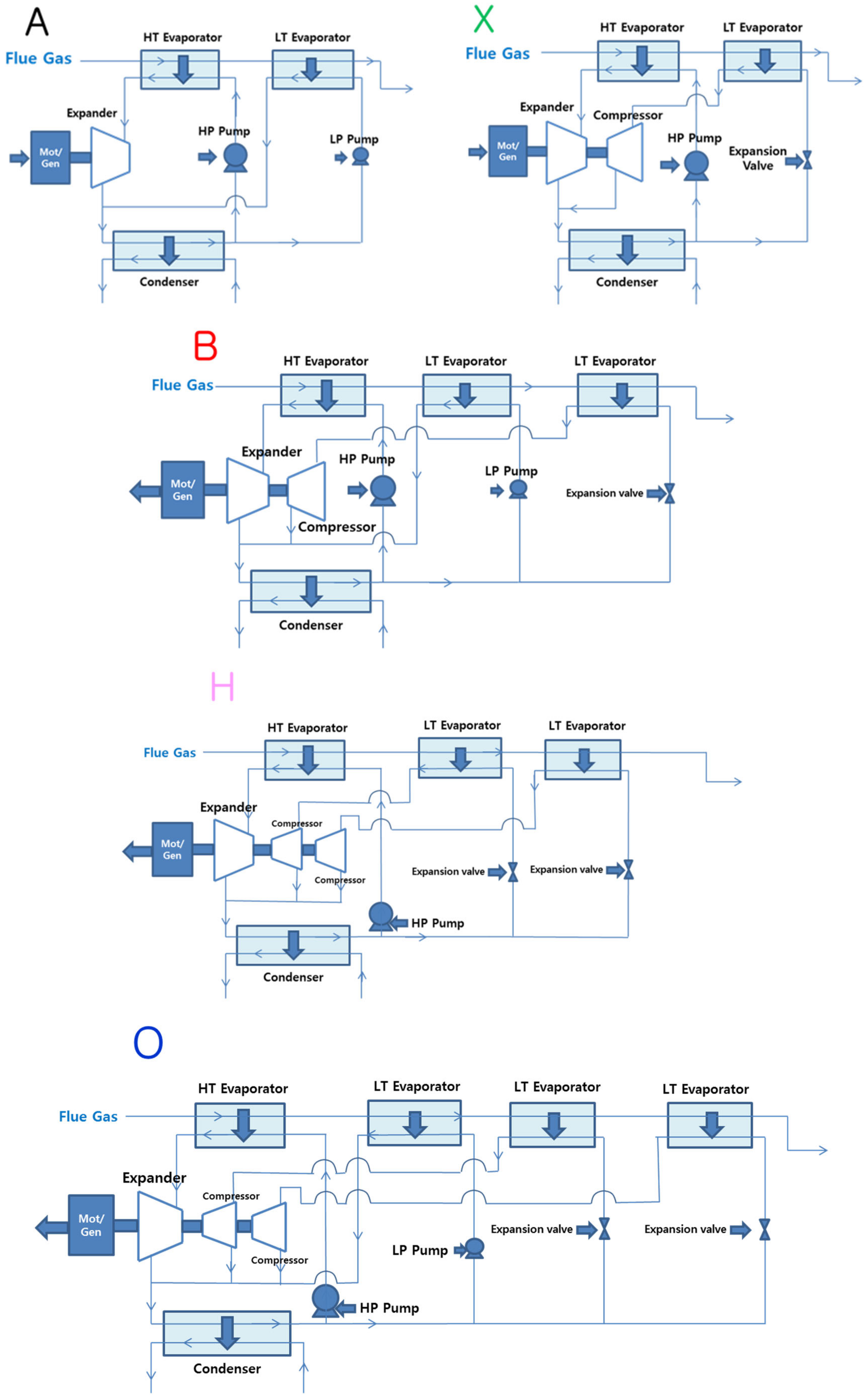
Figure 7 shows the five different configurations termed A, B, H, O, and X that can be implemented for the given ambient conditions. In addition to the ORC part, the water recovery system is generally comprised of a low-temperature evaporator (LT evaporator) in which heat transfer between low-temperature flue gas and the working fluid occurs for the sake of water recovery. After extracting heat at low pressure, the working fluid becomes vaporized and then passes into the common condenser to dissipate the heat.
Configuration A has an ORC system integrated into the pumped heat pipe cooling system; pumped heat pipe cooling (HPC) means only the use of a circulation pump for a phase change heat transfer. In this system, the evaporation temperature in the LT evaporator is equal to the condensation temperature of the condenser, neglecting the pressure drop. Therefore, the amount of cooling completed by the pumped heat pipe system is strictly restricted by the ambient temperature conditions. Configuration A is a two-stage system whereas configuration B is a three-stage system with the addition of a vapor compression cycle (VCC). Although a vapor compression cycle does not have any restrictions under ambient temperature conditions, it results in a loss of net power as the compressor is attached to the turbine. Configuration X had only a vapor compression cycle following the ORC system which had one large compressor. Configuration H has been considered to show the effect on power characteristics of the system if the large compressor work is distributed to various smaller compressors. In this particular case, two compressors have been used instead of one large compressor i.e. X, to signify the power consumption decrease caused by the low reversibility of two small compressors instead of a large one. Whereas configuration O has an additional HPC to reduce the power consumption further at the expense of an additional stage. The power output for the overall WHWRS (P
net) can be calculated as follows:
where P
HPC is the power required by the pumped HPC system and P
VCC is the power required by the vapor compression cooling system.
3. Results
The WHWRS was analyzed in two different manners in this study. First, the characteristics of the system were analyzed for constant water recovery yield and thereafter for constant ambient temperature conditions, providing power output behaviors and the effect that the range of ambient temperature and water recovery yield had on the capital cost in terms of system stages. In both of these approaches, the five schematics mentioned above that cover every possible case of cycle configuration within these temperature ranges were used.
3.1. Constant Water Recovery Yield
This section discusses the WHWRS characteristics relative to ambient temperature conditions. The objective was to attain 40 °C for the exhaust gas outlet temperature, which in turn provided approximately 50% water recovery efficiency. Configurations A, B, H, O, and X were analyzed for net power output, water recovery, and exhaust gas outlet temperature at ambient temperatures of 40, 30, and 20 °C. Note that this study tends to suggest optimization in terms of higher power output while keeping the system stages to a minimum while attaining the desired water recovery efficiency and flue gas temperature.
3.1.1. At 40 °C Ambient Temperature
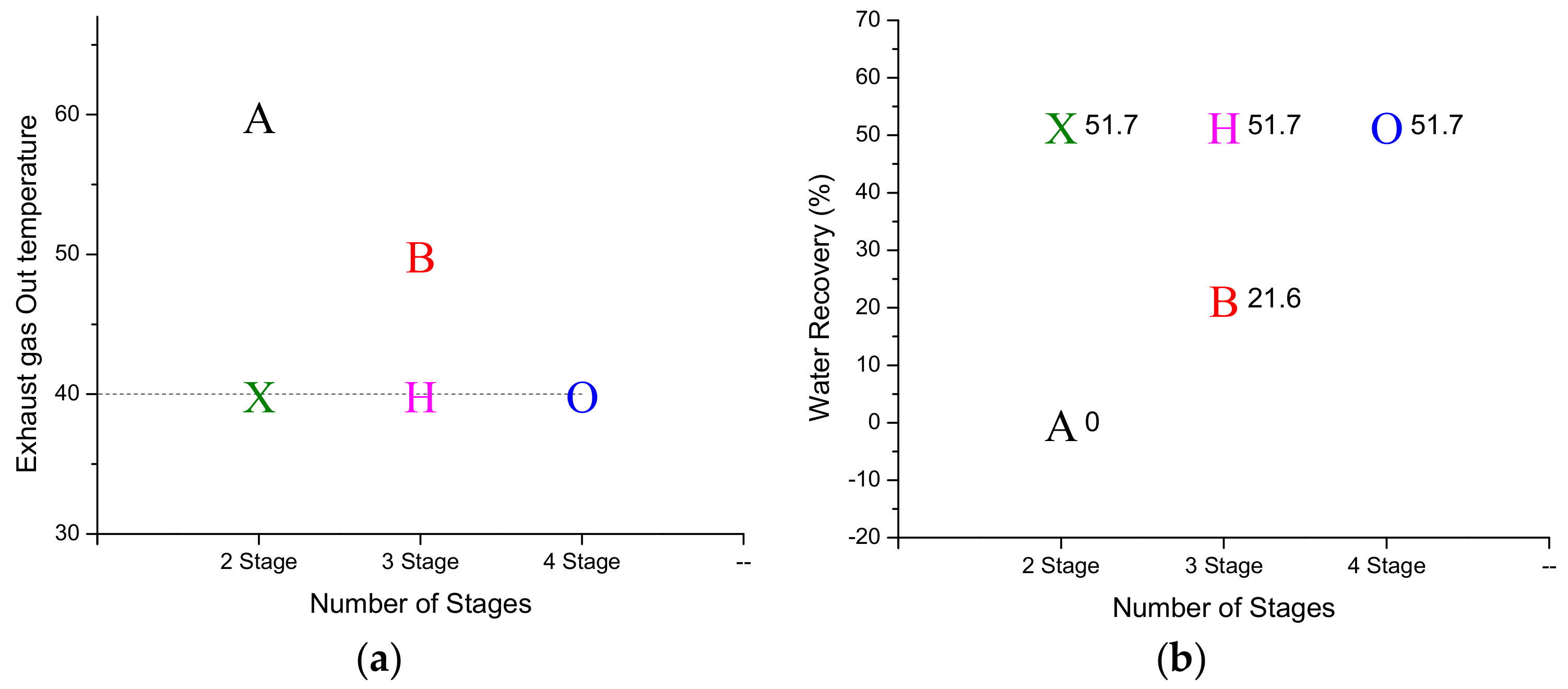
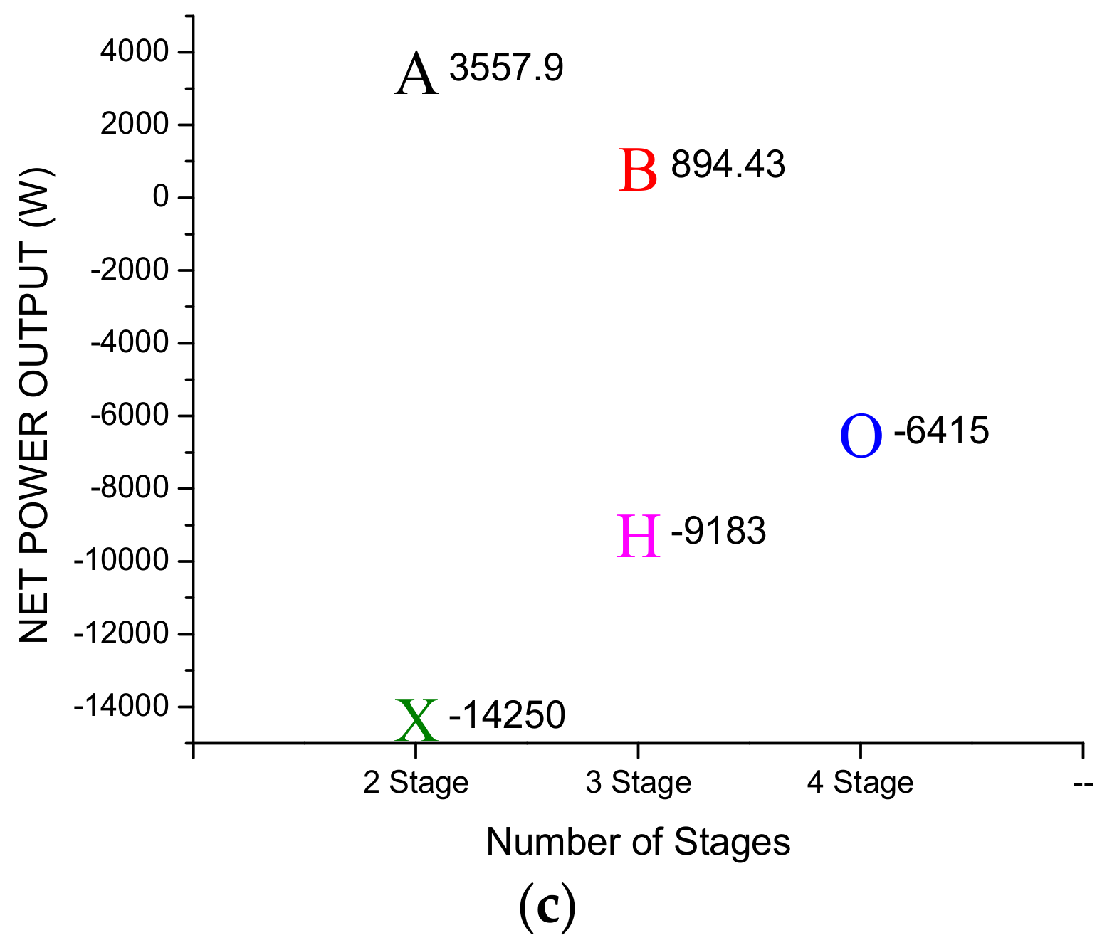
All five configurations can be seen in the graphs representing the properties of the system for the ambient condition of 40 °C as shown in
Figure 8a.
Figure 8a shows that three out of five configurations, i.e. X, H, and O, are those that fulfill the criteria of condensing the moisture present in the flue gas to the required temperature of 40 °C and achieving greater than 50% water recovery efficiency as shown in
Figure 8a,b at 40 °C ambient temperature conditions. Configurations A and B are only able to cool the flue gas to 60 °C and 50 °C and achieve 0 and 21.6% water recovery efficiency, respectively. The figure also shows that X is two-staged, whereas H and O are three- and four-stage systems, respectively, and able to achieve the desired results.
Figure 8c shows the power output distribution of all five configurations for the ambient temperature of 40 °C. Configuration X has the highest power consumption or power loss of all the configurations for this ambient temperature condition. In this case, no power output is produced by the system and the system power consumption is more than three times the power that is produced by configuration A, which is the highest power-producing configuration in the case of a 40 °C ambient temperature. O fulfills the criteria of water recovery and flue gas temperature, but despite being a four-stage system, it still consumes power for water recovery at this stage although much less than that required by X. Both B and H are three-staged systems, but only H is capable of attaining the desired results; however, its power consumption is higher than that of configuration O. Thus, at the ambient temperature of 40 °C, no configuration can obtain the desired results without the use of external power. In other words, at this point, the system can no longer be self-sufficient with the present configurations and cooling systems.
3.1.2. At 30 °C Ambient Temperature
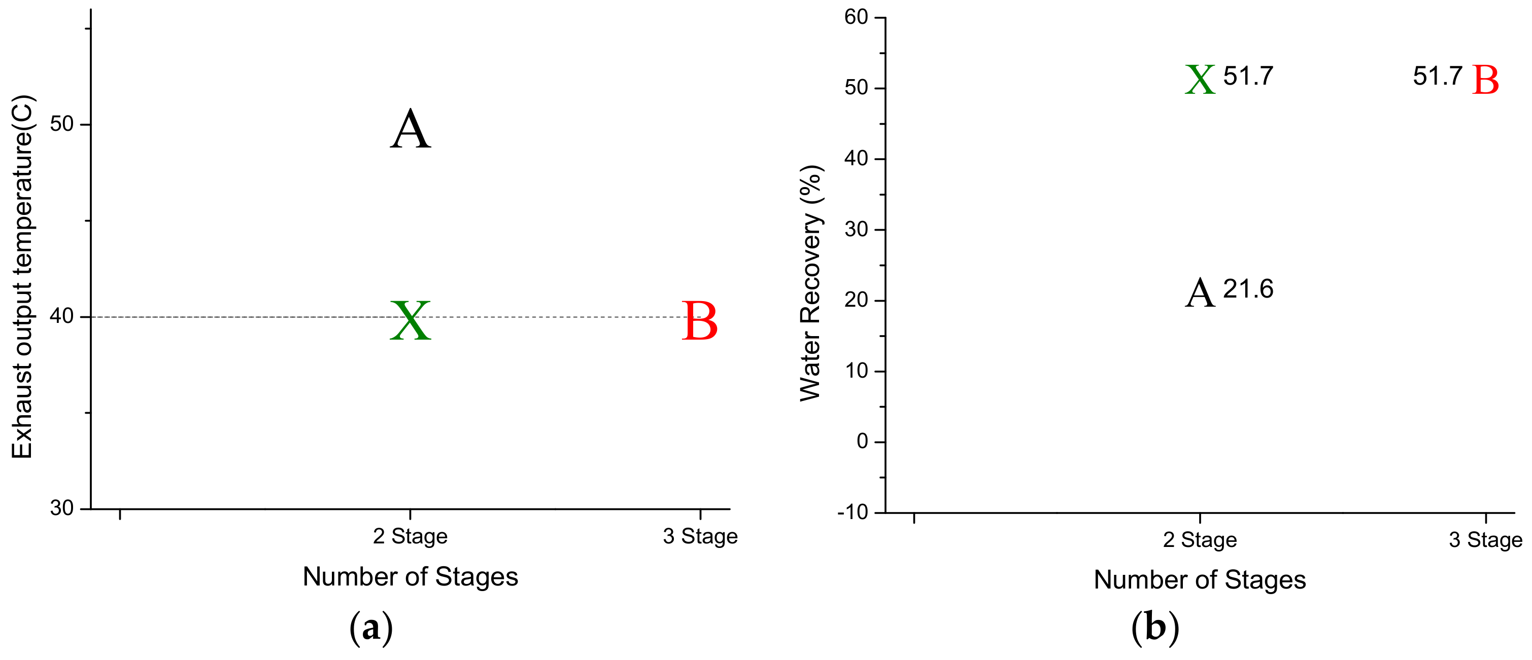
Figure 9 shows graphical representations of configurations feasible for an ambient temperature of 30 °C. Although A has the highest power output as compared to that of configurations B and X, it doesn’t cool the flue gas up to the desired temperature of 40 °C as shown in
Figure 9a; as a result it can recover only 21.6% of the water from the flue gas as shown in
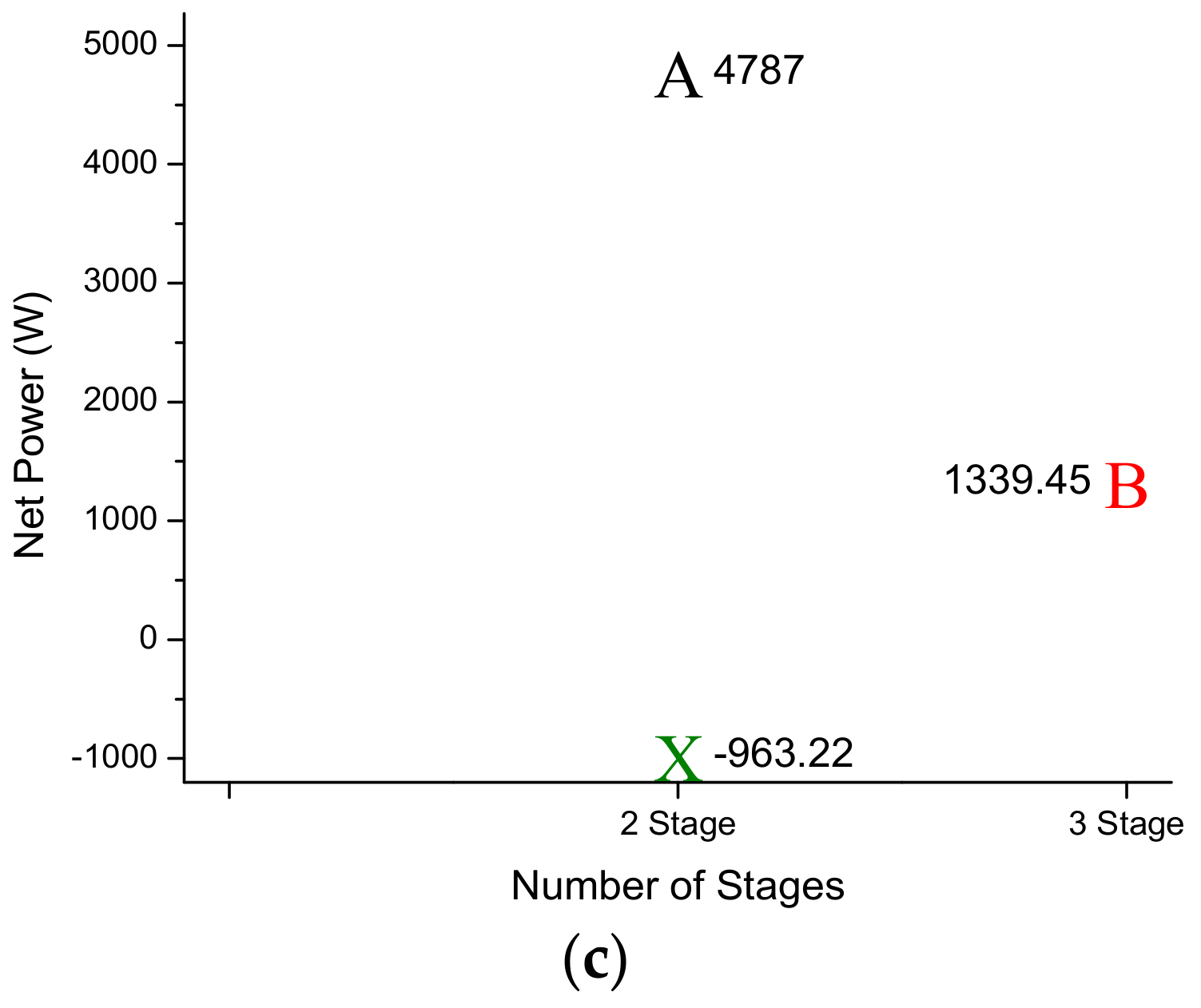
Figure 9b. The power output of B is higher than that of X as shown in
Figure 9c. Although, X is a two-stage cycle and B a three-stage cycle, both fulfilling the criteria of greater than 50% water recovery. However, B has an advantage over X of consuming relatively less power for its vapor compression cycle as 10 °C of decreased temperature was already obtained by the pumped HPC cycle. In contrast, configuration X has an advantage over B of having one less stage as it only utilizes the vapor compression cycle.
Note that O and H are the two configurations that were not considered for this ambient temperature condition case because they have no advantage and are not comparable. H has the same number of stages as B, so it has no advantage in terms of system stages. It also uses two stages of vapor compression whereas B uses one stage of heat pump cycle and one stage of vapor compression of the same capacity, so B has dominance over H in power consumptions as well, rendering the comparison meaningless. Similarly, O is essentially B with an additional stage. As the required output can be attained without the fourth stage with less power consumption, the comparison of the configuration with an additional stage, i.e. O, becomes absurd.
3.1.3. At 20 °C Ambient Temperature
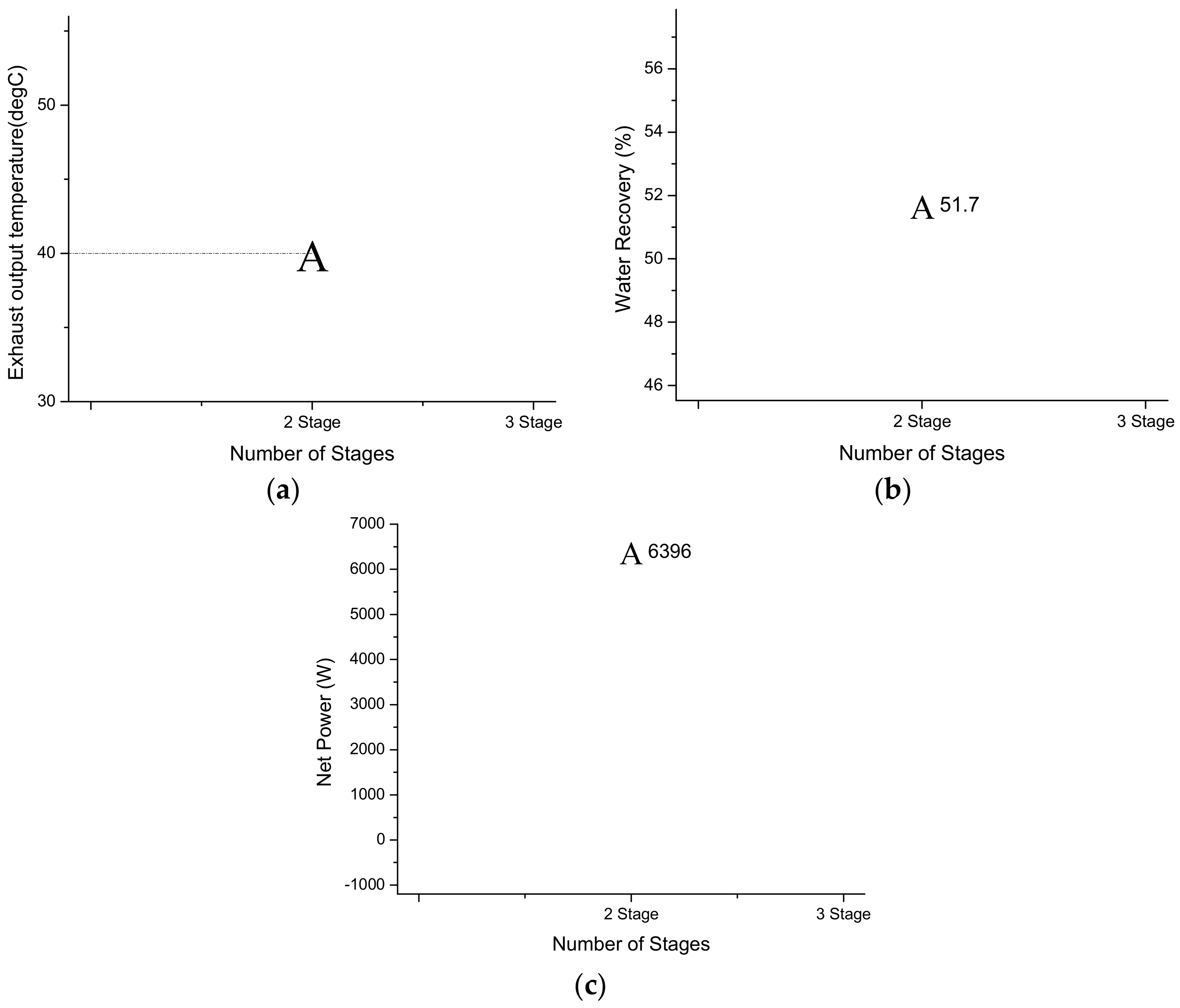
Figure 10a–c shows that configuration A is the only candidate selected from all five configurations that can achieve the desired water recovery efficiency at a flue gas outlet temperature of 40 °C at the highest power output with the least number of stages.
It eliminates all other configurations in terms of capital cost and power output desirability for the case of 20 °C. Although X is a two-stage configuration, for the fixed cooling temperature of flue gas to 40 °C, the vapor compression cycle in X results in a greater power loss than that of the pumped heat pipe cycle in A. Thus, X was not comparable to A for an ambient temperature of 20 °C in any way as it does not have any benefit over A and therefore was not considered. This is the most primary form of the WHWRS with the most benefits at hand at a generally common ambient temperature condition making A practically a desirable candidate for commercial purposes.
3.2. Constant Ambient Temperature
At the ambient condition of 20 °C, net power output, exhaust gas outlet temperature, and water recovery were analyzed relative to the increase in system stages. To avoid any confusion, only the configuration optimized for maximum power output for that particular stage was considered. For example, among all five configurations, A and X are both two-stage configurations, but instead of X, the characteristics representing a two-stage system in this section are for the A configuration because it shows a higher net power output compared to that of X. Similarly, between H and B, B will be considered for the three-stage system for the same reason, while O is the only candidate for the 4-stage configuration.
Figure 11 shows a graphical representation of the exhaust gas outlet temperature, water recovery, and net power output variation concerning the system stages that were optimized for maximum power output.
It can be seen that at the first stage there is no water recovery because at this stage only the ORC is being utilized for the 20 °C ambient temperature. The flue gas outlet temperature from the system is approximately 59 °C, which is higher than the dew point temperature of 55 °C of the moisture content present in the flue gas. However, the power output is the highest in this case relative to any other stage. The two-stage system has relatively less power output as it utilizes the pumped HPC system. Under a 20 °C ambient temperature condition, it can cool the flue gas below the dew point, down to 40 °C, increasing the water recovery efficiency from 0 to greater than 50% without a loss of a significant amount of power which it uses to operate the circulation pump of the pumped HPC system. The three-stage system represented utilizes a combination of a pumped HPC system and vapor compression cooling system because at a 20 °C ambient temperature and with our pinch point assumptions, a pumped HPC system cannot cool any further than 40 °C. Therefore, to further cool, we utilized the refrigeration cycle which as previously mentioned was restricted to create a temperature gradient of 10 °C in the flue gas to minimize the work required by the compressor. A four-stage system comprising one pumped heat pipe cycle and two vapor compression cycles collectively decreased the temperature of the flue gas to the ambient temperature of 20 °C, recovering greater than 80% of the water in the flue gas but at the cost of approximately 124 W of external power source in addition to turbine power output.
Condenser Characterization at Constant Temperature
There are multiple advantages of WHWRS in regions with inadequate water supply, including the capture of condensable particulate matter, minimizing of fresh water usage, and recovering water for potential needs within the power plant. In the case of water recovery units, whose objectives are to minimize pollution and fresh water usage, the condenser for the proposed WHWRS can be water-cooled. However, if the power plant is in a region with a low or declining water supply, the condenser should be cooled by forced air convection, either partially or totally without water cooling heat-exchangers. There is a certain amount of work input or net power loss that is required for the forced convection equipment, e.g., fan. Note that the previous calculations for all configurations have been made based on water-cooled condenser systems.
This section discusses the air-cooled condenser and compares its output with that of a water-cooled condenser, for the configurations showing maximum power output for their relative number of system stages at an ambient temperature of 20 °C. Using some design parameters for the organic Rankine cycle heat recovery power plant with a detailed analysis of the system [
30], the power consumption of the air-cooled condenser of the WHWRS was briefly estimated as follows. In the reference [
30], R134a was used as a working fluid, and the power consumption of the air-cooled condenser was 1224 kW to reject 58,912 kW of heat transfer rate to produce 5263 kW of net power with condensation temperature of 32.6 °C with a pinch point 6 °C at 18.8 °C ambient temperature. It was generally estimated that for fixed heat transfer rate, the lower the mass flow rate of air m
A more the rise in temperature of air T
rise as it passes through the condenser, i.e.,
The rise in air temperature for the reference case is 7.7 °C. Also, for a more mass flow rate of air, more fans, or a more powerful fan, is required, which means the mass flow rate of air is directly proportional to the power consumed by the air-cooled condenser Pacc.
When there is a higher heat transfer rate from the working fluid to the air-cooled condenser Q
acc, a higher power is required.
Our case closely resembles the one mentioned here [
30]. At the constant ambient condition of 20 °C, the working fluid is at 30 °C in the condenser. For the pinch point of 5 °C, the rise in temperature and the heat transfer rate of the reference case and our case can be compared to determine the power consumption of the air-cooled condenser.
Table 3 shows heat transfers and power consumption of all one to four stages of configuration, optimized for maximum power output by comparing the proportional quantities with the reference case. It can be clearly seen that for a fixed ambient temperature condition, there is a small net power difference between stage 1 and stage 2 for the water-cooled condenser system. Even though the heat rejection is same, the power required by the air-cooled condenser to compensate a large amount of latent heat from the flue gas absorbed by the working fluid makes a huge gap between stage 1 and stage 2 with an air-cooled condenser in comparison to the water-cooled condenser. Generally, the power consumption of an air-cooled condenser seems to increase with the increase in the number of stages of the system.
4. Economic Analysis
Although a detailed economic analysis is beyond the scope of this work, a simple estimation of the potential cost of the system could be helpful to evaluate its usefulness. An economic model of the ORC system presented by Usman et al. [
31] was used to estimate the cost of the WHWRS. In the case of a previous two-stage WHWRS represented by configuration A, applied to a 600 MW coal-fired power plant with condensation temperature of 30 °C at 20 °C ambient temperature, the component cost of the ORC unit and pumped HPC unit are presented in
Table 4 and
Table 5, respectively. The cost of cooling fans for the air-cooled system is estimated using correlations in [
32].
The economic benefit of water recovery was estimated as follows based on Jeong et al. [
33]. Here, the assumed 16% volume of water vapor in flue gas is equivalent to 10% weight of water vapor. With 50% of water recovery efficiency, the potential annual fresh water recovery is:
- ⧫
750 kg/s × 10% × 50%/1000 m3/kg × 3600 s/hr × 24 h × 365 days × 95% (annual availability) = 1,123,470 m3
- ⧫
Assuming a water cost of
$1.69 per cubic meter [
31], an annual savings of water recovery is
$1,998,594
The water withdrawal in a subcritical 600 MW power plant consists of 2381 L/MWh of cooling water make-up, 400 L/MWh of FGD make-up, and 36 L/MWh of boiler make-up [
34], which can be partially covered by 225 L/MWh of regenerated water as condensate out of 450 L/M of moisture in flue gas in this study.
The economic benefit of heat recovery of an ORC unit was estimated as follows, based on Walraven et al. [
32], assuming the price obtained per MWh of produced electricity of
$67.5/MWe, an annual availability of 95%, and the cost of operation and maintenance of 2.5% of the investment cost of the ORC and pumped HPC per year. The potential net annual income through heat recovery for the water cooled plant is:
- ⧫
6369 kW (net power) × 24 hrs × 365 days × 95% (availability) = 53,003 MWe
- ⧫
53,003 MWe × $67.5/MWe – 2.5% × ($9,171,798 + $8,674,810) = $3,131,470
Whereas for the air-cooled plant,
- ⧫
3928 kW (net power) × 24 hrs × 365 days × 95% (availability) = 32,689 MWe
- ⧫
32,689 MWe × $67.5/MWe – 2.5% × ($6,799,528 + $5,089,581) = $1,909,280
To utilize the recovered water, the condensed water usually needs further treatment such as filtration, acid removal, or demineralization [
33]. The cost of water treatment could be included in a detailed economic analysis.
In addition to the economic benefits of the electric power and water recovery, the WHWRS can contribute to reduce the condensable particulate matter [
27] and to decrease the humidity around the power plant, which decreases diffusion of pollutants and promotes secondary particulate matter formations. These environmental benefits were not included in the economic analysis. Furthermore, the waste heat from the condenser of the WHWRS could be utilized as a heat source for the a heat pump used for deep-cooling of the coal-fired power plant flue gas [
35].
5. Discussion
This study discussed the design of a WHWRS using a single working fluid. It also analyzed various problematic scenarios of increased capital cost and power consumption, presented in practical situations by a change in the ambient temperature caused by a change in climate conditions depending on the season and location of a power plant. Thus showing that relative to a change in ambient condition, the performance of a WHWRS will vary. As this study suggests, a heat recovery ORC is to be optimized for maximum power output because the auxiliary components of a water recovery system such as a pump or compressors as well as cooling system consume power. Thus, the system must be optimized for maximum power output for it to be as self-sufficient as possible at an increased ambient temperature condition. Optimizing the high-pressure side concerning commercially available components is a reasonable approach. Superheating of the working fluid slightly above the saturation temperature is better for the longevity of the turbine.
A pumped HPC system has low power consumption as it only uses a circulation pump, but the amount of gradient it creates in temperature of the flue gas strictly depends on the ambient temperature conditions. However, for a 20 °C ambient temperature, configuration A, for a minor decrease in power output has an abrupt increase from 0% to 50% in water recovery efficiency. Contrary to that, the vapor compression cycle has no limitation regarding ambient temperature. However, the larger the gradient it creates in the flue gas, the greater the work done by the compressor, eventually resulting in more power consumption. As shown in some cases, the power consumption to run the system exceeds the turbine power output thus external power is required. In case of 30 °C ambient temperature condition, to achieve a similar target system alters from being self-sufficient to power dependent by the difference of only one stage i.e., B having one additional stage is self-sufficient in power output whereas X is dependent on external power source although the power generated by ORC cycle is the same for both the configurations. Thus, it is always feasible to use pumped heat pipe cooling before vapor compression if the number of stages or compactness of the system is not a priority. Combination of both pumped heat pipe and vapor compression allows some of the temperature to be decreased in the flue gas by the pumped heat pipe cycle, which can reduce the work done by the compressor of the vapor compression cycle. The work of one large compressor can also be reduced by distributing the work to smaller compressors, which is beneficial in terms of power consumption because they create less irreversibility resulting into less loss as can be seen in the case of configuration H which consumes less power than X. The capital cost, however, increases as the number of stages increase because of the additional components required for additional vapor compression cycles.
The results shown by configuration A have promising potential for practical applications at regions with moderate climate conditions, i.e. 20 °C to 25 °C or lower. For regions with higher temperature climates, i.e., 40 °C through different season cycles, recovering an adequate proportion of water from the flue gas with the dew point of the moisture in the flue gas being 50 °C to 55 °C, is only possible with the presence of vapor compression cycle in the system. Therefore, all the rest of the configurations show the variation in the trade-off between power output and the number of stages, with several modifications, with ORC and VCC being the essential parts of the system. Thus, for regions with higher ambient temperatures, it depends on desirability for either higher power output or lesser number of stages. Based on the requirements, the designer can decide if either vapor compression cycle (X) is enough for the heat and water recovery according to the requirements or integration of pumped heat pipe with vapor compression cycle (B) is feasible. Distribution of a large compression work (H) into several compressors is required, or both the integration of pumped heat pipe and the distribution of the compressor work (O) fulfills his requirements of power generation while maintaining the capital cost. Also, water cooled, partially water-cooled, or air-cooled condensation has to be selected based on the availability of water. Note that, regardless of the configuration selected, the system will have better water and power yields for all ambient temperatures less than the ambient temperature at which the system is designed. As the ambient temperature becomes less and less than the design ambient temperature, the yields will increase further. Therefore, it is recommended that the system must be designed for the highest average ambient temperature condition of the region where the system is to installed.
The economic benefit may seem to tend to decrease with the increase in the number of stages, but the greater number of stages will serve the purpose of greater water recovery efficiency at lower temperatures than the design temperature. Therefore, being designed for peak temperature around the year, the system with a larger number of stages will tend to have a greater economic benefit as it will be able to recover more water and heat at the lower temperatures.
Other than the water being used for the primary purposes of cooling and condensing hazardous gases, water recovery itself reduces the incidence of white plumes and smog around the power plant, since the high humidity flue gas prevents pollutant diffusion, which promotes secondary air pollutant transformation, and contributes to smog.
In order to utilize the system for a specific site with the given objective functions and constraints, the system can be optimized by taking account of more factors related to electrical power distribution systems presented by Nguyen et al. [
11] and Duong et al. [
10].


