Article

Optimizing the Grouting Design for Groundwater Inrush Control in Completely Weathered Granite Tunnel: An Experimental and Field Investigation

1
Jiangxi Vocational and Technical College of Communication, Nanchang 330000, China
2
Jiangxi Road and Port Engineering Bureau, Nanchang 330000, Jiangxi, China
3
Quanzhou Institute of Equipment Manufacturing, Haixi Institutes, Chinese Academy of Sciences, Quanzhou 362000, China
4
Guangxi Computing Center Co., Ltd., Nanning 530022, China
5
Department of Civil and Environmental Engineering, Faculty of Science and Technology, University of Macau, Macao 999078, China
*
Author to whom correspondence should be addressed.
Sustainability 2019, 11(13), 3636; https://doi.org/10.3390/su11133636
Submission received: 15 April 2019 / Revised: 15 June 2019 / Accepted: 18 June 2019 / Published: 2 July 2019
(This article belongs to the Special Issue Sustainable Water Resources Management for Disaster Risk Reduction)

Abstract

:
Groundwater and mud inrush disaster from completely weathered granite presents a huge difficulty for tunnel construction, which requires the grouting measurement with favorable performance. To propose the optimal material parameters for grouting, numerous tests, including strength, permeability, and anti-washout, were conducted to evaluate the effects of grouting filling ratio (GFR), curing age and water velocity on the grouting effect. The test results show that: (1) The hydraulic property of completely weathered granite can be significantly improved by increasing the grouting volume and curing age. In particular, when GFR ≥ 48%, the cohesion and internal friction angle increased to about 200 kPa and 30°, which were more than three and ten times of that pre-grouting. (2) With the increase of GFR, the permeability exhibited three stages: Slowly decreasing stage, sharply decreasing stage and stable stage. When increased from 32% to 48%, the permeability coefficient sharply decreased two orders of magnitude, namely from 4.05 × 10⁻⁵ cm/s to 1 × 10⁻⁷ cm/s. (3) The particle erosion rate decreased sharply to below 10% in the low water velocity (v ≤ 0.2 m/s) when GFR ≥ 48%, but still exceeded 50% when v ≥ 0.4m/s. The results indicated that the grouting volume of GFR = 48% was a suitable grouting parameter to reinforce the completely weathered granite, particularly in the low water velocity condition. The field investigation of hydraulic-mechanical behaviors in the Junchang tunnel indicated that the grouting effect can be improved markedly.

1. Introduction

Tunnel constructing in completely weathered granite often faces the serious risk of groundwater and mud inrush [1,2,3], which presents a great difficulty for engineers. As the common treatment measure, grouting technology is far from the anticipated effect in rich-water conditions, especially in flowing water environments due to water erosion [4,5,6,7]. In this condition, the slurry is prone to be diluted and scoured, leading to the deterioration of water plugging and the ground reinforcement effect [8,9]. Therefore, the grouting design with the advanced performance of strength, permeability and anti-washout has become a key issue for the geotechnical engineers, which was strongly demanded in practical engineering [10,11].
The main factors of grouting design include material used, grouting control and grouting parameters [12,13]. The material used is the primary factor to prevent water and mud inrush disasters, which must be determined according to the hydrogeological conditions. In general, the favorable groutability of the used materials were desired in permeation grouting in order to penetrate the grout into the ground [13,14,15]. Furthermore, for the unfavorable geological environment, i.e., the dynamic water environment, the special slurry properties, i.e., the anti-dispersion properties, are crucial to the prevention of water inrush disasters [8]. Therefore, under rich-water completely weathered granite ground, the superfine cement cannot permeate into the ground due to its fine particle size, as demonstrated in Xiamen Xiang’an subsea tunnel [16] and Hong Kong’s mass transit railway [17]. In addition, special grouts such as chemical grouts and polyurethane grouts possess potential advantages with anti-dispersion properties, which should be considered in dynamic water environments [11,18].
The grouting control main includes grouting pressure and grouting spread. In general, high grouting pressure can induce great grouting spread distance, but may also result in the damage to structures and the deformation of formation [19]. Therefore, a new method, namely grout intensity number (GIN), was developed to control grouting operation, which aimed to ensure that the high grouting pressure could inject the desired volume without damages to the structures [20]. However, this method was limited to use due to the difficulties in determining the grout spread and distinguishing the fractures state [21]. In order to obtain real- time control over the grouting spread, another new grouting control method was developed for permeation grouting by Still et al. [22,23], which had already been used in Swedish projects successfully. Nevertheless, in completely weathered granite ground, the grouting spread is dominated by fracture grouting, which is significantly different with permeation grouting, indicating that those methods were limited in completely weathered granite due to groutability.
Finally, the grouting parameters, particularly the grouting volume, are the foundation of the grouting design [24]. The conception of the grouting volume is to follow the method of filling ratio of porous by slurry from the permeation grouting. The previous designed methods to obtain the filling ratio were mainly relying on the experimental investigation of permeation grouting and the engineering experience [25,26]. In general, the higher filling ratio governs the better grouting reinforce effect. For sandy soil, Cui and Cui presented the filling ratio of 50–70% for medium and coarse sand, and 70–100% for gravel sand according to the permeation grouting theory [26]. Differently, the grouting filling ratio of 30–50% obtained from the field engineering was recommended for clay soil [26]. However, due to the difference of grouting mechanism in completely weathered granite and the special dynamic water environment, the above grouting volume may not fit for this formation and its appropriate grouting filling ratio should be studied in the future.
The objective of this study is to investigate the influence of grouting volume on the reinforcement effects in completely weathered granite in the rich-water environment and propose the appropriate grouting volume. First, a series of tests, including strength, permeability and anti-washout under different grouting filling ratios, curing ages and water flow rates, were conducted. Then the modifications of completely weathered granite at pre- and post-grouting were systematically analyzed and quantitatively evaluated. Accordingly, a referenced grouting volume was proposed from the experimental studies and was examined by the field test in Junchang tunnel in China.

2. Materials and Design

2.1. Test Materials

2.1.1. Cement

The rapid hardening sulphoaluminate cement used in this study (type R. SAC.42.5 in accordance with the standard GB20472-2006 of China) was from Huaxin Cement Plant Factory (Huangshi, P.R. China). According to the grouting ratio commonly used in grouting engineering, the water-cement ratio (W/C) of the grout was set as 0.8. The initial setting time and compressive strength at 3 d of the cement were 21 min and 42.5 MPa respectively.

2.1.2. Completely Weathered Granite

The completely weathered granite was taken from the Junchang Tunnel [13]. Tests by X-Ray Diffraction (XRD) analysis indicated that the minerals of the completely weathered granite were quartz particle, illite, and kaolinite with a mass proportion of 75.2%, 19.3%, and 5.5%, respectively. The basic physical and mechanical properties are shown in Table 1.

2.1.3. The grouting Sample of Completely Weathered Granite

The grouting filling ratio (GFR) is a key index to design the grouting volume, which is defined as follows:
G F R = Q V n ( 1 + β )
where Q is the grouting volume, V is the volume of grouting ground, n is the soil porosity which was 0.36 in the test, β is the grouting loss rate which was 10% in the test according to the experience.
In the test, grouting filling ratios with 0%, 16%, 32%, 48%, 64%, 80% were designed to evaluate the influence of grouting volume on the grouting effect.
For the strength and permeability tests, the grouting samples were prepared by mixing the grout with the designed GFR into the completely weathered granite, according to the standard JGJ/T 233-2011 of China. Afterwards, the materials were mixed uniformity. The cylinder specimens for triaxial test and permeability tests were made with a size of Φ 39.1 mm × 80 mm (diameter × height) and Φ 61.8 mm × 40 mm. For the anti-washout test, specimens with a cubic size of 40 × 40 × 40 mm3 were prepared by a self-developed grouting test device [27], as shown in Figure 1. The specimens were cured under standard conditions (20 °C ± 2, RH > 90%) for designated ages of 3 d, 7 d before testing.

2.2. Test Procedure and Scheme

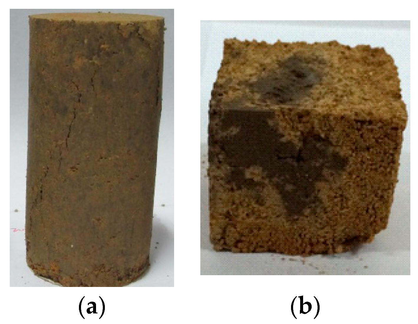
2.2.1. Strength Test

Using the triaxial shear test, the strength characteristics of completely weathered granite pre- and post-grouting were investigated by the undrained unconsolidated triaxial method. The confining pressure was 200 kPa, 400 kPa, 600 kPa and 800 kPa, respectively, in general, but it was changed to 100 kPa, 200 kPa, 300 kPa, 400 kPa for the sample with the high grouting fill ratio (≥48%) considering the sample strength was relatively high.

2.2.2. Permeability Test

The variable head permeability test method was used to determine the permeability coefficient of the sample after grouting.

2.2.3. Anti-Washout Test

In order to evaluate the anti-washout properties of grouting samples, a self-design testing device was developed, which is shown in Figure 2 [27]. The device consisted of a sink, flow valve, water tank, and particles collection equipment. The length, width, and height of the sink were 200, 10, and 10 cm, respectively. The flow valve was designed to adjust the water flow velocity. Three water velocities, including 0.2, 0.4, 0.6 m/s, were designed in the anti-washout tests.
The detail anti-washout test procedure was illustrated as follows. First, the initial grouting sample with mass M0 was placed into the sink under the designed water velocity. Then, the particle erosion amount was recorded at 10 s, 30 s, 60 s, 90 s, 120 s and following an interval of 60 s. When the particle erosion amount between two records was less than 0.1 g, namely, the particles were not eroded, the water inlet was closed. The total particle erosion amount can be collected from the collection system and the eroded mass M1 was recorded. Thus, the anti-washout properties can be evaluated by the index of PER (particle erosion ratio), which is defined by the ratio of M1/M0.

3. Test Results and Analysis

3.1. Strength Test

3.1.1. Stress-Strain Characteristics

Figure 3 shows the stress-strain curves with different GFRs at a 7 d curing time. With an increasing GFR, the peak strength increased. In addition, the pattern of stress-strain curve changed with the increasing GFR. When the GFR was smaller than 48%, as shown in Figure 3a,b, the sample exhibited the pattern of strain hardening. However, when the GFR was higher than 48%, the stress-strain curve was gradually transformed into the pattern of strain softening, as shown in Figure 3c–e. This indicates that the failure model of completely weathered granite after grouting changed from plastic to brittle properties, and the strain localization occurred in the failure process under the action of shear stress.

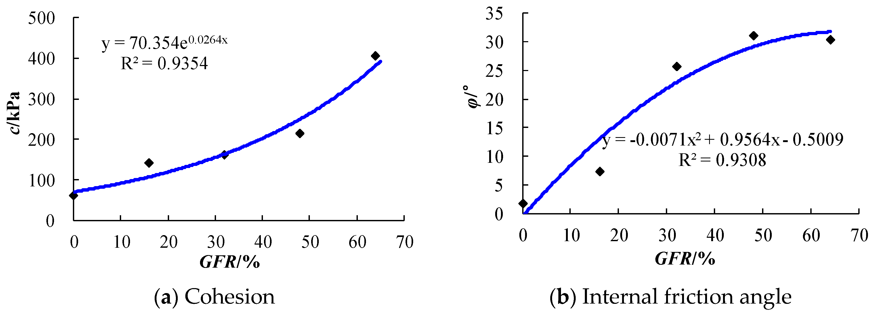
3.1.2. Strength Characteristics

According to the Mohr–Coulomb criterion, the strength parameters (cohesion c and internal friction angle φ) can be calculated from the above strength tests, which are listed in Table 2. At the same curing time, with the increase of GFR, the cohesion increased exponentially, and the internal friction angle increased generally and then kept stable, as shown in Figure 4. In particular, when the GFR reached 48%, the cohesion increased to about 200 kPa which was more than three times of that without grouting, and the internal friction angle reached up to the maximum which was more than 30°. Furthermore, the strength parameters increased in general with the increase of curing time.

3.1.3. Scanning Electron Microscopy (SEM) Characterization

To analyze the mechanism of strength evolution characteristic after grouting, the scanning electron microscopy (SEM) analysis for different GFRs was carried out [27]. The test results are displayed in Figure 5.
For the sample with a small GFR, i.e., 16% and 32%, the structure was loosened and contained many large pores, as shown in Figure 5a,b. In addition, few cement hydration products were formed in the sample, especially when GFR = 16%, which indicated that the strength could be increased slightly. However, with the increase of GFR, numerous pores were filled by cement particles and the structure seems to be more dense, as shown in Figure 5c,d. In addition, a large amount of cement hydration products, i.e., calcium silicate hydrates (CSH) and ettringite crystals (AFt) were formed in the completely weathered granite, which can improve the strength of completely weathered granite significantly.

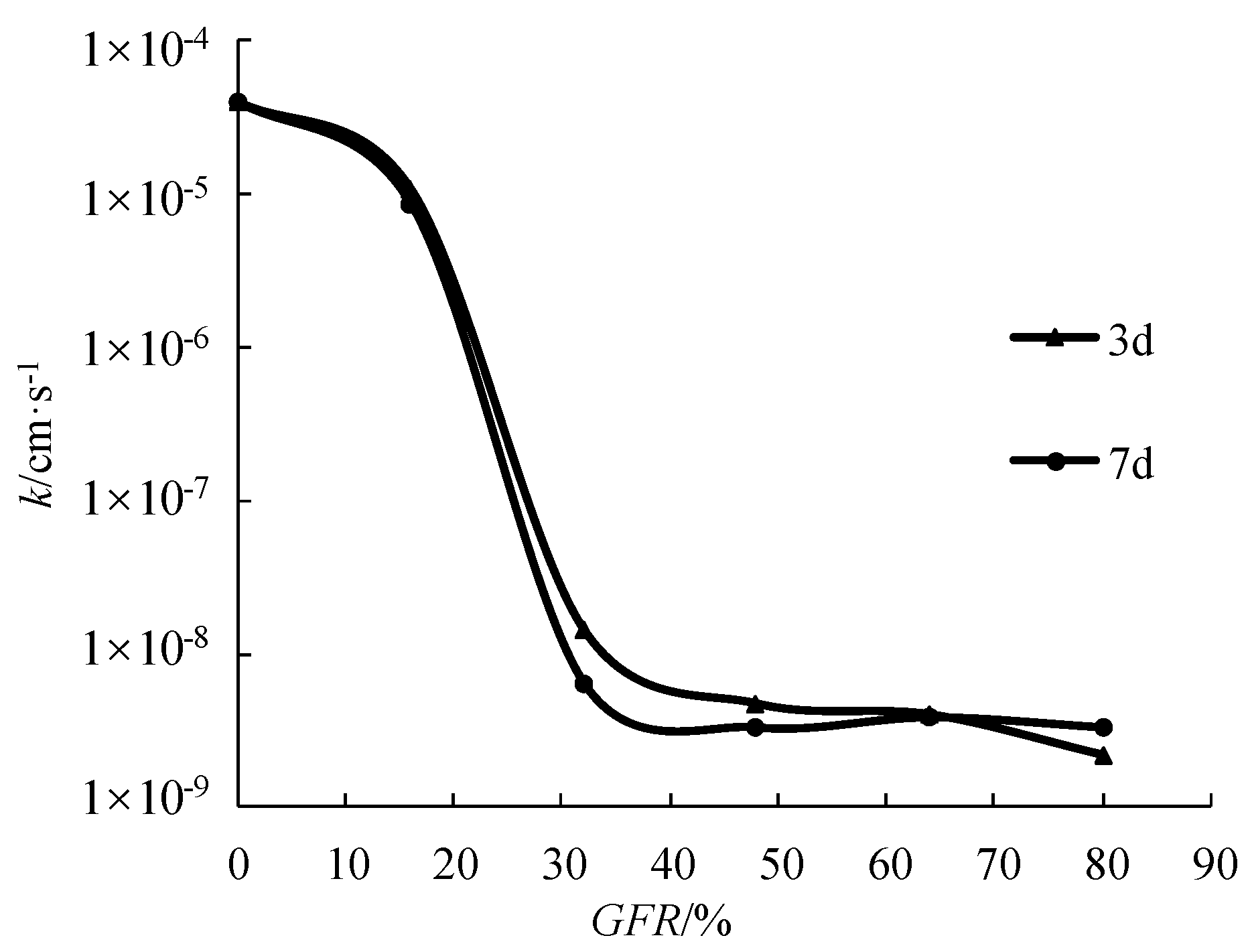
3.2. Permeability Test

Figure 6 shows the permeability coefficient results and indicates that the permeability coefficient under different GFR exhibited three evolution stages: Slowly decreasing stage, sharply decreasing stage and stable stage. For the sample without grouting, the permeability coefficient was 4.05 × 10⁻⁵ cm/s. With the GFR increased to 16%, the permeability coefficient decreased slowly to 8.6 × 10⁻⁶ cm/s. In contrast, when GFR exceeded 32%, the permeability coefficient decreased sharply from the order of 10−5 cm/s to 10−8 cm/s. However, when GFR exceeded 48%, the permeability coefficient changed by a few.
The main reasons that the permeability coefficient could be decreased with the increase of the GFR were analyzed as follows. First, from a physical perspective, the addition of grout could fill the pores of the sample, which can decrease the porosity, thereby reducing the connectivity of the pores and increasing the tortuosity of the seepage process, and finally, decreasing the internal permeability of the sample. Secondly, from the chemical perspective, the cement hydration products underwent a series of physical and chemical reactions with the particles and water to enhance the cementing ability, which reduced the permeability coefficient of the sample.

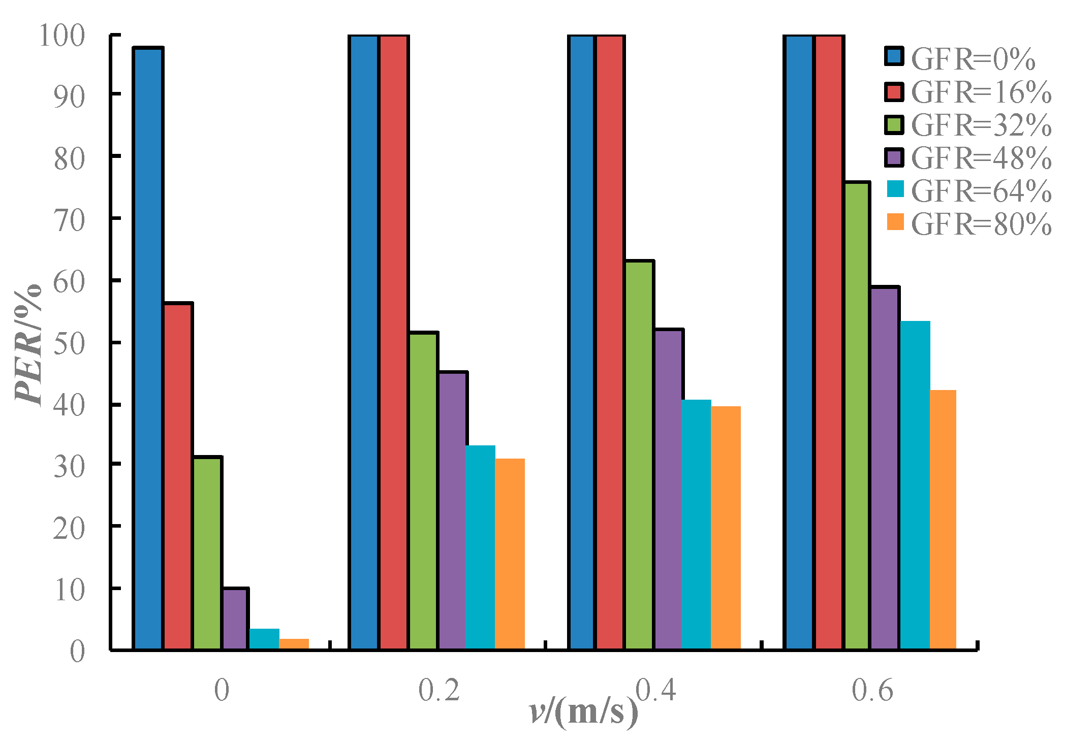
3.3. Anti-Washout Test

A comprehensive test method was used to investigate the anti-washout performance of completely weathered granite after grouting. The test results are shown in Table 3 and Figure 7.
It can be observed that the PER decreased significantly with the increasing GFR and decreasing water flow rate. Under the hydrostatic condition (v = 0 m/s), the PER decreased to below 10% when GFR ≥ 48%, indicating that anti-washout performance could be satisfied after the GFR increased to more than 48%. When the water velocity increased to 0.2 m/s, the PER of most of the samples was lower than 50%, with the minimum being lower than 35%. This indicates that the anti-washout performance and PER could be significantly modified by adjusting the grouting volume when the velocity was small. However, with the water velocity further increased to more than 0.4 m/s, the PER of most of the samples exceeded 50%. This indicates that the anti-washout performance cannot be significantly modified by merely increasing grouting volume when the velocity was very high. During this condition, the modified cement slurries or chemical slurries with favorable anti-washout performance were suggested to decrease the velocity primarily, then the Portland cement with the suggested GFR could be used to reinforce the ground.
In general, the higher filling ratios govern the better grouting reinforce effect. However, considering the economic cost and construction efficiency, an appropriate grouting volume should be proposed. Based on the above analysis of strength, permeability and anti-washout performance, it can be obtained that in completely weathered granite, GFR = 48–64% is the suitable grouting parameter range. The result is similar in the medium and coarse sand grouting (namely GFR = 50–70%), but is significantly different in the gravel sand grouting (namely GFR = 70–100%) according to the permeation grouting theory, as presented by Cui and Cui [27]. However, it should be noted that grouting in completely weathered granite is significantly different with that in sandy soil, especially in terms of the grouting diffusion mechanism. The results from permeation grouting theory cannot be used in regards to the completely weathered granite. In addition, Cui and Cui [27] summarized the grouting filling ratio of 30–50% for clay soil from the field investigation. This indicates that the grouting filling ratio for different ground materials may differ and, thus, they should be determined according to the details of the hydrogeological condition.

4. Field Investigation of Grouting Reinforcement Effect—A Case Study

The Junchang tunnel is a part of a major project at Cenxi highway in Guangxi province, China. Due to the unfavorable geological conditions, the tunnel suffered serious water and mud inrush disasters, and curtain grouting was thus adopted to overcome the difficulties. To verify the effectiveness of the developed grouting volume, field investigations of curtain grouting were conducted in the Junchang tunnel.

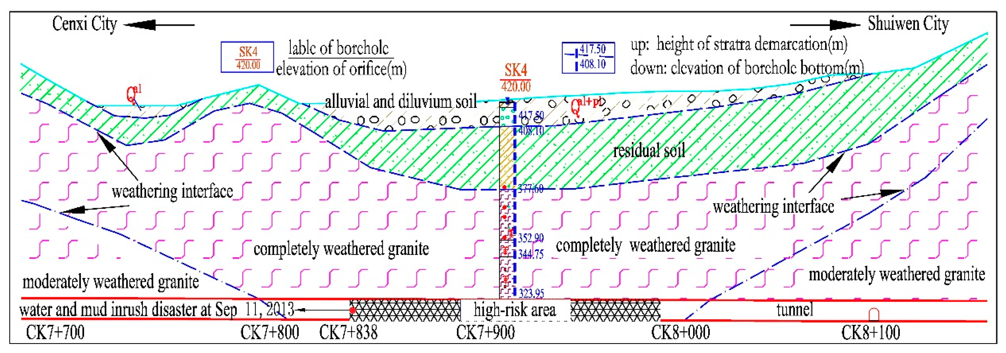
4.1. Ground Conditions and Geological Disasters

The ground conditions were evaluated according to the geological prospecting and geophysical prospecting, as illustrated in Figure 8. The lithology throughout the tunnel was weathered granite with different grades. In particular, from CK7+838.5 to CK7+981.6, the area is a large rich-water, with completely weathered granite region, which is makes for a high-risk region. Tunnel construction in these regions has suffered four large-scale waters and mud inrush disasters from 11 September 2013 to 23 October 2015, as shown in Figure 9. The largest water inflow volume exceeded 250,000 m3, which resulted in the severe property damage and hindered the construction seriously [13].

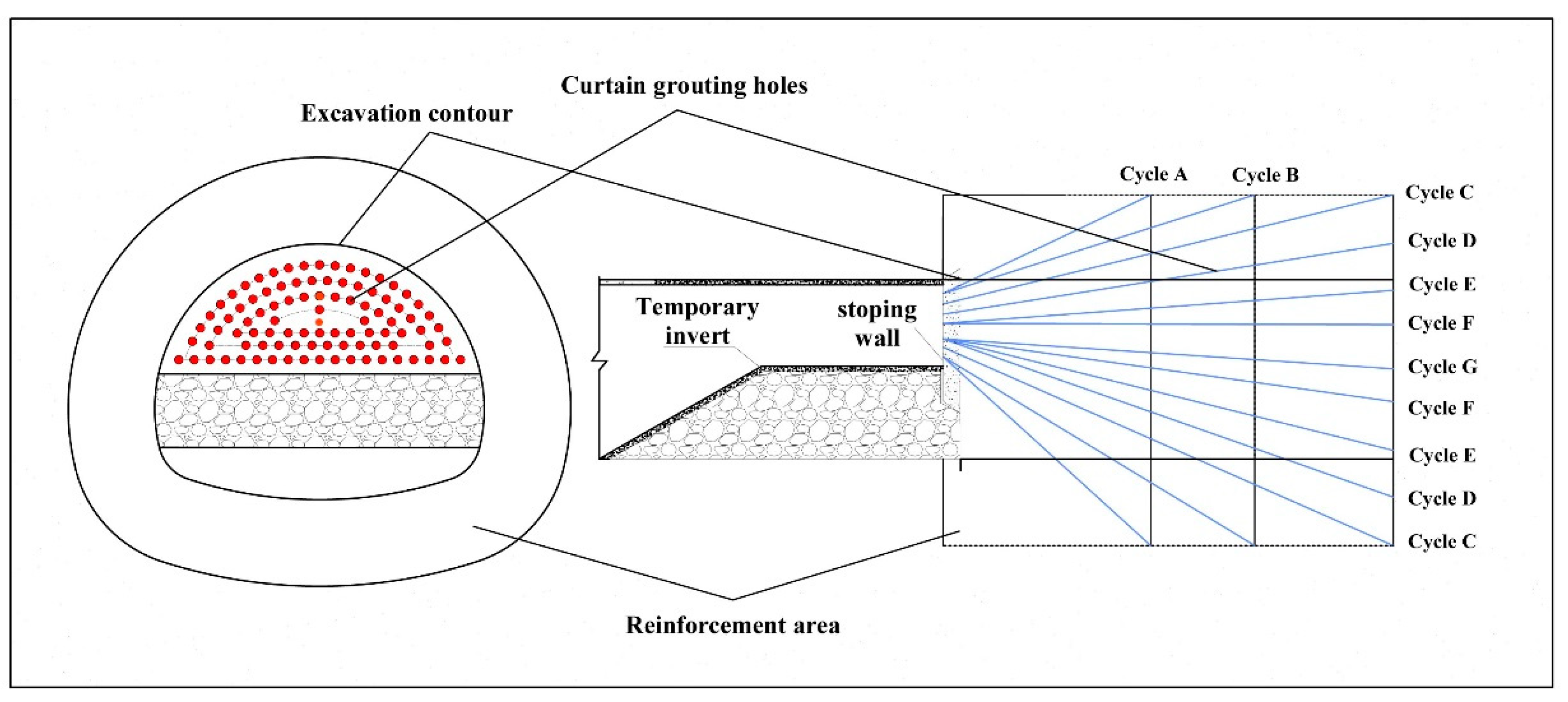
4.2. Grouting Design

The main grouting parameters in the Junchang tunnel were designed according to the following specifications:
(1)
As shown in Figure 10 and Figure 11, 95 grouting holes including 7 cycles (A–G) from outside to inside were designed. In addition, the construction process for the curtain grouting was conducted from cycle A to cycle G.
(2)
The designed grouting volume was 48 m3/m according to the above tests.
(3)
The curtain grouting thickness of 5–8 m was adopted based on the numerical results [13]. The grouting reinforced length was 15 m, 20 m, or 25 m, depending on the geological conditions.
(4)
Considering that the grouting spread pattern in completely weathered granite was mainly fractured grouting, the grouting pressure was required to reach the initiation pressure of the ground. In addition, the buried depth of this high-risk zone is approximately 96 m. Thus, the designed maximum grouting pressure was 4–6 MPa.
(5)
Considering the factors of anti-washout performance, strength performance and economics, several grouting materials including the cement slurry, cement-sodium silicate slurry and cement-GT slurry were adopted to use in different hydraulic conditions [13].
(6)
The grouting effect was examined by examination holes, P-Q-t curve, and excavation [16,28].

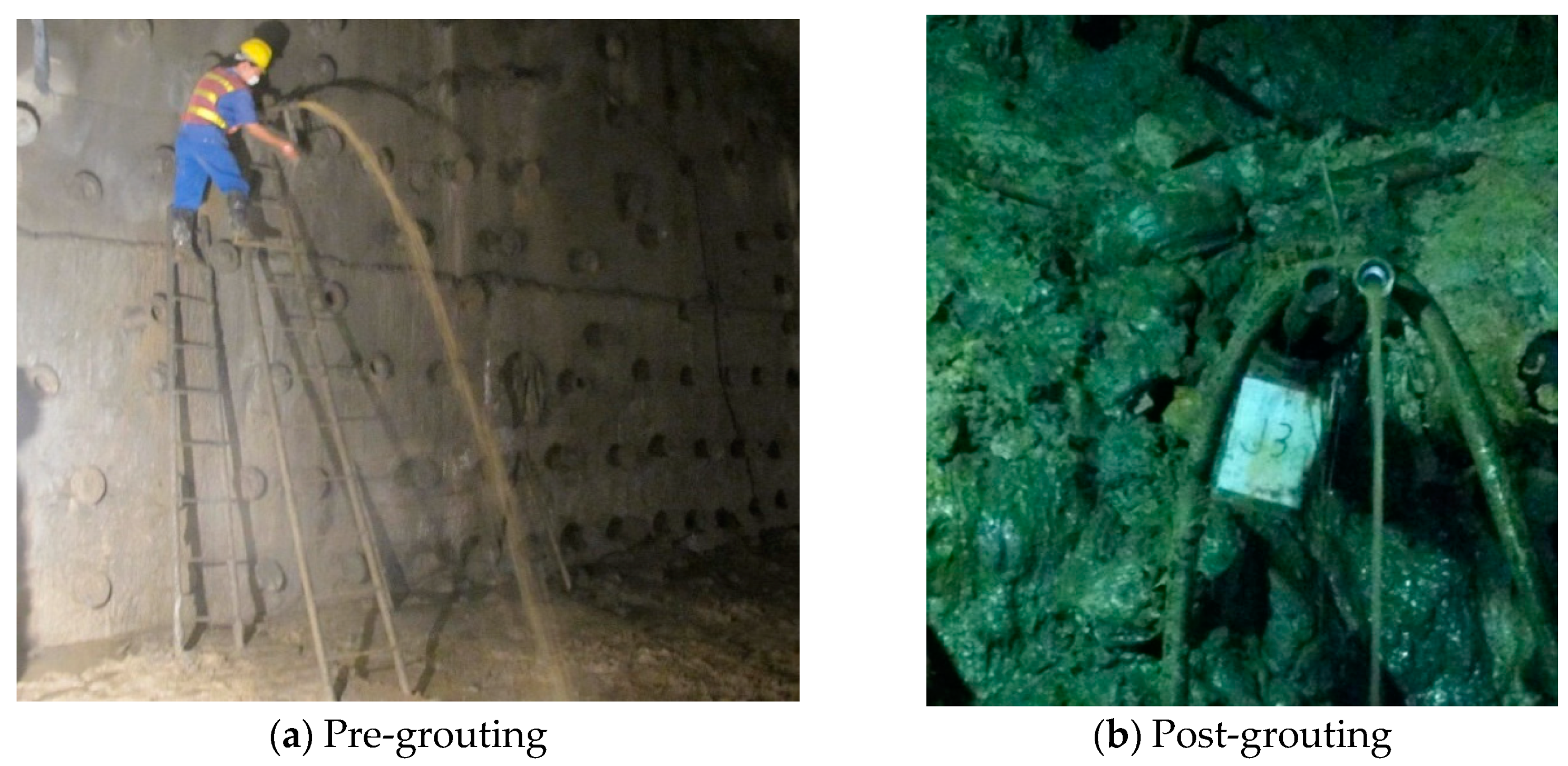
4.3. Grouting Effects Examination

In order to evaluate the grouting reinforcement effect, the grouting cycle zone (DK7+952~DK7+932) was taken as an example. In this grouting cycle, seven examination holes were designed to investigate the hydraulic and mechanical behavior of the ground after a curtain grouting, which are shown in Table 4 and Figure 12. The detailed information exposed by examination holes is shown in Table 5.
It can be seen from the Table 5 that the hole-making rates after grouting were all more than 90%, which indicated that there was no serious collapse in the holes and the ground had been reinforced well. Furthermore, Table 5 shows that water inflows were less than 5 L/min, and the minimum water inflow was merely 1.2 L/min, as shown in Figure 13a. According to the field investigation, the water inflows exposed before grouting were about 50 L/min, as shown in Figure 13b. This indicates that the water inflows have decreased by more than 90% after grouting. In addition, the initial 15 m for the examination holes were dry, and it was merely at the last few meters that some water appeared. This means that the water has been driven away and the surrounding rock has possessed favorable water plugging behavior.
In order to evaluate the strength, compactness and the geosphere integrity of the ground, the grouting tests in the examination holes were carried out. The key parameters in grouting tests, namely P (injection pressure)-Q (injection velocity)-t (time) curves were recorded. Figure 14 shows the typical P-Q-t curves of J-2.
For grouting in completely weathered granite, the ground was generally reinforced by composed grouting patterns, including the filling, permeating, compaction and splitting grouting. First, the grout was injected by way of filling and permeating, and the grouting pressure was relatively low due to the high porosity of ground. Therefore, a great deal of grout was demanded to fill the pores or fractures, showing the high injection velocity in this stage. Then, when the pores or fractures were entirely filled, the higher grouting pressure was demanded to surmount the minimum principal stress of the ground [16]. At this stage, the grouting patterns were mainly compaction and splitting grouting, and the grouting pressure increased significantly, and the grouting velocity decreased sharply.
Figure 14 displays that the grouting pressure quickly increased to 8 MPa, and the grouting velocity sharply declined to 5 L/min in 6 min indicating that unfavorable geology was reinforced by the grouting. This can be explained as follows: The pores or fractures in the ground has been filled, and the ground compactness and strength were improved significantly during the curtain grouting, so that the grouting pressure increased rapidly and the grout could not be pumped largely into the ground.
Based on the above investigation, the hydraulic and mechanical performance of the ground was improved notably and satisfied by the excavation environment. As shown in Figure 15, the tunnel face was dry and the medium was reinforced by lots of grout veins. The excavation demonstrated that the grouting parameters proposed above were reliable.

5. Conclusions

In order to propose the suitable grouting parameters for field engineering, considering the factors of grouting volume (GFR), curing age and water velocity, numerous tests including strength, permeability and anti-washout were conducted to evaluate the grouting reinforcement effect of completely weathered granite. The main conclusions drawn are as follows:
(1)
The completely weathered granite could be effectively reinforced by grouting. In addition, with the increase of grouting filling ratio and curing time, the physical and mechanical properties can be improved significantly. In particular, when the GFR increased to 48%, the cohesion and internal friction angle increased to about 200 kPa and 30°, which were more than three and ten times of that without grouting. Simultaneously, the permeability coefficient decreased two orders of magnitude, namely from 4.05 × 10⁻⁵ cm/s to 1 × 10⁻⁷ cm/s, and the PER decreased sharply to below 10% in the lower water flow rate. The results demonstrate that the completely weathered granite was reinforced well after the grouting with GFR ≥ 48%.
(2)
In the high-water velocity condition, the grouting effect decreased sharply. In particular, when the velocity increased to more than 0.4 m/s, the anti-washout performance after grouting with Portland cement was extremely deficient, which the PER exceeded 50%. The results indicate that in the high-water velocity condition, the composite slurries or measurements should be taken, i.e., the chemical slurry was primarily used to control the water velocity, and the Portland cement was then used to reinforce the ground.
(3)
According to the experimental studies, the GFR of 48% was proposed as an appropriate grouting parameter in completely weathered granite. This suggested value was demonstrated to be reasonable, effective and reliable by field investigations in the Junchang tunnel.

Author Contributions

Conceptualization, J.L.; Methodology, W.Z. and J.L.; Formal Analysis, D.W., K.L. and G.L.; Investigation, W.Z., D.W., K.L. and L.Q.; Data Curation, J.L. and G.L.; Writing-Original Draft Preparation, W.Z., J.L. and G.L..; Writing-Review & Editing, J.L., G.L. and K.L..; Supervision, J.L.; Project Administration, J.L.; Funding Acquisition, J.L.

Funding

This research was funded by the National Natural Science Foundation of China [grant number 51809253], and the Natural Science Foundation of Fujian Province, China [grant number 2019J01142].

Conflicts of Interest

The authors declare that they have no conflicts of interest.

Data Availability

The data used to support the findings of this study are available from the corresponding author upon request.

References

  1. Zhao, Y.; Li, P.; Tian, S. Prevention and treatment technologies of railway tunnel water inrush and mud gushing in China. J. Rock Mech. Geotech. Eng. 2013, 5, 468–477. [Google Scholar] [CrossRef] [Green Version]
  2. Liu, J.; Chen, W.; Yang, D.; Yuan, J.; Li, X.; Zhang, Q. Nonlinear seepage–erosion coupled water inrush model for completely weathered granite. Mar. Georesour. Geotechnol. 2018, 36, 484–493. [Google Scholar] [CrossRef]
  3. Liu, J.; Chen, W.; Liu, T.; Yu, J.; Dong, J.; Nie, W. Effects of Initial Porosity and Water Pressure on Seepage-Erosion Properties of Water Inrush in Completely Weathered Granite. Geofluids 2018, 2018. [Google Scholar] [CrossRef]
  4. Davis, G.M.; Horswill, P. Groundwater control and stability in an excavation in Magnesian Limestone near Sunderland, NE England. Eng. Geol. 2002, 66, 1–18. [Google Scholar] [CrossRef]
  5. Sadeghiyeh, S.M.; Hashemi, M.; Ajalloeian, R. Comparison of permeability and groutability of ostur dam site rock mass for grout curtain design. Rock Mech. Rock Eng. 2013, 46, 341–357. [Google Scholar] [CrossRef]
  6. Høien, A.H.; Nilsen, B. Rock mass grouting in the Løren tunnel: Case study with the main focus on the groutability and feasibility of drill parameter interpretation. Rock Mech. Rock Eng. 2014, 47, 967–983. [Google Scholar] [CrossRef]
  7. Barani, H.R.R.; Khatib, M.M. Back analysis of grout treatment at Sumbar Dam using the joint hydraulic factor. Rock Mech. Rock Eng. 2015, 48, 2485–2488. [Google Scholar] [CrossRef]
  8. Liu, J.; Chen, W.; Nie, W.; Yuan, J.; Dong, J. Experimental research on the mass transfer and flow properties of water inrush in completely weathered granite under different particle size distributions. Rock Mech. Rock Eng. 2019, 52, 2141–2153. [Google Scholar] [CrossRef]
  9. Liu, J.; Li, X.; Saffari, P.; Liang, Q.; Li, L.; Chen, W. Developing a Polypropylene Fabric, Silica Fume, and Redispersible Emulsion Powder Cementitious Composite for Dynamic Water Environment. Polymers 2019, 11, 47. [Google Scholar] [CrossRef]
  10. Foyo, A.; Tomillo, C.; Maycotte, J.I.; Willis, P. Geological features, permeability and groutability characteristics of the Zimapan Dam foundation, Hidalgo State, Mexico. Eng. Geol. 1997, 46, 157–174. [Google Scholar] [CrossRef]
  11. Li, X.F.; Sun, J.T.; Chen, W.Z.; Yuan, J.Q.; Liu, J.Q.; Zhang, Q.Y. Strength and anti-washout property of fibre silica fume cement grout. Rock Soil Mech. 2018, 39, 3157–3164. [Google Scholar]
  12. Zhong, D.H.; Yan, F.G.; Li, M.C.; Huang, C.X.; Fan, K.; Tang, J.F. A real-time analysis and feedback system for quality control of Dam foundation grouting engineering. Rock Mech. Rock Eng. 2015, 48, 1947–1968. [Google Scholar] [CrossRef]
  13. Liu, J.; Chen, W.; Yuan, J.; Li, C.; Zhang, Q.; Li, X. Groundwater control and curtain grouting for tunnel construction in completely weathered granite. Bull. Eng. Geol. Environ. 2018, 77, 515–531. [Google Scholar] [CrossRef]
  14. Akbulut, S.; Saglamer, A. Estimating the groutability of granular soils: A new approach. Tunn. Undergr. Space Technol. Inc. Trenchless Technol. Res. 2002, 17, 371–380. [Google Scholar] [CrossRef]
  15. Azimian, A.; Ajalloeian, R. Permeability and groutability appraisal of the Nargesi Dam site in Iran based on the secondary permeability index, joint hydraulic aperture and lugeon tests. Bull. Eng. Geol. Environ. 2015, 74, 845–859. [Google Scholar] [CrossRef]
  16. Zhang, D.L.; Fang, Q.; Lou, H.C. Grouting techniques for the unfavorable geological conditions of Xiang’an subsea tunnel in China. J. Rock Mech. Geotech. Eng. 2014, 6, 438–446. [Google Scholar] [CrossRef]
  17. Bruce, D.A.; Shirlaw, J.N. Grouting of Completely Weathered Granite with Special Reference to the Construction of the Hong Kong Mass Transit Railway. Available online: www.geosystemsbruce.com/v20/biblio/1985_groutingWeatheredGranite.pdf (accessed on 1 July 2019).
  18. Li, S.C.; Liu, R.T.; Zhang, Q.S.; Zhang, X. Protection against water or mud inrush in tunnels by grouting: A review. J. Rock Mech. Geotech. Eng. 2016, 8, 753–766. [Google Scholar] [CrossRef] [Green Version]
  19. Engineers, U.A. Grouting Methods and Equipment. Unified Facilities Criteria (UFC 3-220-06). Available online: https://www.wbdg.org/ffc/dod/unified-facilities-criteria-ufc/ufc-3-220-06 (accessed on 1 July 2019).
  20. Lombardi, G.; Deere, D. Grouting design and control using the GIN principle. Int. Water Power Dam Construct. 1993, 45, 15–22. [Google Scholar]
  21. Rafi, J.Y.; Stille, H. Applicability of using GIN method, by considering theoretical approach of grouting design. Geotech. Geol. Eng. 2015, 33, 1431–1448. [Google Scholar] [CrossRef]
  22. Stille, B.; Stille, H.; Gustafson, G.; Kobayashi, S. Experience with the real time grouting control method. Geomech. Tunn. 2009, 2, 447–459. [Google Scholar]
  23. Stille, H.; Gustafson, G.; Hassler, L. Application of new theories and technology for grouting of dams and foundations on rock. Geotech. Geol. Eng. 2012, 30, 603–624. [Google Scholar] [CrossRef]
  24. Nonveiller. Grouting Theory and Practice; Elsevier Science Publishers: New York, NY, USA, 1989. [Google Scholar]
  25. Zhang, M.Q.; Peng, F. Grouting Technology in Underground Engineering; Geological Publishing House: Beijing, China, 2008. [Google Scholar]
  26. Cui, J.J.; Cui, X.Q. Grouting Technology in Tunneling and Underground Engineering; China Architectural Press: Beijing, China, 2011. [Google Scholar]
  27. Liu, J.; Chen, W.; Yuan, J. Test on anti-scouring property of grouting reinforced body in completely weathered granite. Chin. J. Rock Mech. Eng. 2016, 35, 1767–1775. [Google Scholar]
  28. Wang, Q.; Qu, L.Q.; Guo, H.Y.; Wang, Q.S. Grouting reinforcement technique of Qingdao Jiaozhou Bay subsea tunnel. Chin. J. Rock Mech. Eng. 2011, 30, 790–802. [Google Scholar]
Figure 1. Test specimens for strength and anti-washout tests. (a) Cylinder specimen for the strength test; (b) cubic specimen for the anti-washout test.
Sustainability 11 03636 g001
Figure 2. Anti-washout test device.
Sustainability 11 03636 g002
Figure 3. Deviatoric stress and axial strain curve in different grouting filling ratios at age = 7 d.
Sustainability 11 03636 g003
Figure 4. Cohesion and internal friction angle results under different grouting filling ratios (GFRs) at 7 d curing time.
Sustainability 11 03636 g004
Figure 5. Scanning electron microscopy (SEM) results for different grouting filling ratio.
Sustainability 11 03636 g005
Figure 6. Permeability test results for different grouting filling ratios.
Sustainability 11 03636 g006
Figure 7. PER results under different water velocities at 7 d curing time.
Sustainability 11 03636 g007
Figure 8. Geological profile of the Junchang tunnel.
Sustainability 11 03636 g008
Figure 9. Water and mud inrush accidents in the Junchang tunnel.
Sustainability 11 03636 g009
Figure 10. Curtain grouting design.
Sustainability 11 03636 g010
Figure 11. Construction of curtain grouting in DK7+952.
Sustainability 11 03636 g011
Figure 12. Layout of examination holes.
Sustainability 11 03636 g012
Figure 13. Water inflow pre- and post-grouting in DK7+952.
Sustainability 11 03636 g013
Figure 14. P-Q-t curves.
Sustainability 11 03636 g014
Figure 15. Grouting effect exposed by excavation in DK7+948.
Sustainability 11 03636 g015
Table 1. Physical and mechanical properties of completely weathered granite.
Natural Density (g·cm−3)Natural Moisture (%)Cohesion cuu (kPa)Internal Friction Angle Φuu (°)Proportion of Different Particle Size Groups/%
<0.0075 mm0.0075 mm–2 mm2–10 mm>10 mm
1.91760.21.930.857.010.861.34
Table 2. Results of triaxial compression test.
LabelGFR (%)Curing Time (d)c (kPa)φ (°)
G-00-60.41.9
G16-3 *163142.55.1
G32-3323178.823.1
G48-3483199.730.0
G64-3643400.127.9
G16-7167149.67.3
G32-7327160.925.7
G48-7487213.531.0
G64-7647404.330.3
* G16-3 indicates that the specimen at grouting filling ratios (GFRs) and curing time = 3 d.
Table 3. Anti-washout results.
Nov (m·s−1)AgePER/%
GFR = 0% *GFR = 16%GFR = 32%GFR = 48%GFR = 64%GFR = 80%
10397.856.231.59.83.51.5
207-54.830.69.33.41.3
30.2310010052.442.739.732.8
40.2710051.445.232.931.0
50.4310068.853.151.045.6
60.4710063.051.840.339.7
70.6310072.259.555.048.8
80.67d10075.758.753.442.0
* For the test in GFR = 0%, the results in different curing age were almost the same. The results in high velocity were significantly greater than with low velocity (0.2 m/s), which indicates that the particle erosion ratio (PER) will be 100% for the other higher velocity.
Table 4. Design parameters of examination holes.
LabelCoordinate of Opening HoleCoordinate of Final HoleDeclination (°)Vertical Angle (°)Depth of Drilling Hole (m)
X0 (cm)Y0 (cm)X (cm)Y (cm)
J-10 078 453 2.2 12.8 20.5
J-2222 −112705 100 13.6 6.0 20.7
J-3130 −405384 −676 7.2 −7.7 20.3
J-4−377 −392−707 −676 −9.4 −8.1 20.5
J-5−560 −676−1186 −254 −17.4 11.9 21.4
J-6−311 0 −638 353 −9.3 10.0 20.6
J-7−239 −149 595 −239 22.6 −2.6 21.7
Table 5. Results of the examination holes.
LabelDepth of Drilling (m)Depth of Hole-Making (m) 1Hole-Making Rate (%) 2Water Inflow (L/min)Location of Water Inflow (m)
J-118.517.0921.217
J-217.817.5984.117
J-319.018.0954.616
J-418.017.6984.416
J-518.518.0974.515
J-618.017.0941.716
J-718.017.5973.616
Notes: 1. Depth of hole-making is length where no significant collapse occur, namely the stability drilling length. 2. The hole-making rate is defined as the ratio of the hole-making depth divided by drilling depth.

