Methodology of Temperature Monitoring in the Process of CNC Machining of Solid Wood


1
Faculty of Wood Sciences and Technology, Technical University, 96053 Zvolen, Slovakia
2
National Forest Centre, Forest Research Institute, 96053 Zvolen, Slovakia
*
Author to whom correspondence should be addressed.
Sustainability 2019, 11(1), 95; https://doi.org/10.3390/su11010095
Submission received: 1 December 2018
/
Revised: 11 December 2018
/
Accepted: 21 December 2018
/
Published: 24 December 2018
(This article belongs to the Special Issue Sustainability in Wood Science)
Abstract
:The issue of the change in tool temperature as a result of the machining process is presented in this paper. The aim of the paper is to put forward a proposal and subsequently to verify the methodology of temperature monitoring in the process of computer numerical control (CNC) machining in real time. Subsequently, the data can be used in the process of adaptive machine-tool control. Experiments were used to determine whether the research method is appropriate. Oak, beech and spruce wood turning blanks with the thickness of 20 mm were machined using a 5-axis CNC machining centre. A temperature change observation resulting from the changes in parameters of the removed layer was used to test whether the research method is relevant. Parameters of the removed layer were affected by the changes in feed rate in the range from 1 ÷ 5 m·min−1 in the removed layer (1–5 mm) or in wood species used in the experiment. As emerges from the proposed methodology, it is possible to monitor the changes in tool temperature responding to minimal changes in technological parameters on a relatively small size of a milled surface quite accurately. Sensitivity to given changes in technological parameters as well as the importance of the methodology was proven.
1. Introduction
Wood processing into a final product is a very complex technological process. Milling is one of the wood-machining methods. The main aim of milling is to create a workpiece with the requested shape, dimensions and surface quality [1,2]. For productive, effective and economically viable milling it is important to fully understand the milling [3,4,5,6,7]. The quality of the milled surface is affected by various factors. They can be defined as the cutting conditions [8,9,10,11,12]. During the process of milling, the surface quality is affected in particular by the tool used [13]. In the case of wear, an increase in vibration frequency can occur. Subsequently, a decrease in the quality of the milled surface is observed. Vibration can be reduced by a lower feed rate; however, it affects the quality of machining as well. The tool wear is affected by many factors including workpiece material, cutting parameters, geometry and material of the tool, temperature of the tool and cooling methods. All of these parameters influence the tool life [14,15,16].
Temperature at which the tool is used is one of the essential parameters affecting the tool life. Cutting and milling are processes associated with energy loss. Part of the mechanical energy consumed during cutting and milling is changed into thermal energy due to friction. The thermal conductivity of wood is low, unlike metals [17,18,19,20]. Therefore, most of the heat generated during milling is transferred to the tool that results in its increased temperature. The tool life, surface quality (high operating temperature can cause surface defects or its burning) as well as the process safety (danger of chip ignition) can be affected by temperature. Understanding the origin and distribution of tool temperature is a key step in resolving this issue.
The effect of tool temperature during the process of cutting on the tool life was studied by many authors. Some of them dealt with the issue experimentally, others analytically or numerically e.g., [21,22,23,24,25,26]. They found out that the tool temperature is affected by various parameters “of the cutting process” including the tool material, tool quality, tool wear, type of milling cutter used, thickness of the removed layer, feed rate, cutting speed, direction of milling [27,28,29], wedge angle and sharpening angle [30]. Tool temperature is affected, besides other things, by the material machined and its anatomical properties (e.g., wood species, grain direction, wood defects), physical properties (moisture content―in some cases the temperature increases with the increase in moisture content, in other cases it decreases, density) and mechanical properties (strength, hardness etc.) [31,32,33].
When the tool temperature increases, a gradual decrease in strength, hardness and chemical stability of the tool material” can be observed. Moreover, “the abrasion resistance of the tool” decreases causing the acceleration of tool wear [34]. Cutting speed is by far the most important factor influencing cutting tool temperature. It has been shown that cutting tool temperature varies with cutting speed according to a power law [35]. In Horman et al.’s study, temperature distribution in the blade during the process of wood cutting was investigated using the boundary element method (BEM) [36]. The research showed that higher cutting speed, the continuity of cutting process and depth of cut cause higher heat generation in the tool and more severe tool wear. Based on Zhu et al.’s study, tool flank wear increases with the increase in the cutting length, higher cutting speed and bigger wedge angle [37]. The wear pattern was also observed (by scanning electron miroscopy (SEM) and analyzed by energy-dispersive X-ray spectroscopy (EDS)). The main wear pattern consists of pull-out of the grain, flaking chipping and cracking. These results were similar to [38,39], where medium density fibreboard was machined by ceramic tools and showed tool wear such as grain pullout, chipping, chunking and abrasive wear. The wear of tungsten carbide, when machining medium density fibreboard is mostly caused by high-temperature corrosion/oxidation [40,41]. According to Guo et al.’s study, along with the cutting process, the cutting edge is gradually worn away from the sharp edge, which led to an increase in cutting forces, decrease in cutting quality and increase in cutting temperature [42]. Less tool wear occurs when using refrigerated air and cryogenic treatment, thereby tool life icreases when wood materials are cut [43,44,45].
Following the aforementioned overview, attention here is paid to cutting and the milling process which have not yet been investigated in terms of tool temperature [46,47]. The fact that temperature measurement of the milling cutter during the dynamic processes is much more complicated than the measurement of saw blade temperature can be considered one reason for this. For instance, saw blade can be measured axially (i.e., saw blade temperature can be measured at various places), whereas, the milling cutter can be measured only radially. Moreover, in the case of the milling cutter, the temperature changes not only in material diameter but also in its height due to the fact that the material is removed only with a part of the tool. Furthermore, the measurement must be dynamic, not static and thus we do not know exactly where the temperature is measured. That is why, in the case of milling cutters, the tool temperature is not measured exactly in a specific point, but the temperature representing the temperature field of a tool in the cutting zone is taken into account. This temperature is associated with the tool temperature (temperature of the cutting edge of a tool―heat is transferred there) as well as with the milling process (process dynamics are taken into consideration). Therefore, it is the right instrument to evaluate the effect of the process on tool temperature.
The aim of the paper is to put forward a proposal and subsequently to verify the methodology of tool temperature monitoring in the process of milling and, subsequently, to assess its ability to record the effect of technological parameters on tool temperature. Three basic parameters affecting the process of milling, especially wood species, thickness of the removed layer, and feed rate, were selected in order to verify the methodology.
2. Materials and Methods
The research was carried out using three types of wood species: English oak (Quercus robur), European beech (Fagus silvatica) and Norway spruce (Picea abies). Wood samples were boards with dimensions of 500 × 70 × 20 mm; 90 samples of each wood species were used in the research. Radial cuts were used to create a surface designated for milling. Values of wood density at the time of the experiment were: ρOAK = 799.5 ± 40.5 kg·m−3, ρbeech = 732.0 ± 38.9 kg·m−3 and ρspruce = 420.5 ± 21.1 kg·m−3. The moisture content of the air-conditioned samples was 15%.
The experiment was carried out using a 5-axis computer numerical control (CNC) machining centre SCM Tech Z5 supplied by BOTO Ltd., Nové Zámky, Slovakia with milling cutter―single-bladed designation KARNED 4451 by the manufacturer Karned Tools Ltd., Prague, Czech Republic. The milling cutter was equipped with reversible blades HW 49.5/9/1.5 from sintered carbide T10MG. Working diameter in the place of milling was 16 mm. Tool revolution was 20,000 rpm, and feed rate was 1, 2, 3, 4, 5 m/min. The thickness of the removed layer ranged from 1, 3, 5 mm. During the experiment, the material was separated using the per one pass strategy with a determined feed rate and required cutting direction (climb milling). A Pyrometer Raytec MI3 LTF made it possible to measure temperatures ranging from 1–1000 °C with wavelengths of 8–14 μm used for contactless temperature measurement.
Methods of Temperature Measurement
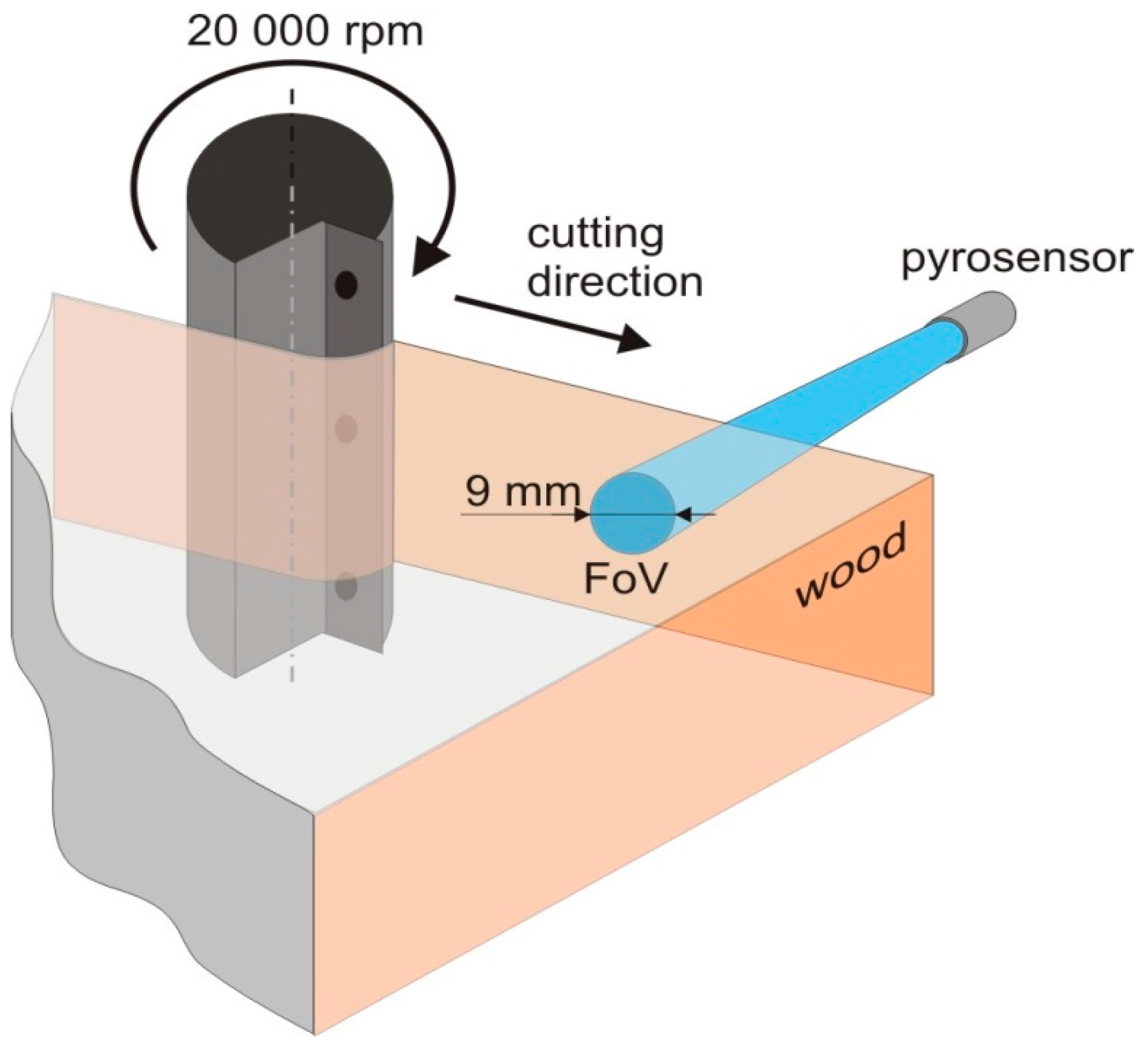
Following the experimental measurement, optimum methods for tool temperature monitoring in the process of wood milling were determined to allow the researchers to acquire accurate data associated with the changes in temperature depending upon technological parameters of milling. It emerged that measurement using the pyrometer with the temperature in the range from 15–90 °C is the optimal way to measure tool temperature. Due to 10:1 optics and the high-resolution processor for accurate measurement, the distance of 90 mm between the pyrometer and the tool surface was found to have the best result in the target spot diameter of 9 mm on the tool surface (Figure 1). The value of 30 Hz seemed to be the optimal sampling frequency in order to record the temperature in the field of view of the pyrometer depending upon the time. This setting allows researchers to record at least 5 images during moving the tool within the pyrometer field of view also when the feed rate is high. The number of images can be considered satisfactory for the purpose of correct temperature evaluation. The value of emissivity of the target surface determined experimentally is 0.9. The point on the sample where the tool temperature started to be recorded was another important parameter. In the process of removing the layer, the distance of 470 mm was determined as the distance of tool–workpiece–surrounding environment thermal equilibrium.
3. Results and Discussion
The proposed methods were verified using three basic parameters affecting the process of milling: wood species, thickness of the removed layer and feed rate. The results are shown in detail in the following tables and graphs. Temperature data are in the form of UxRy, where x is a numerical value of thickness of the removed layer (1, 3 resp. 5 mm) and y is a value of feed rate (1, 2, 3, 4 or 5 m/min). Each of the three wood species (English oak, European beech, Norway spruce) was measured individually. The results are in Table 1, Table 2, Table 3, Table 4, Table 5 and Table 6.
3.1. English Oak Machining
3.2. European Beech Machining
3.3. Norway Spruce Machining
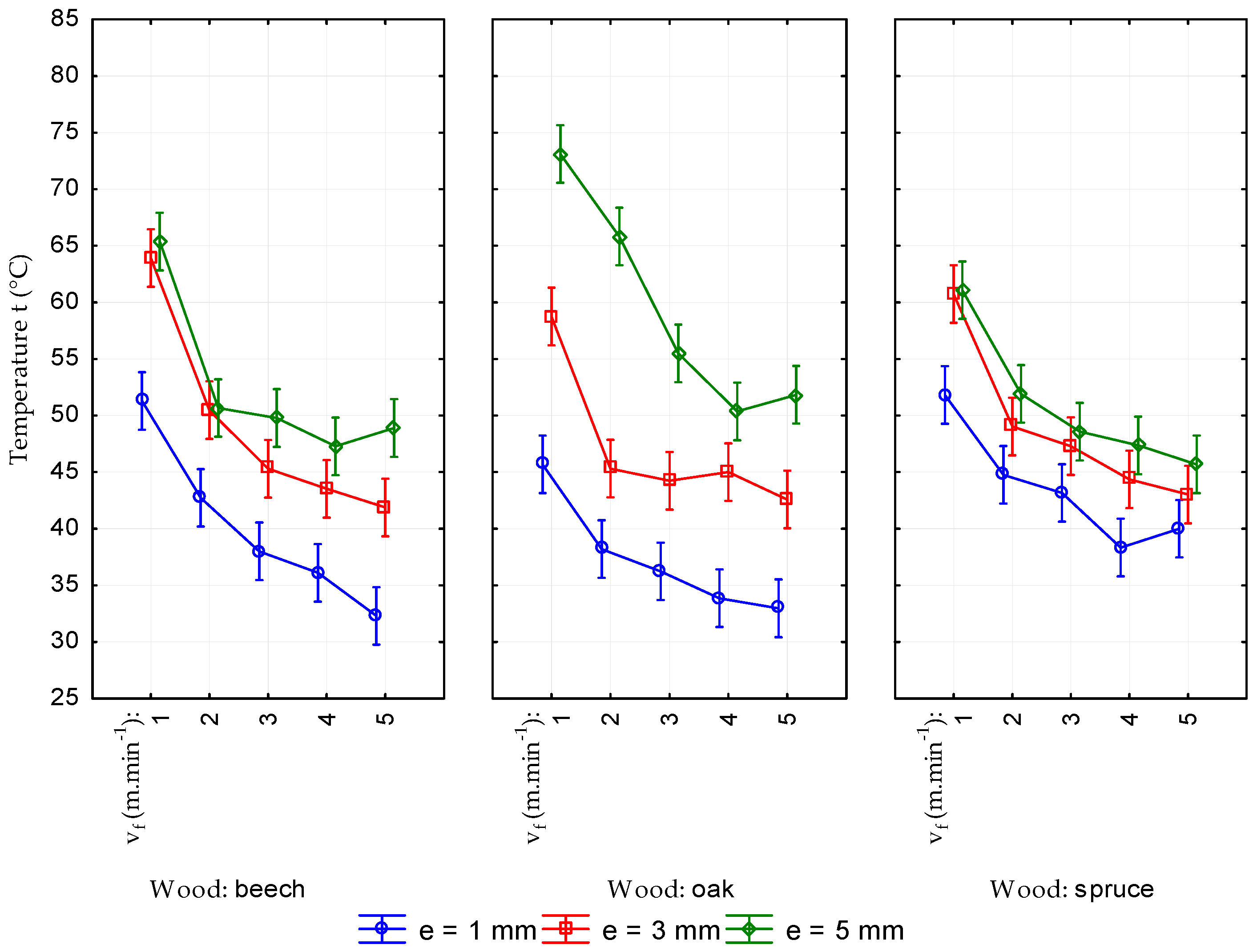
Absolute values of the tool temperature recorded in the process of machining of solid wood are shown in Figure 2. Following the graphs, it can be seen that there is an increase in the temperature when the thickness of the removed layer increases. Observing all three types of wood species, the same trend relating to the size of removed chips is noted. Nominal chip thickness increases when the thickness of removed layer increases. Friction which is a source of heat and results in higher tool temperature increases as well.
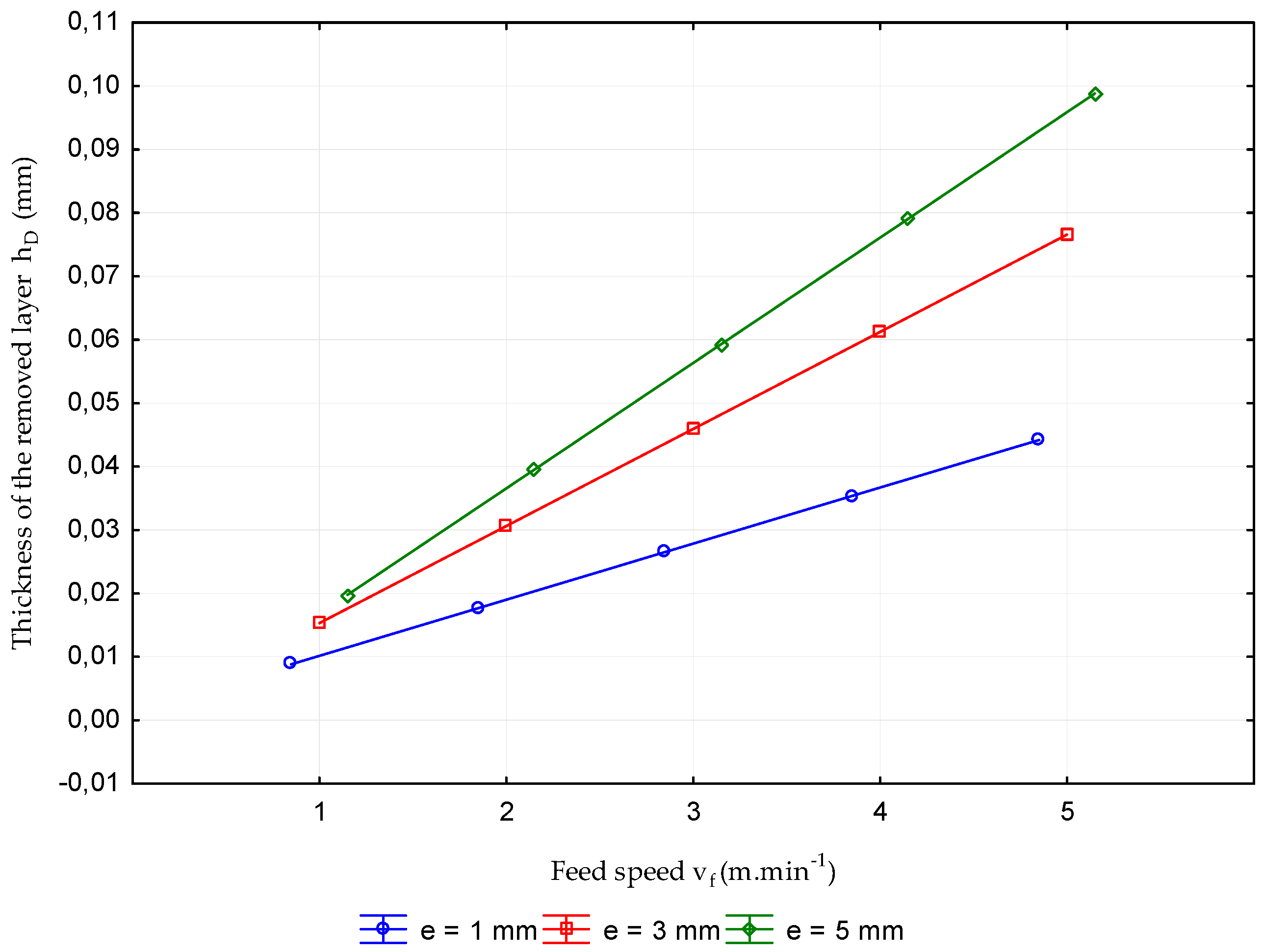
The other fact observed in the experiment is that the tool temperature decreases with the increase in the feed rate. The findings can be seen in all measurements regardless the wood species or the thickness of removed layer. This trend is caused by the thermo-physical properties of wood. The value of wood thermal diffusivity is low (α = 0.10–0.50 × 10⁶ m2·s−1 depending upon the anatomical direction and wood species). Therefore, the heat expansion resulting from friction between the tool and the surface is very slow. When the feed rate and the chip thickness is low, a thin wood layer with higher temperature due to previous cuts is cut with the tool. Higher tool as well as wood temperature is caused by further friction. When there is an increase in the feed rate, the chip thickness increases, too (Figure 3). Thus the thickness of layers cut with a tool increases, but the effect of the heat caused by previous cuts is not so significant. The fact that the tool temperature is affected, to a large extent, by direct friction can be considered the result. Therefore, the final tool temperature is lower.
An increase in the tool temperature with wood species (wood density) can be observed at higher thickness of the removed layer. The increase in tool temperature is highest when the wood density is highest (English oak) and, vice versa, smallest when the wood density is lowest (Norway spruce). This shows that there is a relation between the tool temperature and density of material in the process of machining. However, in the case of low values of thickness of the removed layer the increase in temperature was lower due to lower friction. The effect of tool temperature increase with density was suppressed with the effect of nominal chip thickness increase with density [48], which caused decrease in the tool temperature with wood species (wood density).
Acquired data were evaluated using statistical analysis of variance (Table 7). Following the analysis the fact that thickness of removed layer and feed rate are statistically significant can be stated. The parameter of wood species is only partially statistically significant. On the basis of statistical evaluation, observed parameters can be ordered according to their significance as follows: thickness of the removed layer, feed rate and wood species.
As was identified in the theoretical overview of the issue, friction in the process of removing chips is considered the source of heat. Acquired data showed (Figure 2) that an increase in feed rate results in a decrease in the tool temperature. On the other hand, an increase in nominal chip thickness is caused by an increase in feed rate (Figure 3). The results correspond with the following statement: when the nominal chip thickness increases, the pressure on the cutting wedge increases as well. It results in a decrease in friction, and thereby the tool temperature decreases. The findings that an increase in the thickness of the removed layer can cause an increase in tool temperature were proven as well. According to the theory of cutting, where it is mentioned that “an increase in the coefficient of friction is caused by an increase in the thickness of removed layer“ and “friction is a source of heat”, the effect of thickness of the removed layer corresponds with the theoretical knowledge.
Following the theoretical overview, an increase in the tool temperature with wood species (wood density) can be observed at higher thicknesses of the removed layer. It was statistically confirmed when the value of thickness of the removed layer was the highest and in case of feed rate, that the values were the three lowest ones (Table 8, Table 9 and Table 10). In the case of low values of thickness of the removed layer, the effect of nominal chip thickness increasing with density was dominant causing a statistically confirmed decrease in the tool temperature with wood species (wood density). In the case of the middle value of thickness of the removed layer, there was not a statistically confirmed difference in the change of the tool temperature with wood density.
4. Conclusions
As has been shown, the proposed methods are suitable for observing the effect of the parameters of the milling process on the tool temperature because of using the relevant parameters affecting the temperature of the cutting tool. Moreover, they allow the researchers to record the temperature in the tool–material interaction in real time.
Based on the measured results, the following conclusions can be drawn:
- Due to the process of machining, there is an increase in the tool temperature in the range from 13.9 ÷ 55.4 °C within the distance of the first 470 mm of the cut.
- A statistically significant relation between the tool temperature and feed rate and the thickness of the layer was proven. An increase in feed rate results in a decrease in tool temperature. An increase in thickness of the removed layer results in an increase in tool temperature.
- A statistically significant effect of wood species was observed. When the value of the thickness of the removed layer was the highest and the values of feed rate were the three smallest, an increase in the tool temperature with wood density was observed. In the case of low values of thickness of the removed layer, a decrease in the tool temperature with wood density was observed.
The given method can be applied in the process of so-called “adaptive machine-tool control of technological parameters of CNC machining centres” allowing the researchers to monitor the machining process in real time and to manage it actively. The research can be considered the first step in its creation. Creating the system must be supported by the experimental observation where other parameters, not only those mentioned, would be included. In particular, the parameters associated with the tool temperature, e.g., tool wear, surface defects or its burning have to be analysed. Following the acquired data, response algorithms (for setting the optimum cutting conditions or determining the right time for tool change) could be created, whereby the potential for the use of tool temperature measurement in the process of adaptive machine-tool control arises.
Author Contributions
Conceptualization, R.K.; methodology, R.I.; validation, M.N.; formal analysis, R.K.; investigation, R.I.; resources, Ľ.K.; data curation, T.G.; writing—original draft preparation, Ľ.K.; writing—review and editing, Ľ.K.;
Funding
This research was funded by VEGA 1/0485/18 “Machining strategies for specific agglomerated material separation models for nesting milling on a CNC machining centre” and APVV-14-0506 “Lowering of formaldehyde emission from wood-based panels by environmental progressive modification of polycondensation adhesives with biopolymers from leather waste, natural nanofillers, additives and activators”.
Conflicts of Interest
The authors declare no conflict of interest.
References
- Gaff, M.; Sarvašová-Kvietková, M.; Gašparík, M.; Slávik, M. Dependence of roughness change and crack formation on parameters of wood surface embossing. Wood Res. 2016, 61, 163–174. [Google Scholar]
- Očkajová, A.; Kučerka, M.; Krišťák, Ľ.; Igaz, R. Granulometric analysis of sanding dust from selected wood species. Bioresources 2018, 13, 7481–7495. [Google Scholar] [CrossRef]
- Vlčková, M.; Gejdoš, M.; Němec, M. Analysis of vibration in wood chipping process. Akustika 2017, 28, 106–110. [Google Scholar]
- Klaric, K.; Greger, K.; Klaric, M.; Andric, T.; Hitka, M.; Kropivsek, J. An Exploratory Assessment of FSC Chain of Custody Certification Benefits in Croatian Wood Industry. Drvna Ind. 2016, 67, 241–248. [Google Scholar] [CrossRef]
- Očkajová, A.; Banski, A. Granularity of sand wood dust from narrow belt sanding machine. Acta Fac. Xylologiae 2013, 55, 85–90. [Google Scholar]
- Kučerka, M.; Očkajová, A. Thermowood and granularity of abrasive wood dust. Acta Fac. Xylologiae 2018, 60, 43–52. [Google Scholar]
- Klement, I.; Vilkovská, T.; Baranski, J.; Konopka, A. The impact of drying and steaming processes on surface color changes of tension and normal beech wood. Dry. Technol. 2018. in Press. [Google Scholar] [CrossRef]
- Welzbacher, C.B.; Brischke, C.; Rapp, A.O. Influence of treatment temperature and duration on selected biological, mechanical, physical and optical properties of thermally modified timber. Wood Mater. Sci. Eng. 2008, 2, 66–76. [Google Scholar] [CrossRef]
- Gejdoš, M.; Lieskovská, M.; Slančík, M.; Němec, M.; Danielová, Z. Storage and fuel quality of coniferous wood chips. Bioresources 2015, 10, 5544–5553. [Google Scholar] [CrossRef]
- Mračková, E.; Krišťák, Ľ.; Kučerka, M.; Gaff, M.; Gajtanska, M. Creation of wood dust during wood processing: Size analysis, dust separation, and occupational health. Bioresources 2016, 11, 209–222. [Google Scholar] [CrossRef]
- Sedlecký, M.; Sarvašová Kvietková, M. Surface waviness of medium-density fibreboard (MDF) and edge-glued panel EGP after edge milling. Wood Res. 2017, 62, 459–470. [Google Scholar]
- Sedlecký, M.; Kvietková, S.M.; Kminiak, R. Medium-density Fiberboard (MDF) and Edge-glued Panels (EGP) after Edge Milling-Surface Roughness after Machining with Different Paraeters. Bioresources 2018, 13, 2005–2021. [Google Scholar] [CrossRef]
- Curti, R.; Marcon, B.; Denaud, L.; Collet, R. Effect of Grain Direction on Cutting Forces and Chip Geometry during Green Beech Wood Machining. Bioresources 2018, 13, 5491–5503. [Google Scholar]
- Stewart, H.A. High–temperature halogenation of tungsten carbide-cobalt tool material when machining MDF. For. Prod. J. 1992, 42, 27–31. [Google Scholar]
- Kvasnová, P.; Novák, D.; Novák, V. Laser welding of aluminium alloys. Manuf. Technol. 2017, 17, 892–898. [Google Scholar]
- Wei, W.H.; Xu, J.H.; Fu, Y.C.; Yang, S.B. Tool wear in turning of titanium alloy after thermohydrogen treatment. Chin. J. Mech. Eng. 2012, 25, 776–780. [Google Scholar] [CrossRef]
- Troppová, E.; Tippner, J.; Hrčka, R.; Halachan, P. Qasi-stationary measurements of lignamon thermal properties. Bioresources 2013, 8, 6288–6296. [Google Scholar] [CrossRef]
- Hrčka, R.; Babiak, M. Some non-traditional factors influencing thermal properties of wood. Wood Res. 2012, 57, 367–374. [Google Scholar]
- Hrčka, R.; Babiak, M.; Németh, R. High temperature effect on diffusion coefficient. Wood Res. 2008, 53, 37–46. [Google Scholar]
- Kubovský, I.; Oberhofnerová, E.; Kačík, F.; Pánek, M. Surface changes of selected hardwoods due to weather conditions. Forests 2018, 9, 557. [Google Scholar] [CrossRef]
- Chardin, A. Laboratory studies of temperature distribution on the face of a sawtooth. In Proceedings of the 4th Wood Machining Seminar, Berkeley, CA, USA, 4–6 December 1973; pp. 67–84. [Google Scholar]
- Konov, V.N. Research of the temperature field on the circular saw blades in the wood cutting process. Working machines, tools in machining of the wood. Univ. Textb. Sci. Works 1982, 9, 3–6. [Google Scholar]
- Okumura, S. A theoretical approach to the cutting edge temperature in interrupted cutting of wood. Mem. Coll. Agric. Kyoto Univ. 1985, 127, 29–36. [Google Scholar]
- Ishihara, M.; Noda, N.; Ootao, Y. Analysis of dynamic characteristics of rotating circular saw subjected to thermal loading and tensioning. J. Therm Stress. 2010, 33, 501–517. [Google Scholar] [CrossRef]
- Ratnasingam, J.; Pew, M.; Ramasamy, G. Tool temperature and cutting forces during the machining of particleboard and solid wood. J. Appl. Sci. 2010, 10, 2881–2886. [Google Scholar]
- Svoreň, J.; Javorek, Ľ.; Krajčovičová, M.; Klobušiaková, K.; Kubovský, I.; Kminiak, R. The effect of the circular saw blade body structure on the concentric distribution of the temperature along the radius during the wood cutting process. Wood Res. 2017, 62, 427–436. [Google Scholar]
- Aguilera, A.; Barros, J.L. Sufrace roughness assessment on medium density fibreboard rip sawing using acoustic signals. Eur. J. Wood Wood Prod. 2012, 70, 369–372. [Google Scholar] [CrossRef]
- Chen, C.C.; Liu, N.M.; Chiang, K.T.; Chen, H.L. Experimental investigation of tool vibration and surface roughness in the precision end-milling process using the singular spectrum analysis. Int. J. Adv. Manuf. Technol. 2012, 63, 797–815. [Google Scholar] [CrossRef]
- De Deus, P.R.; Alves, M.C.D.S.; Vieira, F.H.A. The quality of MDF work pieces machined in CNC milling machine in cutting speeds, feed rate, and depth of cut. Meccanica 2015, 50, 2899–2906. [Google Scholar] [CrossRef]
- Csanady, E. Heat transfer and thermal loading in wood cutting tools. In Proceedings of the 11th International Wood Machining Seminar, Oslo, Norway, 25–27 May 1993; The Norwegian Institute of Wood Technology: Oslo, Norway, 1993; pp. 486–494. [Google Scholar]
- Eyma, F. Caracterisation des Efforts de Coupe de Differentes Essences de Bois a L’aide de Leurs Paramétres Mécaniques. Ph.D. Thesis, Université Henri Poincaré Nancy 1, Nancy, France, 2002. [Google Scholar]
- Novák, V.; Rousek, M.; Kopecký, Z. Assessment of Wood Surface Quality Obtained During High Speed Milling by Use of Non-Contact Method. Drvna Ind. 2011, 62, 105–113. [Google Scholar] [CrossRef]
- Hernandez, R.E.; Passarini, L.; Koubaa, A. Effects of temperature and moisture content on selected wood mechanical properties involved in the chipping process. Wood Sci. Technol. 2014, 48, 1281–1301. [Google Scholar] [CrossRef]
- Barcík, Š.; Kvietková, M.; Bomba, J.; Siklienka, M. Dřevoobráběcí Nástroje–Údržba a Provozování; Powerprint: Praha, Czech Republic, 2013; p. 355. [Google Scholar]
- Sheikh-Ahmad, J.Y.; LEwandowski, C.M.; Bailey, J.A.; Steward, J.S. Experimental and Numerical Method for Determining Temperature Distribution in Wood Cutting Tool. Exp. Heat Transf. 2003, 16, 255–271. [Google Scholar] [CrossRef]
- Horman, I.; Busuladzic, I.; Azemovic, E. Temperature Influence on Wear Characteristics and Blunting of the Tool in Continous Wood Cutting Process. Procedia Eng. 2014, 69, 133–140. [Google Scholar] [CrossRef]
- Zhu, Z.; Guo, X.; Na, B.; Liang, X.; Ekevad, M.; Ji, F. Research on cutting performance of ceramic cutting tools in milling high density fiberboard. Wood Res. 2017, 62, 125–138. [Google Scholar]
- Sommer, F.; Dan, T.; Kern, F.; Gadow, R.; Heisel, U. Medium density fiberboard machining and wear behavior of injection-molded ceramic composite wood cutting tools. Int. J. Appl. Ceram. Technol. 2013, 12, 147–156. [Google Scholar] [CrossRef]
- Sommer, F.; Kern, F.; Gadow, R. Injection molding of ceramic cutting tools for wood-based materials. J. Eur. Ceram. Soc. 2013, 33, 3115–3122. [Google Scholar] [CrossRef]
- Stewart, H.A. Cryogenic treatment of tingsten carbide reduces tool wear when machining medium density fiberboard. For. Prod. J. 2004, 54, 53–56. [Google Scholar]
- Reid, A.S.; Stewart, H.A.; Rapp, R.A. High-temperature reactions of tungsten carbide-cobald tool material with MDF. For. Prod. J. 1991, 41, 12–18. [Google Scholar]
- Guo, X.; Zhu, N.; Wang, J.; Yuan, G.; Zhu, Z.; Na, B.; Cao, P. Effect of cutting speed and chip thickness on cutting forces and surface roughness of fiberboard. J. For. Eng. 2016, 1, 114–117. [Google Scholar]
- Gisip, J.; Gazo, R.; Stewart, H.A. Effects of refrigerated air on tool wear. Wood Fiber Sci. 2007, 39, 443–449. [Google Scholar]
- Gisip, J.; Gazo, R.; Stewart, H.A. Effects of cryogenic treatment and refrigerated air on tool wear when machining medium density fiberboard. J. Mater. Process. Technol. 2009, 209, 5117–5122. [Google Scholar] [CrossRef]
- Gazo, R.; Gisip, J.; Stewart, H.A. Reducing Tool Wear by Cryogenic Treatment and Cooling with Refrigerated Air when Processing Medium Density Fiberboard. In Wood Machining; ISTE Ltd. and John Wiley & Sons, Inc.: London, UK, 2011; pp. 83–113. [Google Scholar]
- Wei, W.; Li, Y.; Xue, T.; Tao, S.; Mei, C.; Zhou, W.; Wang, J.; Wang, T. The Research Progress of Machining Mechanisms in Milling Wood-Based Materials. Bioresources 2018, 13, 2139–2149. [Google Scholar] [CrossRef]
- Pfeiffer, R.; Collet, R.; Denaud, L.; Fromentin, G. Analysis of chip formation mechanisms and modeling of slabber process. Wood Sci. Technol. 2014, 49, 1–18. [Google Scholar]
- Burdon, R.D.; Kibblewhite, R.P.; Riddell, M.J.C. Wood density and kraft fibre and pulp properties of four pinus radiate provenances. N. Z. J. For. Sci. 1999, 29, 214–224. [Google Scholar]
Figure 1.
Model of the experiment to measure the tool temperature in the process of machining.

Figure 2.
Average values of tool temperature in the process of wood machining when the values of thickness of the removed layer and feed rate vary.
Figure 2.
Average values of tool temperature in the process of wood machining when the values of thickness of the removed layer and feed rate vary.

Figure 3.
Nominal chip thicknesses depending upon thickness of the removed layer and feed rate.


Table 1.
Average values of tool temperature, variances, and surface temperature prior to machining of English oak.
Table 1.
Average values of tool temperature, variances, and surface temperature prior to machining of English oak.
| Thickness of Removed Layer of 1 mm | |||||
| U1R1 | U1R2 | U1R3 | U1R4 | U1R5 | |
| ttool | 45.66 | 38.20 | 36.24 | 33.85 | 32.96 |
| stdev | 2.99 | 2.60 | 2.28 | 1.77 | 1.48 |
| tambient | 17.34 | 17.42 | 16.62 | 17.31 | 17.60 |
| Thickness of Removed Layer of 3 mm | |||||
| U3R1 | U3R2 | U3R3 | U3R4 | U3R5 | |
| ttool | 58.75 | 52.32 | 44.23 | 45.00 | 42.58 |
| stdev | 5.96 | 3.75 | 3.22 | 4.60 | 3.36 |
| tambient | 18.15 | 18.01 | 17.13 | 17.98 | 17.43 |
| Thickness of Removed Layer of 5 mm | |||||
| U5R1 | U5R2 | U5R3 | U5R4 | U5R5 | |
| ttool | 73.12 | 63.82 | 55.50 | 50.37 | 51.83 |
| stdev | 5.70 | 4.14 | 2.69 | 2.60 | 3.87 |
| tambient | 17.73 | 18.21 | 18.19 | 18.11 | 18.10 |
Table 2.
Values of increased tool temperature against the temperature of the environment depending upon the thickness of the removed layer and feed rate.
Table 2.
Values of increased tool temperature against the temperature of the environment depending upon the thickness of the removed layer and feed rate.
| Thickness of Removed Layer (mm) | Feed Rate (m/min) | ||||
|---|---|---|---|---|---|
| 1 | 2 | 3 | 4 | 5 | |
| 1 | 28.3 | 20. 8 | 19.6 | 16.5 | 15.4 |
| 3 | 40.6 | 34.3 | 27.1 | 27.0 | 25.2 |
| 5 | 55.4 | 45.6 | 37.3 | 32.3 | 33.7 |
Table 3.
Average values of tool temperature, variances, and surface temperature prior to machining of European beech.
Table 3.
Average values of tool temperature, variances, and surface temperature prior to machining of European beech.
| Thickness of Removed Layer of 1 mm | |||||
| U1R1 | U1R2 | U1R3 | U1R4 | U1R5 | |
| ttool | 51.28 | 42.73 | 38.00 | 36.10 | 32.30 |
| stdev | 2.35 | 2.30 | 2.86 | 2.07 | 1.09 |
| tambient | 18.63 | 18.72 | 18.49 | 18.42 | 18.37 |
| Thickness of Removed Layer of 3 mm | |||||
| U3R1 | U3R2 | U3R3 | U3R4 | U3R5 | |
| ttool | 63.92 | 50.48 | 45.30 | 43.53 | 41.88 |
| stdev | 4.92 | 3.09 | 3.60 | 2.30 | 3.85 |
| tambient | 18.94 | 18.49 | 16.78 | 16.12 | 16.42 |
| Thickness of Removed Layer of 5 mm | |||||
| U5R1 | U5R2 | U5R3 | U5R4 | U5R5 | |
| ttool | 65.38 | 54.66 | 49.78 | 47.28 | 48.90 |
| stdev | 4.31 | 2.58 | 3.02 | 3.02 | 3.55 |
| tambient | 16.60 | 16.95 | 16.99 | 16.44 | 17.09 |
Table 4.
Values of increased tool temperature against the temperature of the environment depending upon the thickness of the removed layer and feed rate.
Table 4.
Values of increased tool temperature against the temperature of the environment depending upon the thickness of the removed layer and feed rate.
| Thickness of Removed Layer (mm) | Feed Rate (m/min) | ||||
|---|---|---|---|---|---|
| 1 | 2 | 3 | 4 | 5 | |
| 1 | 32.7 | 24.0 | 19.5 | 17.7 | 13.9 |
| 3 | 45.0 | 32.0 | 28.5 | 27.3 | 25.5 |
| 5 | 48.8 | 37.7 | 32.8 | 30.8 | 31.8 |
Table 5.
Average values of tool temperature, variances, and surface temperature prior to machining of Norway spruce.
Table 5.
Average values of tool temperature, variances, and surface temperature prior to machining of Norway spruce.
| Thickness of Removed Layer of 1 mm | |||||
| U1R1 | U1R2 | U1R3 | U1R4 | U1R5 | |
| ttool | 51.82 | 44.77 | 43.17 | 38.33 | 40.00 |
| stdev | 4.99 | 2.94 | 3.02 | 2.42 | 3.23 |
| tambient | 18.34 | 18.03 | 17.89 | 17.80 | 17.97 |
| Thickness of Removed Layer of 3 mm | |||||
| U3R1 | U3R2 | U3R3 | U3R4 | U3R5 | |
| ttool | 58.73 | 49.03 | 47.30 | 44.37 | 43.02 |
| stdev | 2.09 | 3.80 | 2.24 | 1.61 | 1.98 |
| tambient | 18.95 | 18.61 | 18.46 | 18.50 | 18.44 |
| Thickness of Removed Layer of 5 mm | |||||
| U5R1 | U5R2 | U5R3 | U5R4 | U5R5 | |
| ttool | 61.08 | 51.92 | 48.58 | 47.37 | 45.68 |
| stdev | 3.84 | 1.79 | 3.06 | 2.27 | 2.47 |
| tambient | 19.10 | 18.90 | 18.85 | 18.82 | 18.77 |
Table 6.
Values of increased tool temperature against the temperature of the environment depending upon the thickness of the removed layer and feed rate.
Table 6.
Values of increased tool temperature against the temperature of the environment depending upon the thickness of the removed layer and feed rate.
| Thickness of Removed Layer (mm) | Feed Rate (m/min) | ||||
|---|---|---|---|---|---|
| 1 | 2 | 3 | 4 | 5 | |
| 1 | 33.5 | 26.7 | 25.3 | 20.5 | 22.0 |
| 3 | 39.8 | 30.4 | 28.8 | 25.9 | 24.6 |
| 5 | 42.0 | 33.0 | 29.7 | 28.5 | 26.9 |
Table 7.
Results of the statistical analysis of variance―values of tool temperature depending upon the evaluated parameters (wood species, thickness of the removed layer, feed rate).
Table 7.
Results of the statistical analysis of variance―values of tool temperature depending upon the evaluated parameters (wood species, thickness of the removed layer, feed rate).
| SS | Degr. of Free. | MS | F | p | |
|---|---|---|---|---|---|
| Intercept | 612,993.4 | 1 | 612,993.4 | 61,377.91 | 0.000000 |
| Wood | 31.9 | 2 | 16.0 | 1.60 | 0.204708 |
| Removal e (mm) | 8709.4 | 2 | 4354.7 | 436.03 | 0.000000 |
| Feed speed vf (m·min−1) | 10,274.4 | 4 | 2568.6 | 257.19 | 0.000000 |
| Wood × Removal e (mm) | 1824.2 | 4 | 456.0 | 45.66 | 0.000000 |
| Wood × Feed speed vf (m·min−1) | 128.2 | 8 | 16.0 | 1.60 | 0.124633 |
| Removal e (mm) × Feed speed vf (m·min−1) | 244.4 | 8 | 30.6 | 3.06 | 0.002736 |
| Wood × Removal e (mm) × Feed speed vf (m·min−1) | 539.9 | 16 | 33.7 | 3.38 | 0.000024 |
| Error | 2247.1 | 225 | 10.0 |
Table 8.
Results of the statistical analysis of variance―values of tool temperature depending upon the evaluated parameters (wood species, vf = 1 m·min−1, e = 5 mm).
Table 8.
Results of the statistical analysis of variance―values of tool temperature depending upon the evaluated parameters (wood species, vf = 1 m·min−1, e = 5 mm).
| vf = 1 m·min−1 e = 5 mm | SS | Degr. of Free. | MS | F | p |
|---|---|---|---|---|---|
| Intercept | 79,667,01 | 1 | 79,667.01 | 4039.841 | 0.000000 |
| Wood | 446.19 | 2 | 223.10 | 11.313 | 0.001010 |
| Error | 295.81 | 15 | 19.75 |
Table 9.
Results of the statistical analysis of variance―values of tool temperature depending upon the evaluated parameters (wood species, vf = 2 m·min−1, e = 5 mm).
Table 9.
Results of the statistical analysis of variance―values of tool temperature depending upon the evaluated parameters (wood species, vf = 2 m·min−1, e = 5 mm).
| vf = 2 m·min−1 e = 5 mm | SS | Degr. of Free. | MS | F | p |
|---|---|---|---|---|---|
| Intercept | 56,717.12 | 1 | 56,717.12 | 6633.581 | 0.000000 |
| Wood | 848.59 | 2 | 424.30 | 49.625 | 0.000000 |
| Error | 128.25 | 15 | 8.55 |
Table 10.
Results of the statistical analysis of variance―values of tool temperature depending upon the evaluated parameters (wood species, vf = 3 m·min−1, e = 5 mm).
Table 10.
Results of the statistical analysis of variance―values of tool temperature depending upon the evaluated parameters (wood species, vf = 3 m·min−1, e = 5 mm).
| vf = 3 m·min−1 e = 5 mm | SS | Degr. of Free. | MS | F | p |
|---|---|---|---|---|---|
| Intercept | 47,349.90 | 1 | 47,349.90 | 5532.536 | 0.000000 |
| Wood | 163.92 | 2 | 81.96 | 9.577 | 0.002089 |
| Error | 128.38 | 15 | 8.56 |
© 2018 by the authors. Licensee MDPI, Basel, Switzerland. This article is an open access article distributed under the terms and conditions of the Creative Commons Attribution (CC BY) license (http://creativecommons.org/licenses/by/4.0/).
Share and Cite
MDPI and ACS Style
Igaz, R.; Kminiak, R.; Krišťák, Ľ.; Němec, M.; Gergeľ, T. Methodology of Temperature Monitoring in the Process of CNC Machining of Solid Wood. Sustainability 2019, 11, 95. https://doi.org/10.3390/su11010095
AMA Style
Igaz R, Kminiak R, Krišťák Ľ, Němec M, Gergeľ T. Methodology of Temperature Monitoring in the Process of CNC Machining of Solid Wood. Sustainability. 2019; 11(1):95. https://doi.org/10.3390/su11010095
Chicago/Turabian StyleIgaz, Rastislav, Richard Kminiak, Ľuboš Krišťák, Miroslav Němec, and Tomáš Gergeľ. 2019. "Methodology of Temperature Monitoring in the Process of CNC Machining of Solid Wood" Sustainability 11, no. 1: 95. https://doi.org/10.3390/su11010095
Note that from the first issue of 2016, this journal uses article numbers instead of page numbers. See further details here.