Design Methodology for Street-Oriented Block Housing Considering Daylight and Natural Ventilation


Department of Architecture, Dankook University, Yongin 16890, Korea
*
Author to whom correspondence should be addressed.
Sustainability 2018, 10(9), 3154; https://doi.org/10.3390/su10093154
Submission received: 31 July 2018
/
Revised: 30 August 2018
/
Accepted: 31 August 2018
/
Published: 4 September 2018
(This article belongs to the Special Issue Achieving Sustainable Village Development though Traditional and Innovative Approaches)
Abstract
:This study presents a design methodology for street-oriented block housing, as a model for gradual small-scale block-unit development, that can secure two hours of continuous access to daylight on the winter solstice at azimuth angles of 0° and 60° in Seoul, South Korea, and, in addition, developed a methodology for wind path planning for existing types of developed housing. The results of this study have confirmed the feasibility of a housing design that can secure two hours of continuous access to daylight along with no less than 200 percent of development density, achieved through the elimination of self-shadows by using distances between residential buildings and shadow characteristics according to azimuth angles. In addition, the study identified an air flow stagnation section by assessing the air flow of the exterior space of street-oriented block housing in consideration of day-lit environments, and examined a planning model that can enhance natural ventilation potential by activating the air flow of the exterior space. Wind path planning was conducted for 24 alternatives that were produced based on the developed design methodology, and the wind velocity ratio of street-oriented block housing ranged from 0.34 to 0.59. In terms of disadvantages of street-oriented block housing in securing wind paths, this study confirmed that air flow could be strengthened by adjusting the form of the lower-part opening, which is open in the direction of incoming wind, designing a staggered mass layout in high-rise masses, and combining building floor heights. The above findings of this study suggest that a performance-based approach is necessary for the improvement of environmental performance in street-oriented block housing, in consideration of azimuth angles and the prevailing wind direction from the initial phase of planning.
1. Introduction
Identifying the appropriate housing type corresponding to the street structure of a city has been a critical task in designing residential buildings in South Korea since the 2000s. The search and contemplation of new types of collective housing have been driven by the awareness and reflection on problems arising from the uniformity of tower-type residential buildings created by conventional high-density and high-rise development, disconnect in the urban context due to the closed and insulated nature of the block unit structure, and disparity in the urban scenery, and the subsequent findings have been applied to the study and designs of perimeter block housing [1]. Block unit housing is a building type that forms the premise of urban plot unit rearrangement projects based on the construction of double walls, which was legalized in 2012 as a form of small-scale gradual development; sustainable urban regeneration including block-unit housing rearrangement projects, or gradual housing area rearrangement projects [2].
In particular, block-unit housing rearrangement projects operate based on the architectural model of mid-rise, high-density, street-oriented block housing with the floor area ratio of at least 200 percent, with the aim to redevelop conventional multi-household and multi-family density regions by each block unit, but the high building-to-land ratio and wall-to-building ratio may comprise unfavorable conditions in terms of daylight and ventilation, leading to the deterioration of the residential environment. Since the layout of street-oriented housing is designed in active correspondence with the surrounding streets, it may result in unfavorable orientations for certain residential units and create an imbalance of daylight between households due to self-shadows. In addition, an air-flow stagnation area may occur in the external space depending on the form of the unit mass, causing unfavorable natural ventilation. Accordingly, in order for perimeter block housing to be used as an alternative urban housing type, there needs to be a study on a design methodology that considers the day-lit environment and natural ventilation performance while securing density at a proper scale.
Previous studies on street-oriented housing include studies on the models and legal systems of small-scale block unit rearrangement projects, which mainly focus on simulations for development density and construction types according to mitigating conditions stipulated in the Building Act and the Housing Act [3,4]. In contrast, previous studies on day-lit environments of block unit collective housing include studies on day-lit environments of courtyard-type collective [5,6,7,8,9,10,11]. The study by Kang, 2004 [5] suggested a −30° azimuth angle as the optimum azimuth angle in an analysis to identify a favorable layout angle in day-lit aspects, and the study by Hwang, 2011 [6] examined a marginal analysis of applying the current standard for distance between buildings to the context of block-type collective housing. The study by Kim, 2014 [8,9,10] presented the methodology for mass formation using shadow characteristics in courtyard-type and street-oriented housing.
Meanwhile, there have been insufficient studies on the methodology for wind path planning in street-oriented housing, and the majority of previous studies focused on wind path planning to mitigate the formation of urban heat islands in flat-type or tower-type residential apartment complexes [11,12,13,14]. In particular, most of the studies placed an emphasis on comparing differences arising from types and layouts of residential buildings [11,13], or on strengthening air flow in lower parts of buildings where the air flow is prone to stagnation [14,15].
To implement eco-friendly planning in a mild climate region such as Seoul, which faces distinct seasonal changes and a broad annual temperature range, securing the right to daylight in the winter season is a precondition for reducing heating load, and the focal point is to increase thermal comfort in exterior spaces by planning wind paths with the aim to maximize natural ventilation. Accordingly, this study analyzed characteristics of day-lit environments in perimeter block housing of street systems with azimuth angles of 0 to 60°, which is the most common form of grid-type residential areas in Seoul, and by using shadow characteristics, investigated the form of residential buildings and the methodology for layout planning with the objective to meet the standard of two consecutive daylight hours on the winter solstice, which is a performance restriction prescribed in the Enforcement Decree of the Building Act. In addition, the study identified an air flow stagnation section by assessing the air flow of the exterior space of street-oriented block housing in consideration of day-lit environments, and examined a planning model that can enhance natural ventilation potential by activating the air flow of the exterior space.
The first phase of this study examined the existing preconditions of mass formation by applying legal standards for block-unit housing rearrangement projects to prominent urban organizations in grid-type residential areas of Seoul. In the second phase, a basic simulation was conducted for Seoul with the aim to examine a design methodology and validate its effectiveness with active consideration for daylighting and wind path from the initial stage of the design with regard to the form composition of street-oriented block housing. In the third phase, a design methodology for residential buildings was presented with the aim to optimize the day-lit environment of households within the blocks at azimuth angles of 0° and 60° based on properties and principles of shadows, without hindering two hours of continuous access to daylight on the exterior peripheral face of adjacent blocks. The fourth phase examined additional ways to adjust detailed masses so as to improve ventilation performance through a connection between the wind paths and exterior spaces of street-oriented block housing. For the assessment of environmental performance, in order to verify and validate the applied principles, a simulation was performed by using Autodesk Ecotect for daylight hours and Flow Design for wind blow patterns and wind velocity.
2. Materials and Methods
The rational architectural shift in urban spaces towards street-oriented block housing is likely to occur in grid-type residential areas with infrastructure in a relatively favorable state. In the second chapter, grid-type residential areas of Seoul were topologically examined to identify the most common azimuth angles, the scale of the urban block, and street systems. Based on these street systems, we examined the basic principles for daylight optimization and wind path planning and verified a design methodology that can be applied and utilized for street-oriented block housing through a three-dimensional simulation. The calculations of daylighting hours were based on legal standards stipulated as two consecutive hours of continuous access to daylight or four or more hours of accumulated daylight on the winter solstice in Seoul. In addition, a simulation for wind velocity and wind field was carried out to compare wind velocity ratios on the basis of the annual mean wind velocity and the prevailing wind direction in Seoul throughout the year.
2.1. Street Systems in Prominent Grid-Type Residential Areas of Seoul and Basic Preconditions
Daylight in residential buildings of perimeter block housing is complexly affected by the relationships between the height of buildings and the width of roads, the size of exterior spaces, distances between adjacent residential buildings, and azimuth angles [5,8]. Therefore, there is a need to first establish roads and block systems through a representative layout analysis of grid-type residential areas. The most favorable precondition for street-oriented block housing is a grid-type residential area due to the relatively favorable state of its infrastructure among 2nd class residential districts, while the environmental aspect emphasizes the importance of azimuth angle, block width, and road width. With reference to previous studies by Im, 2012 [16] and other researchers [17,18], eight prominent areas with a high plot density were selected in order to set up sample block structure in terms of azimuth angle, block width, and road with. The examined areas of 2nd class residential districts are Bomundong, Yeokcheondong, Hwagokdong, Meonmokdong, Junggokdong, Banbaedong, Shinsadong, and Ilwondong in urban development sequence.
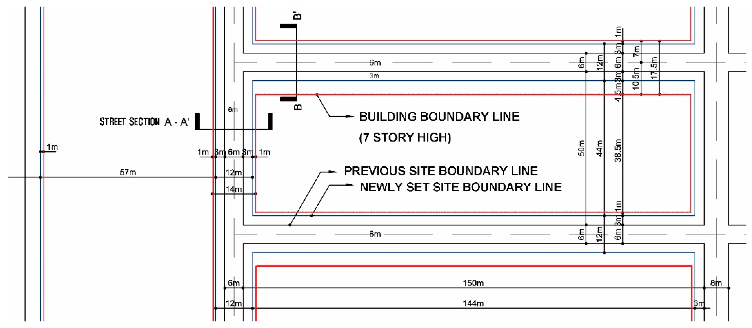
In terms of the street system, main arterial roads or 25 m-wide main roads abruptly connect to small roads of around 6–8 m in width for pedestrian and vehicle mixed use, or to driveways not exceeding 4 m in width. Plots are subdivided in a multi-column structure, and blocks vary in size with the short side measuring at about 50–60 m and the long side 120–180 m. The standard used assumes that the block is oriented due north at an azimuth angle of 0°, while rotation in the clockwise direction corresponds to a plus azimuth angle, and rotation in the counterclockwise direction a minus azimuth angle. The day-lit environment at an azimuth angle ranging from +15° to −15° is similar to that at an azimuth angle of 0°. Considering all of the above, Sample Block Structure 1 shown in Figure 1 was set at an azimuth angle of 0° with the short side measuring 50 m, the long side 150 m, and the road 6 m in width, whereas Sample Block Structure 2 was set at an azimuth angle of 60° with the short side measuring 60 m, the long side 150 m.
Sample Block Sample Block Structure 1 in Figure 2 presents diagrams for the architectural slant line restriction for daylight in the due north direction, the architectural slant line restriction for daylight in the lighting direction, and the diagonal plane control by street width, which apply to Seoul Metropolitan City’s block-unit housing rearrangement projects. Assuming a seven-story mass, the minimum distance from the site boundary line was 7.5 m on the northward side and at least 3.3 m on the other three sides.
For the purpose of the simultaneous maintenance and rearrangement of urban environments, assuming a small-scale block-unit development, roads should be widened in order to separate pedestrian and vehicle traffic. Accordingly, in this study, the existing driveways within the block were integrated with the exterior spaces for widened sidewalks, and in the process, the site boundary line was adjusted to move 3 m inwards. The architectural slant line restriction for daylight remained the same as before, since the standard line was derived from the central line of roads. Figure 1 presents the typology of street-oriented block housing based on the distance between the building and the newly set site boundary line measuring at 4.5 m on the northward side, and 1 m on the other three sides.
2.2. Understanding and Use of Shadow Characteristics
2.2.1. Daylight Standards in Collective Housing and Calculation of Daylight Hours
The standard for securing daylight in collective housing is prescribed in Article 53 of the Building Act and Article 86 of the Enforcement Decree of the Building Act, which define the limits on heights for securing daylight, etc. The Enforcement Decree stipulates the guarantee of the right to daylight by two standards: Securing explicit distances to guarantee the right to daylight between buildings facing each other; or meeting two or more consecutive hours of continuous access to daylight for every household within the site concerned between 9:00 a.m. and 3:00 p.m. on the winter solstice (Standard 1). In addition, legal precedents on the right to daylight acknowledge the need to secure four or more hours of accumulated daylight between 8:00 a.m. and 4:00 p.m. on the winter solstice (Standard 2).
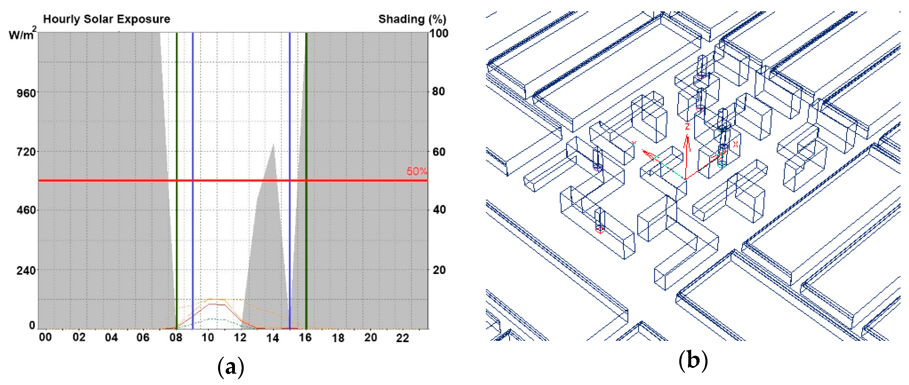
Although the Building Act stipulates specific performance restrictions on the right to daylight, in reality, collective housing is designed based on the minimum distance between residential buildings that meets the minimum legal obligation, regardless of the orientation and formation of the residential buildings. Such a design method faces limits in terms of securing daylight for every household and shows inadequacies if the distance standard stipulated by the Building Act is applied to perimeter block housing, which is closely affected by the street system [6,8,9,10]. Accordingly, a study on the methodology for a form designed to secure two consecutive hours of continuous access to daylight for every household may open possibilities toward solving the problem of day-lit environment in street-oriented block housing. Generating daylight simulations using the Autodesk Ecotect program, this study calculated the duration for which daylight is received in no less than 50 percent of the total area of the living room balcony window (4 m in width, 2.3 m in length), which meets the legal standard, as daylight hours in Standard 1 (Blue line in Figure 3a) and Standard 2 (Green line in Figure 3a).
Since day-lit environments are influenced by adjacent blocks, a simulation was performed by modelling a surrounding environment consisting of a five-story single mass as shown in Figure 3b (1.5 m away from the site boundary line, with the application of the architectural slant line restriction for daylight in the due north direction and the diagonal plane control by street width in a 6 m-wide road system). The household unit is oriented south-east at an azimuth angle of 0°, southeast-southwest at an azimuth angle of 60°.
2.2.2. Basic Simulation for Identifying Shadow Characteristics
(1) Identification of the Distance between Parallel Buildings at Each Azimuth Angle
Calculating the optimal number of floors satisfying the criteria for daylight hours or predicting whether the exterior peripheral face facing the road satisfies such criteria is possible through the use of the distance between buildings that satisfies the legal standards for daylight hours at each azimuth angle applicable to a specific area. In this study, the azimuth angle was set to zero when the block is oriented due south and the azimuth angle was rotated in the clockwise direction ranging from 0° to 90° and in the counterclockwise direction from 0° to −90° at intervals of 15°, in an attempt to identify changes in the day-lit environment. A simulation was conducted using a seven-story residential building measuring 100 m in block length, 11 m in individual unit depth, and 20 m in height. The changes in the daylight hours on the first floor of the residential buildings located behind the subject were checked to calculate the minimum distance between buildings that can secure the right to light on the first floor.
As indicated in Table 1, the results showed that the minimum distance between buildings was 1.8 h when the azimuth angle was due south, and the distance between buildings that satisfies the standard of two continuous hours of daylight sharply declined to 0.7 h when the angle was in the direction of due east or due west. Meanwhile, the difference at each azimuth angle was insignificant with regard to the minimum distance between residential buildings in accordance with the standard of four hours of accumulated daylight, and securing the four hours of accumulated daylight is impossible when the azimuth angle approaches due west or due east.
To verify these results, a simulation was performed using the basic model for a courtyard-type building, which refers to a seven-story residential building measuring 100 m in block length, 65 m in breadth, 11 m in individual unit depth, and 20 m in height. Based on the standard of minimum distance between buildings at an azimuth angle of 0° [0°/−90° (the azimuth angle of the long side/short side)] and at an azimuth angle of 60° [60°/−30°], the width of the road was determined to conduct a simulation. The simulation results showed that every household met the standard of two consecutive daylight hours in the day-lit environment of the exterior peripheral face when the distance between the south-north adjacent buildings was 36 m (1.8 h) and the distance between the east-west adjacent buildings was 15 m (0.75 h) at the azimuth angle of 0°, while they were 14 m (0.7 h) and 25 m (1.25 h), respectively, at the azimuth angle of 60°/−30°.
(2) Identification and Resolution of Areas Affected by Daylight Interference
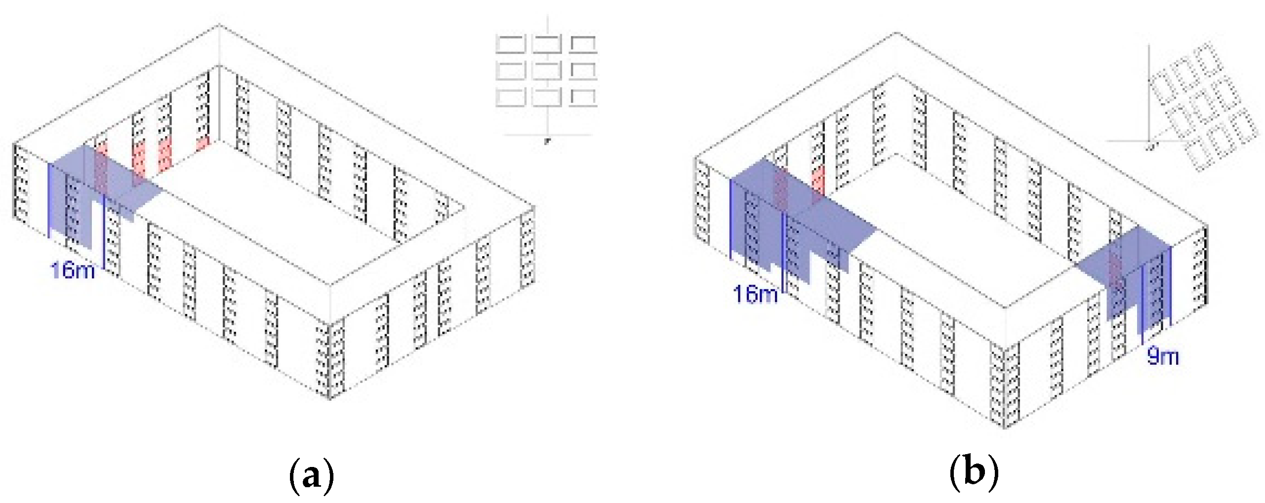
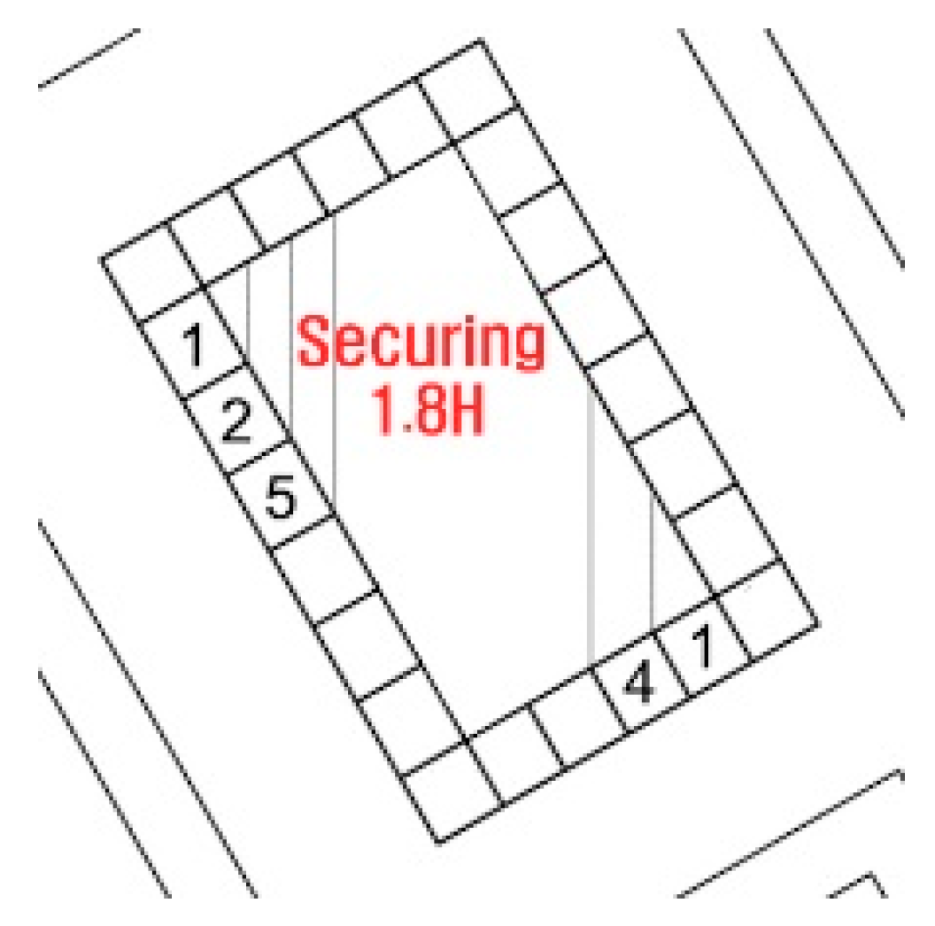
Even if the distance between parallel buildings at each azimuth angle was met, the daylight hours may not be satisfied due to self-shadows arising from masses located in the south, considering the characteristics of the shape of residential buildings. Red areas in Figure 4 presents the results of identifying the locations of self-shadows that occur in the internal peripheral face at the azimuth angle of 0°, 60° in a courtyard-type residential building measuring 100 m in length and 65 m in breadth. Thus, it is necessary to introduce light in order to resolve the problem of self-shadows by opening parts of the buildings. As indicated in blue areas in Figure 4, for instance, it may be possible to open a part of South building at the azimuth angle of 0°, Southwest building and Southeast building corners at the azimuth angle of 60°. The exact scope covered by opening the corner areas varied depending on the azimuth angle and the height of the building. However, one of the most effective methods to remove the source of self-shadows was to construct the corners in the form of steps or with an opening of a certain length (at azimuth angle 0°—16 m at the south wing; at azimuth angle 60°—16 m in the southwest corner, 9 m in the southeast corner) so as to secure a distance of 1.8 H in the corner areas pointing due north as shown in Figure 5.
2.3. Basic Directions of Wind Path Planning
2.3.1. Application of Basic Principles and Preconditions of Simulations
Maintaining proper wind velocity and wind pressure through air flows within collective housing blocks facilitate the emission of heat and pollutants, enhancing thermal comfort in exterior spaces and allowing smooth natural ventilation and wind flow within the residential unit. In general, the factors influencing wind field and airflow patterns are distance between buildings, layouts and form composition of residential buildings, height of buildings, pilotis, and openings. Airflow patterns, unlike daylight hours, are difficult to quantify as they are based on hydrodynamics and highly sensitive to changes in their surroundings. However, the main points of previous studies in terms of a systematic methodology to facilitate air flows show that wind velocity increases in proportion to the degree of openness of pilotis in the lower parts of apartment complexes, and that the building coverage ratio and blockage ratio are also relative to the wind velocity ratio [11,12]. Meanwhile, it was found that voids installed in mid-rise buildings (20 m) have no significant effect in the improvement of ventilation and wind flow of exterior spaces [13,14,15]. Moreover, airflows also intensified following an increase in wind pressures arising from differences in building heights. Since street-oriented collective houses are arranged in an L shape or a Linear shape along a street, they generally show reduced ventilation performance, or higher building coverage ratio and blockage ratio and stagnant air flows in the lower parts of the buildings due to wind shadow, compared to tower-type apartment buildings [11,12,13,14,15]. Therefore, through the basic simulation, we attempted to create openings in lower parts of the buildings so as to maximize wind inlet in the prevailing wind direction and assess the effects created by continuous exterior spaces, and examine the effectiveness of mitigating stagnant airflows by increasing the mass height without affecting daylight hours.
In this study, the wind velocity was set at 2.4 m/s, which is the annual average in Seoul over 10 years, the wind direction as the northeast as the prevailing wind direction on an annual basis. The wind tunnel size was five times the height of the building from the windward, and 10 times from the leeward, in order to properly reflect the wind vortices in the area in which the slipstream created by the building recirculates, and the simulation was performed over four hours. The input condition of the wind velocity applied the log-law and ground illumination category A (Urban), determining the incoming wind velocity as the vertical profile of the wind velocity. For each type, a 5 m × 5 m grid was set at a height of 1.5 m from the ground as the measuring point to calculate the mean wind velocity. The wind velocity ratio is defined as wind velocity within the building complexes divided by the velocity of the wind blowing toward the complex. In order to identify aspects such as the minimum distances between parallel masses and an efficient opening size in street-oriented housing, this study conducted a basic test using the method outlined below.
2.3.2. Basic Simulation for Effective Wind Path Planning
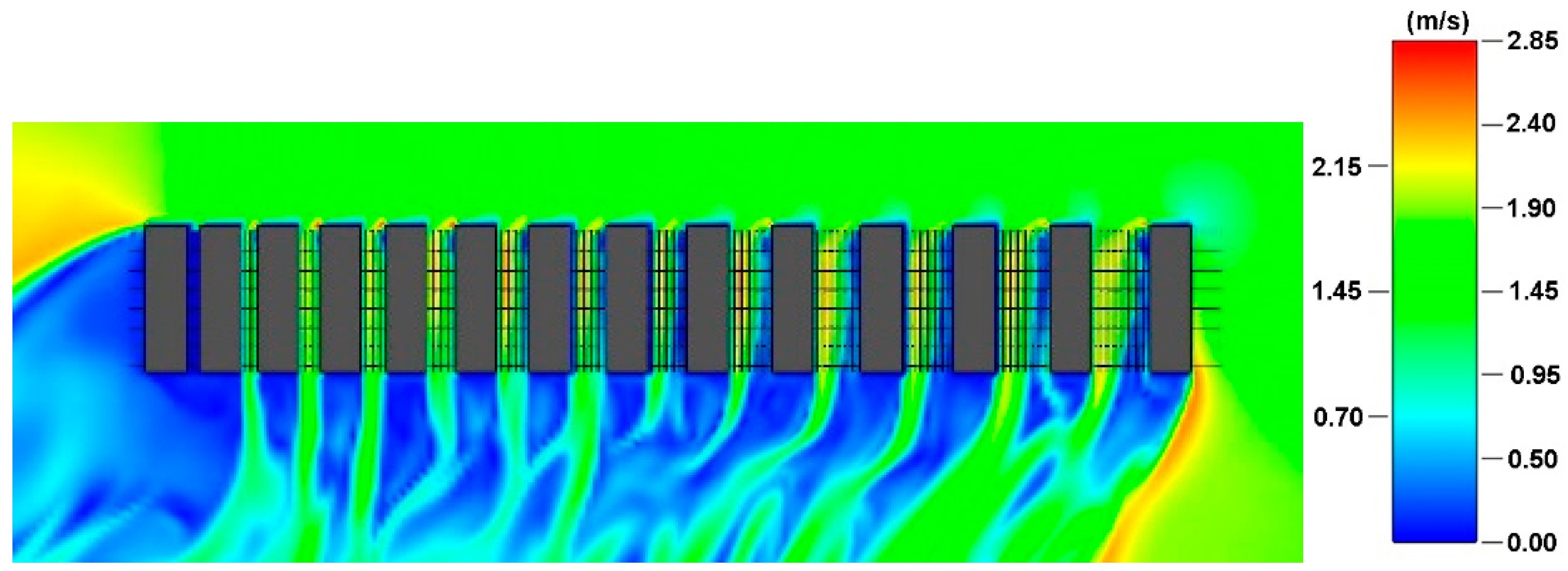
(1) Relationship between the Distance between Buildings and the Wind Velocity
To calculate the distance between two buildings with the potential for the inflow of northeasterly wind, the mean wind velocity was measured by changing the distance between seven-story masses, and the results are shown in Figure 6. When the distance was 3 m, there was no incoming wind. A change in air current began to be observed from the distance of 4 m, and the best distances were identified to be from 7 m to 10 m. However, the distance and improvement in the wind velocity ratio were not directly proportional, because the wind shadow on the right wing of the building became excessively large when the distance between buildings exceeded a certain level. Therefore, it was more effective to form the shape of the building by dividing the long side into segments of three to four exterior spaces.
(2) Location and Size of Lower Part Opening and their Relationship with the Wind Velocity Ratio
As shown in Table 2, the wind velocity ratio saw a marked increase as the floor with the opening rose from the first floor to the second and third floors, and yet showed differences according to the plane shape. Overall, the most effective shape was one that allowed the corner part to open in two directions. In this case, when two floors were open, the wind velocity ratio was 0.50, and when all three floors were open, an increase in the mean wind velocity was evident. However, it was confirmed that the excessive strength of the air flow at the corner part when opening all the way up to the third floor could have the adverse effect of creating a sense of discomfort. Therefore, this study selected the method of opening two floors at the corner.
(3) Mass Layout and Adjustment of Building Height
Ensuring smooth air flow is decisively influenced by the layout, shape, and height of the residential building. In order to confirm changes resulting from the layout and height of residential buildings within the sample block structure, a simulation was performed by modeling two different layout types and by increasing the number of floors to three, five, and seven, as shown in Table 3. In the case of three floors, only a minor difference was shown in the wind velocity ratios of the two layout types, because the influence of the wind shadow was small and the heights of the building blocks were low. However, when the number of floors was five or more, the staggered layout of Type B was favorable for air flow, and the wind velocity in the area surrounding the residential building could be increased by increasing the number of floors in some of the buildings located in the center. In contrast, an excessive number of floors creates an extremely strong air current, which could result in a sense of unpleasantness.
3. Results
In Section 3, we developed an actual case study regarding the form composition of street-oriented block housing based on the precondition of securing the right to daylight and verified it through a simulation. Firstly, we developed a mass composition methodology that enables three or four external spaces at each azimuth angle, high density of over 200 percent, and optimized daylight. In addition, mass formations were also conducted for clustered blocks, as well as for individual blocks. As for wind path panning, a total of 24 alternatives were developed based on adjustments in the location of and connection to exterior spaces, openings, and heights of buildings in clustered blocks, subsequently verifying their feasibility and practical validity by evaluating the changes in wind velocity ratios.
3.1. Design Methodology with Optimization of Day-Lit Environment
3.1.1. Mass Formation for Securing Daylight Hours and Understanding Shadow Characteristics
It was shown that a single-line structure, rather than a double-line structure, is appropriate for the city layout of Seoul, given the narrow width of roads and the short side length of the block of about 50 m, in comparison to Europe where mid-rise, high-density urban housing is common. Thus, the form of residential buildings within the block could be open toward the outside, and various exterior spaces deriving from the form can serve as intermediate spaces, enabling interactions with the city. When masses are formed in two rows along the long side of the block due to the narrow width of the block, this creates unfavorable conditions for securing daylight hours for the residential buildings located behind. Consequently, the long side is divided into segments of three to four exterior spaces with one façade left open toward exterior spaces.
At an azimuth angle of 0°, the form of residential buildings can be designed relatively simply in consideration of the distance between adjacent buildings and areas affected by daylight interference resulting from self-shadows. In contrast, at an azimuth angle of 60°, as a larger area of the building façade is shadowed on the horizontal plane perpendicular to due north, the influence of daylight interference becomes greater among adjacent buildings. Accordingly, to calculate the height of the northeast and northwest wings, which are located on the outermost areas of the block, it is possible to calculate the number of floors based on the distance between buildings as satisfies the standard of two consecutive daylight hours. However, for residential buildings located in the inner side of the block, composite shadows can be eliminated by securing both the distance between buildings as satisfies the standard of four accumulated daylight hours and the additional length of 1.8 H in the due north direction. This paper used the examples of three or four mass forms of street-oriented housing and verified the mass formation by calculating the daylight hours on the winter solstice on the first floor, based on Standard 1 and 2.
3.1.2. Design at an Azimuth Angle of 0°
As shown in Table 4, in the horizontal type blocks of Types 1 and 2 (short side 44 m, long side 144 m), L-shaped masses were avoided or the southwest corner was opened by 16 m in length in order to eliminate daylight interference caused by self-shadows. If the right to light is the only consideration, the mass in the north-south direction can be built up to a maximum of 13-story height, but in compliance with the diagonal plane control by street width, the mass was designed to be a maximum nine-story building with a floor area ratio of about 200 percent. In Types three and four, a vertical type block (short side 57 m, long side 156 m) was designed to be in connection with the road systems of the three adjacent horizontal type blocks, and the results of a daylight simulation showed that, on the first floor, it was possible to secure two consecutive daylight hours, except in the case of A1. With regards to A1, the right to light could be secured if the adjacent blocks were designed in the same way as the current mass formation methodology.
In Types one, two, three, and four, L-shaped masses were avoided to eliminate daylight interference caused by self-shadows, while dividing exterior spaces into small areas, and various forms of modifications were shown to be possible if sufficient distance between buildings is secured at each azimuth angle. Moreover, despite the fact that they are not dual-line structures, it was possible to secure a density exceeding 200 percent of the floor area ratio. The mass was designed to be a nine-story building at maximum in compliance with the diagonal plane control by street width. As indicated in Table 4, it was possible for households located in the south to secure two consecutive daylight hours as required by Standard 1, even on the first floor, except in the case of A1. With regards to A1, this is because adjacent residential buildings in the block were set to be five stories in the simulation, and thus it failed to meet the daylight hours due to the insufficient distance between buildings of 17.5 m.
3.1.3. Design at an Azimuth Angle of 60°
The height of residential buildings comprising the exterior peripheral wings on the north and east sides of the block was calculated to be six stories and four stories, respectively, by applying the distance between buildings required to secure two consecutive hours of daylight, which allowed the buildings located in the south and east sides of adjacent blocks to receive a minimum of two consecutive hours of daylight. Subsequently, the number of stories for a mass in the south wing parallel to the short side was computed by applying 1.55 H, which is the distance between buildings required to secure four accumulative hours of daylight, so as to secure a margin. In the next phase, there were largely three possible ways for mass formation in the longitudinal direction.
First, as shown in Type five in Table 5, the height of the south building was decided, followed by drawing a parallelogram with the long side 1.8 H in length in the due north direction, and placing other residential buildings outside of the parallelogram. This way, the north building was placed outside the affected area of daylight interference. Second, as shown in Type six, lower part areas where self-shadows appear at a specific azimuth angle due to configuration can be removed. In Type six, the households with noted daylight hours are the ones located directly above or adjacent to the parts removed. Third, as Type seven shows, corners of residential buildings where self-shadows appear can be designed in the form of steps, thus securing 1.8 H in the due north direction.
In Type six, the households with noted daylight hours are the ones located directly above or adjacent to the parts removed. Each type optimized the day-lit environment in various forms and was able to secure a floor area ratio of 200 percent. As the result of verifying daylight hours at the first story of the worst daylight location, it was possible to conclude that every household met the requirement of two hours of continuous daylight, except a peripheral area such as AO and YO. At a peripheral area such as AO and YO, the living room of the first household on the first floor received 1.4 to 1.9 h of daylight, depending on the type of the residential building. It can be assumed that this resulted from composite shadows cast by several masses since daylight hours remained the same even if the masses of adjacent buildings were adjusted to be lower.
3.1.4. Cluster Blocks and Inspection of Daylight
In the following stage, a simulation was conducted under the assumption that perimeter block housing is clustered in each developed block. Cluster blocks focused on the improvement of urban space utilization by expanding in connection with the exterior spaces of blocks in close proximity with such exterior spaces. The daylight simulation results based on cluster blocks showed that the standard of two consecutive hours of daylight was met even on the first floor with the worst daylight conditions at an azimuth angle of 0° as shown in Table 6.
Since daylight hours may vary from the influence of composite shadows depending on the shape of the residential building, a further inspection of daylight hours was conducted, and the results showed that the standard of two consecutive hours of daylight was met in all cases except in a special case at an azimuth angle of 60° as shown in Table 7. At a peripheral area XO, the living room of the first household on the first floor received 1.4 h of daylight. It can be concluded that this resulted from composite shadows cast by several masses since daylight hours cannot be secured, even though the building heights of adjacent buildings were adjusted to be lower.
3.1.5. Planning Directions for Securing the Right to Light
At an azimuth angle of 0°, masses can be designed relatively simply by using the minimum distance between parallel buildings for each azimuth angle and eliminating self-shadows, and in addition, masses in the east-west direction are three stories in height whereas masses in the south-north direction can be built up into high rises due to the small potential impact on the day-lit environment in the rear and the short minimum distance between buildings. At an azimuth angle of 60°, the difference in the distance between buildings between azimuth angles of 60° and −30° is small, and therefore, four- to eight-story residential buildings are formed overall. Accordingly, as exemplified in this study, there is a need to reexamine the restriction of building height to seven stories, in cases of creating a design that does not hinder the exterior peripheral faces of adjacent blocks from securing two consecutive daylight hours. At each azimuth angle, the performance of day-lit hours varies depending on mass formation and layout. Therefore, based on a precondition of performance regulations of two consecutive daylight hours, the concept of average building stories is worth consideration. Through the adjustment of building height to ensure that parts exerting significant impact on adjacent blocks according to azimuth angles and block structure are constructed as low-rises, while parts with lesser influence can be constructed as mid- or high-rises, environmental performance can be secured, while also promoting adequate openness and a change in landscape in accordance with the general condition and urban structure of the area.
3.2. Mass Adjustment for the Improvement of Performance of Natural Ventilation
3.2.1. Approach for Planning for Wind Paths
The air flow within a block changes in a complex manner according to the prevailing wind direction, shape and layout of neighboring buildings, and the means of connection to exterior spaces. Since air flows are significantly influenced by the surroundings, the height of buildings, and connection between the wind entry point and the posterior portion of the building, the simulation for wind environment was conducted on the basis of a cluster form. Initially, a relative comparison was conducted by transforming parts of the cluster blocks presented in Section 3.1.4, for the purpose of examining which layout of identical residential buildings is more advantageous in terms of the wind environment. For each azimuth angle, Scheme XA was the plan proposed in Section 3.1.4, and Scheme XB was a plan to create a slightly greater opening on the northeast side, as the entrance for the wind blowing in the prevailing direction, by changing the locations of residential buildings within blocks. We attempted to verify the changes created by the opening of the entrance for the wind blowing in the prevailing direction and the extent of the connection with exterior spaces. In addition, for each scheme we formed a basic type, a lower-part opening type, and a floor-adjusted type to examine the air flow pattern and changes in the wind velocity ratio. Based on these analyses, we examined the changes in the improvement of air flows and identified the wind velocity ratio that can be obtained from street-oriented residential housing.
3.2.2. Transformation at Azimuth Angle of 0°
(1) Scheme 1A and Its Modified Models
As shown in Table 8, the three-floor mass was long in the east-west direction and low in height, so that the air flow moved toward the rear building, and the wind shadow was generated by the nine-story mass. Scheme 1B, in which the northeast side was more open than in Scheme 1A, was more advantageous in terms of the air flow pattern and the wind velocity ratio. In particular, Scheme 1A_O and Scheme 1B_O, both of which have a lower part opening, showed greater variation in their wind velocity ratios at 0.36 and 0.46, respectively, indicating improved air flow within the courtyard. In Scheme 1A_12F and Scheme 1B_12F, the wind velocity ratios were 0.46 and 0.55, respectively, and stagnated areas which could not be addressed by a lower part opening were solved to a large extent. The simulation results indicated that the opening at the wind entry point has a critical impact on the wind environment of the posterior portion of buildings, and the high-rise form of some masses is also a significant factor.
(2) Scheme 2A and Its Modified Models
As shown in Table 9, the air flow stagnation in Scheme 2A_basic was improved after an opening was formed in the lower part of masses, as was the case in Scheme 2A_O, as the wind velocity ratio increased from 0.32 to 0.47, and a new air current was formed within the upper part of a vertical type block. Then, to calculate the upper limit of floors, the three masses of seven to nine floors facing the main street were increased to 10, 12, and 14 floors, respectively, which resulted in an air current at a wind velocity of 4.3 m/s or higher on the 14th floor, which could create discomfort. Twelve-floor modified models of Scheme 2A and Scheme 2B showed that the overall wind environment can be improved through a staggered layout of lower part openings and 12-floor masses in balance. In particular, there was significant room for adjustment in Scheme 2A, in which the location of a mass at the entry point of wind stifled air movement toward the rear facade.
3.2.3. At Azimuth Angle of 60°
(1) Scheme 3A and its Modified Models
As shown in Table 10, Scheme 3A_basic, the mean wind velocity ratio was 0.35 and the wind flow did not reach blocks on the opposite side of the prevailing wind direction. Opening the corner of a reverse L-shaped mass in Scheme3A_O resulted in the improvement in the mean wind velocity ratio to 0.45 and a difference in the air flow pattern of the rear façade. When the northernmost part of the middle block was additionally opened to examine the efficiency of a lower part opening, the wind velocity ratio became 0.42. When the southwest corner of an L-shaped mass was opened in addition, the wind velocity ratio, in contrast, decreased to 0.39 and there was no improvement in the air flow pattern. The same phenomenon was observed in Scheme3B_O. Making openings at a proper level increases the wind velocity by inducing the movement of wind in the lower part, but creating further openings past a certain number proved to be ineffective.
(2) Scheme 4A and Its Modified Models
In Schemes 4A and 4B, it was confirmed that Scheme 4B had a better wind environment due to its low building coverage ratio, and blockage ratio in the northeast and northwest corners. In both schemes, the residential building of Type 6 has a piloti space formed by the removal of households in the lower part for which the right to light cannot be secured, and a wind flow is formed in the piloti space. As for the lower part opening, the L-shaped northeast corners were all opened and the air flow was improved. In terms of increasing the number of floors, when the five existing six-story masses were heightened to 10 stories, the air flow was strengthened even in the rear façade area. But the overall wind velocity ratio did not increase above a certain level, due to a partial increase in the wind shadow as well. In terms of the influence of floor number increase, at an azimuth angle of 0°, the larger difference in height between the three and 12 stories resulted in strengthened wind flow and wind velocity. At an azimuth angle of 60°, the five masses became mid-rise masses with similar heights at eight floors and ten floors, and therefore, it can be inferred that changes in the wind flow and wind velocity are negligible. Moreover, a degree of caution is necessitated due to the area of daylight infringement created by the increase in the height of the mass to 10 stories, as shown in Table 11.
4. Discussion
4.1. Implications in Terms of the Day-Lit Environment
As seen in the simulation results, even if the day-lit environment of street-oriented block housing meets the architectural slant line restriction for daylight in the due north direction, masses measuring seven stories in height have a significant impact on the day-lit environment of neighboring blocks. In contrast, depending on the azimuth angle, certain parts even at heights higher than seven stories have no harmful impact on the day-lit environment of adjacent areas. As such, there is a need to consider a certain degree of flexibility in height restrictions, in cases where the exterior peripheral faces of adjacent blocks are not inhibited from securing two consecutive daylight hours. Considering that the architectural slant line restriction for daylight in the due north direction is intended to secure the right to daylight in areas further north than the corresponding area, as exemplified in this study, there is a need to reexamine the restriction of building height to seven stories in cases where the exterior peripheral faces of adjacent blocks are not inhibited from securing two consecutive daylight hours. Since there are mass formations that can minimize such an impact on the surroundings depending on the direction, the introduction of performance restrictions for securing two consecutive daylight hours, similar to that of collective housing, could be a reasonable measure.
In addition, in accordance with the revised enforcement decree of the Act on Rearrangement of Urban and Residential Environments and ordinances of local governments, it became possible to construct buildings with fewer than 15 stories. Therefore, it is necessary to consider the concept of introducing average building stories in terms of acceptable ranges and limits in the number of floors. In cases of introducing average building stories, building heights can be adjusted to ensure that parts exerting a significant impact on adjacent blocks, depending azimuth angles and block structure, are constructed as low-rises, while parts with less influence can be constructed as mid- or high-rises. However, since the basic concept of street-oriented block housing lies in creating residential buildings as urban constructions based on mid-rise and high-density development, there should be restrictions placed on density and height according to local conditions and city layouts, and it is worth exploring methods to promote adequate openness and a change in landscape under the condition that the fundamental right to daylight is secured.
4.2. Characteristics of Street-Oriented Block Housing and Wind Path Planning in Terms of the Wind Environment
The wind velocity ratio is defined as wind velocity within the complex divided by the velocity of the wind blowing toward the complex. The closer to 1 the wind velocity ratio is, the more likely it is that the wind velocity will be the same inside and outside of the complex. According to the study by A, the wind velocity ratio of the low-rise apartment ranged from 0.2 to 0.4, and that of the high-rise apartment ranged from 0.5 to 0.7. Overall, simulations show that the wind velocity ratio in street-oriented block housing ranged from 0.34 to 0.59, meaning that it is possible for wind path planning to be at a similar level to that of tower-type apartment housing.
In detail, the most important thing in the first phase of wind path planning for street-oriented housing is to design the wind inlet area in the prevailing wind direction to be open in consideration of the prevailing wind direction from the outset when designing residential building layouts. When residential buildings of the same form are placed in different locations, the alternative with the highest wind velocity ratio ranging from 0.05 to 0.1 was one in which the northeast corner was open for the prevailing wind direction with a continuous connection to exterior spaces. In the second phase, it is important to identify the wind shadow area generated according to the wind direction and mass shape, thus opening the lower part of the related wind shadow area and generating wind flow. In this study, a scheme with an opening (piloti) at a second-floor height in the lower part in the northeast corner was proven to be effective. Furthermore, an area with stagnant air flow despite a lower part opening could be improved in terms of the wind environment by creating a pressure difference resulting from the increased height of some masses. When a mass was heightened, using a staggered configuration was more effective, and in particular, the improvement in the wind velocity ratio was prominent at an azimuth angle of 0° with an optimized day-lit environment, along with a large difference in height between residential buildings.
4.3. Conclusions
This study proposed a design methodology for residential building layouts that is optimized in terms of the daylight environment with regards to street-oriented block housing, and examined a mass planning methodology based on environmental performance by applying a methodology for wind path planning [19,20,21,22]. In order for a household unit to receive two consecutive hours of daylight through the living room window on the winter solstice, the minimum distance between adjacent buildings at different azimuth angles should be secured, and masses should be configured to prevent daylight infringement due to self-shadows resulting from daylight interference between residential buildings. It was also confirmed that, through the use of shadow characteristics, the height of seven floors or higher can be secured according to the azimuth angle, and the location and orientation of residential buildings, while residential buildings within the said block could meet the standard of two consecutive daylight hours with minimized impact on neighboring blocks, along with development at a floor area ratio of about 200 percent.
The street-oriented housing in this study had a building coverage ratio of 20 to 30 percent, indicating that eco-friendly performance can be secured in such a housing type, with a wind velocity ratio ranging from 0.34 to 0.59. Despite being the same shape, it was shown that variations in residential building layouts made a difference to the wind velocity and wind flow patterns, which were impacted most by the extent of openness of the wind inlet area towards the prevailing wind direction, and the openness of the connection to the outside space. Therefore, the most important factor in wind path planning is to consider the prevailing wind direction from the outset in designing residential building layouts. In addressing air flow stagnation, the wind speed and wind flow could be improved through a lower part opening and adjustment of the height of some masses.
The above findings of this study suggest that a performance-based approach is necessary for the improvement of environmental performance in street-oriented block housing, in consideration of azimuth angles and the prevailing wind direction from the initial phase of planning. In addition, more research is needed on concepts such as average building stories and mixed density so that residential buildings are not subject to the height limit of seven stories but vary in the number of floors according to the location and orientation of residential buildings, insofar as the number of floors does not affect the right to daylight of a housing unit and adjacent housing units and generate rapid air flow.
Author Contributions
Conceptualization, H.-J.K.; Methodology, H.-J.K.; Computer Simulation, J.-S.K.; Investigation, H.-J.K. and J.-S.K.; Writing and Editing, H.-J.K.
Funding
The present research was conducted by the research fund of Dankook University in 2016.
Acknowledgments
All figures and tables are created by authors unless otherwise noted.
Conflicts of Interest
The Authors declare no conflict of interest.
References
- Kwon, H.; Lee, Y.; Park, J.; Kim, S. New Housing Models for Small-Scale Redevelopment Projects of Residential Block Surrounded by Streets; Neighborhood Renewal Unit. J. Urban Des. Inst. Korea 2013, 14, 35–48. [Google Scholar]
- Im, H.; Shin, J. A Study on the Block-Unit Redevelopment Method Adaptable to Local Condition; Seoul Development Institute: Seoul, Korea, 2003. [Google Scholar]
- Kwon, H.; Lee, Y.; Kim, J.; Kim, J. Development and Realization of Small Unit models in Residential Renewal Projects; Land and Housing Institute: Jinju-si, Korea, 2012; pp. 25–30. [Google Scholar]
- Seo, S.; Im, K. An Enhanced Institutional Operating System for Street Housing-Led Housing Renewal; Architecture & Urban Research Institute: Jeoljae-ro, Korea, 2012; pp. 47–52. [Google Scholar]
- Kang, B.; Jang, J. A Study on the Planning of Block Housing Considering Daylight Condition. J. Archit. Inst. Korea Plan. Des. Sect. 2005, 21, 79–88. [Google Scholar]
- Hwang, J.; Bae, W.; Kim, D. Study on the Impacts of the Standards of the Distances between Buildings on the Planning of Residential Buildings in a Perimeter Block Development. J. Archit. Inst. Korea 2011, 27, 65–72. [Google Scholar]
- Ko, D. Analysis of Useful Daylight Illuminance by Dynamic Daylight Simulation Using Weather Data. J. Archit. Inst. Korea 2010, 26, 321–331. [Google Scholar]
- Kim, H.; Moon, J.; Kim, K. A Design Methodology of Perimeter Block Housing in Consideration of Natural Daylighting. J. Archit. Inst. Korea 2014, 30, 87–98. [Google Scholar] [CrossRef]
- Kim, H. A Design Methodology for Perimeter Block Housing Considering Day-lit Environments and Energy Performance. J. Asian Archit. Build. Eng. 2017, 15, 389–396. [Google Scholar] [CrossRef]
- Kim, H.; Kim, K. A Design Methodology for Street-Oriented Block Housing with Optimization of Natural Daylight. J. Archit. Inst. Korea 2015, 5, 45–56. [Google Scholar] [CrossRef]
- Shin, J. A Study on the Site Planning of an Apartment Complex for Improving the Outdoor and Indoor Air Quality. Ph.D. Thesis, Yonsei University, Seoul, Korea, 2005. [Google Scholar]
- Moon, C. A Study on the Correlation between the Gap Ratio of Apartment Layout and the Wind Field. Ph.D. Thesis, Chungbook University, Cheongju, Korea, 2011. [Google Scholar]
- Ko, E. Wind Simulation and Optimal Building Allocation Using ENVI-Met 3-D Model. Ph.D. Thesis, Hanbat University, Daejeon, Korea, 2010. [Google Scholar]
- Cho, C. The Effects of Pilotis on Wind Flow Planning in Apartment Housing. J. Archit. Inst. Korea 2005, 21, 86–89. [Google Scholar]
- Cho, C.; Lee, T. The Effect of the Blockage Ratio and Building Coverage Ratio on Wind Flow Planning in Apartment Housing. J. Archit. Inst. Korea 2006, 22, 3–9. [Google Scholar]
- Im, J.; Park, H.; Yoo, S.; Kang, J. Spatial Analysis for a Site Selection of Small-sized Block Project; Fall Annual Conference; Urban Institute of Korea: Seoul, Korea, 2012; pp. 192–198. [Google Scholar]
- Park, H.; Im, H.; Lee, S.; Min, H.; Yeo, H. Urban Form Study of Seoul; Seoul Development Institute: Seoul, Korea, 2009; pp. 11–20. [Google Scholar]
- Sohn, S.; Shin, J. A Study on the Spatial Structure of Residential Block in Seoul. J. Archit. Inst. Korea Plan. Des. Sect. 2003, 19, 83–90. [Google Scholar]
- Lee, J.; Lee, K. Optimal Design Method Depending on the Shape Characteristics for Apartments Incorporating Environmental Performance. J. Archit. Inst. Korea 2013, 29, 21–28. [Google Scholar]
- Erell, E.; Pearlmutter, D.; Williamson, T. Urban Microclimate. In Designing the Spaces between Buildings; Earthscan: Abingdon, UK, USA, 2015; pp. 154–160. [Google Scholar]
- Shahmohamadi, P.; Che-Ani, A.I.; Ramly, A.; Maulud, K.N.A.; Mohd-Nor, M.F.I. Reducing urban heat island effects: A systematic review to achieve energy consumption balance. Int. J. Phys. Sci. 2010, 5, 626–636. [Google Scholar]
- Wang, Y.; Berardi, U.; Akbari, H. The Urban Heat Island Effect in the City of Toronto, International Conference on Sustainable Design. Eng. Constr. 2015, 118, 137–144. [Google Scholar]
Figure 1.
Sample Block Structure 1 and Re-adjustment of Urban Fabric.

Figure 2.
(a) Street Section A-A’ (b) Street Section B-B’ A: Minium Distance Relative to Due North; B: Height of Building Restrictions Relative to Street Width; C: Minium Distance for Daylighting by Building Codes.
Figure 2.
(a) Street Section A-A’ (b) Street Section B-B’ A: Minium Distance Relative to Due North; B: Height of Building Restrictions Relative to Street Width; C: Minium Distance for Daylighting by Building Codes.
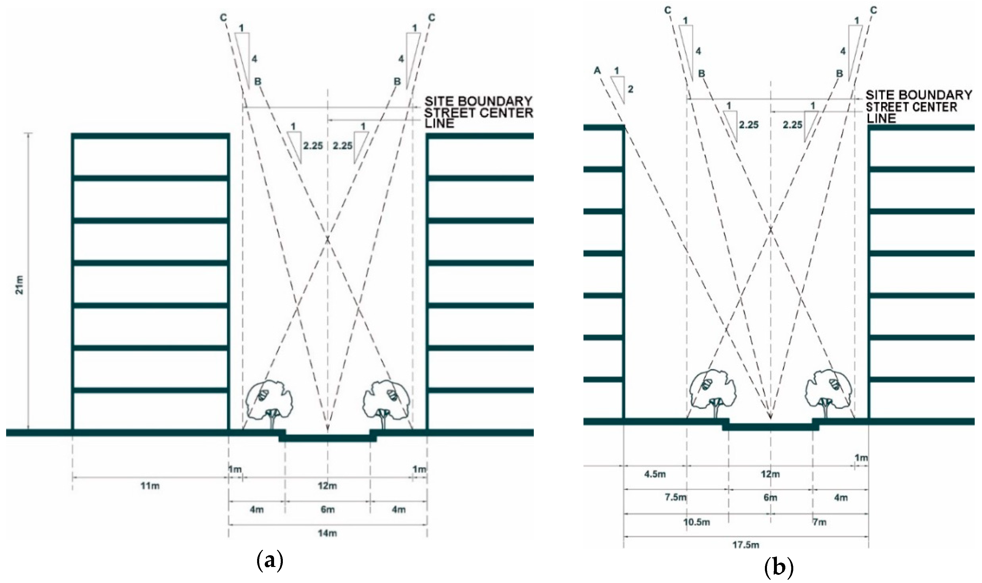
Figure 3.
(a) Simulation of Incident Solar Radiation of Living Room Balcony Window (b) Example of Ecotect Modeling Images of Street-Oriented Housing and Its Surrounding Conditions.
Figure 3.
(a) Simulation of Incident Solar Radiation of Living Room Balcony Window (b) Example of Ecotect Modeling Images of Street-Oriented Housing and Its Surrounding Conditions.

Figure 4.
(a) Self-shadow area (Red) and area to be removed (Blue) at Azimuth 0° (b) at Azimuth 60°.
Figure 4.
(a) Self-shadow area (Red) and area to be removed (Blue) at Azimuth 0° (b) at Azimuth 60°.

Figure 5.
Corner Mass Corner Adjustment at Azimuth 60°.

Figure 6.
Wind Patterns Changes between Buildings (From 3 m to 15 m).

Table 1.
Minimum Distance between Buildings for Day-lit conditions.
| Angle | Standard 1 | Standard 2 | Angle | Standard 1 | Standard 2 | ||||
|---|---|---|---|---|---|---|---|---|---|
| 0° | 36 m | 1.8 h | 36 m | 1.8 h | 0° | 36 m | 1.8 h | 36 m | 1.8 h |
| 15° | 35 m | 1.75 h | 35 m | 1.75 h | −15° | 34 m | 1.7 h | 35 m | 1.75 h |
| 30° | 27 m | 1.35 h | 34 m | 1.7 h | −30° | 25 m | 1.25 h | 31 m | 1.55 h |
| 45° | 25 m | 1.25 h | 30 m | 1.5 h | −45° | 17 m | 0.85 h | 30 m | 1.5 h |
| 60° | 14 m | 0.7 h | 30 m | 1.5 h | −60° | 14 m | 0.7 h | 33 m | 1.65 h |
| 75° | 15 m | 0.75 h | - | - | −75° | 14 m | 0.7 h | - | - |
| 90° | 14 m | 0.7 h | - | - | −90° | 15 m | 0.75 h | - | - |
Table 2.
Wind Velocity Ratio in relation to Opening shapes.
| Opening Location/Opening Height | 3 m | 6 m | 9 m |
|---|---|---|---|
 |  | ||
| Wind Velocity Ratio | 0.27 | 0.37 | 0.63 |
 |  | ||
| Wind Velocity Ratio | 0.23 | 0.37 | 0.46 |
 |  | ||
| Wind Velocity Ratio | 0.33 | 0.50 | 0.59 |
 |  | ||
| Wind Velocity Ratio | 0.26 | 0.26 | 0.41 |
Table 3.
Wind Velocity Ratio in relation to Mass Layout and Adjustment of Building height.
| Staggered Layout | Parallel Layout | |||
|---|---|---|---|---|
| Overall Height | Uniform Height | 10F (Second Row Building only) | Uniform Height | 10F (Second Row Building Only) |
| 3F |  |  |  |  |
| Ratio | 0.98 | 0.82 | 0.66 | 0.75 |
| 5F |  |  |  |  |
| Ratio | 0.79 | 0.65 | 0.65 | 0.70 |
| 7F |  |  |  |  |
| Ratio | 0.78 | 0.78 | 0.81 | 0.75 |
Table 4.
Mass Formation at Azimuth Angle of 0°.
| Mass Plan with Optimization of Daylighting/Daylight Hours (STD1/2) | ||
|---|---|---|
| Type 1 |  |  |
| F.A.R 234% | A1(4.1/4.1) A2(4/4) B1,B3(2.5/2.6) B2(2/2) | |
| Type 2 |  |  |
| F.A.R 239% | A1(0/0) B1(2/2) B2(2.5/2.6) | |
| Type 3 |  |  |
| F.A.R 212% | Refer to Table 6 for Daylighting Hours | |
| Type 4 |  |  |
| F.A.R 204% | Refer to Table 6 for Daylighting Hours | |
Table 5.
Mass Formation at Azimuth Angle of 60°.
| Mass Plan with Optimization of Daylighting/Daylight Hours (STD1/2) | ||
|---|---|---|
| Type 5 |  |  |
| F.A.R 211% | Y0(1.4/1.4) A(2.8/2.8) C(4.3/4.3) | |
| Type 6 |  |  |
| F.A.R 209% | A0(1.4/1.4) A1(2.9/4) A2(2.1/2.1) A3(2.4/2.4) B1(2/2) C1(2.2/3.2) C2(2.1/2.1) C3(2.9/2.9) | |
| Type 7 |  |  |
| F.A.R 228% | A(2/2) B1(2/2) B2(2/2) C(2/2) | |
Table 6.
Cluster Blocks Formation at Azimuth Angle of 0°.
| Mass Plan with Optimization of Daylighting/Daylight Hours (STD1/2) | |
|---|---|
 |  |
| Scheme 1A (Modification of Types 1 & 3) | A(3.3/3.3) B(3.7/3.7) C(2.5/3) W(3.3/3.3) X(2.5/2.5) Y(2/2) Z(2.5/3) |
 |  |
| Scheme 2A (Modification of 2 & 4) | A(4/4) B(2.8/2.8) C(2/2) D(2/2) W(5/6) X(4.5/5) Y(2/2) |
Table 7.
Cluster Blocks Formation at Azimuth Angle of 60°.
| Mass Plan with Optimization of Daylighting/Daylight Hours (STD1/2) | |
|---|---|
 |  |
| Scheme 3A (Modification of Type 5) | A(3/3) B(2.6/2.6) C(6/6) D(4.6/4.8) E(2/2) F(3/3) G(4.8/5.8) H(3.8/3.8) I(4/4) J(2/2) K(6/7) L(3.9/3.9) M(2.5/3) N(2/2) |
 |  |
| Scheme 4A (Modification of Type 6) | D(2/3) E(5/5) F(4/4) G(2/2) H(2/2) I(2/2) J(2/2) K(2.7/2.7) L(2.7/3.2) M(1+1.5/2.5) XO(1.4/1.4) YO(3.8/3.8) ZO(2/2) |
Table 8.
Wind Velocity Ratio in relation to Mass Layout and Adjustment of Bldg. Height (Scheme 1 Modified).
Table 8.
Wind Velocity Ratio in relation to Mass Layout and Adjustment of Bldg. Height (Scheme 1 Modified).
| Scheme 1A | Scheme 1B | |
|---|---|---|
| Basic Type |  |  |
| Wind Velocity Ratio | 0.406612 | 0.425273 |
| Lower Part Opening Type (_O) |  |  |
| Wind Velocity Ratio | 0.359322 | 0.461656 |
| Floor Height Adjust-ed Type (_12F) |  |  |
| Wind Velocity Ratio | 0.461691 | 0.559901 |
| Diagram of lower part opening |  |  |
| Axonometric View from North-east |  |  |
| Light Green: 3 m (H) opening, Green: 6 m opening, Orange: Height Adjustment | ||
Table 9.
Wind Velocity Ratio in relation to Mass Layout and Adjustment of Building Height (Scheme 2 Modified).
Table 9.
Wind Velocity Ratio in relation to Mass Layout and Adjustment of Building Height (Scheme 2 Modified).
| Scheme 2A | Scheme 2B | |
|---|---|---|
| Basic Type |  |  |
| Wind Velocity Ratio | 0.320784 | 0.470889 |
| Lower Part Opening Type (_O) |  |  |
| Wind Velocity Ratio | 0.433446 | 0.503587 |
| Floor Height Adjust-ed Type (_12F) |  |  |
| Wind Velocity Ratio | 0.620102 | 0.518342 |
| Diagram of lower part opening |  |  |
| Axonometric View from North-east |  |  |
| Light Green: Green: 6 m opening, Orange: Height Adjustment | ||
Table 10.
Wind Velocity Ratio in relation to Mass Layout and Adjustment of Building Height (Scheme 3 Modified).
Table 10.
Wind Velocity Ratio in relation to Mass Layout and Adjustment of Building Height (Scheme 3 Modified).
| Scheme 3A | Scheme 3B | |
|---|---|---|
| BasicType |  |  |
| Wind Velocity Ratio | 0.345048 | 0.485173 |
| Lower Part Opening Type (_O) |  |  |
| Wind Velocity Ratio | 0.455325 | 0.596659 |
| Floor Height Adjust-ed Type (_12F) |  |  |
| Wind Velocity Ratio | 0.575128 | 0.546359 |
| Diagram of lower part opening |  |  |
| Axonometric View from North-east |  |  |
| Green: 6 m (H) opening, Pink: 9 m opening, Orange: Height Adjustment | ||
Table 11.
Wind Velocity Ratio in relation to Mass Layout and Adjustment of Building Height (Scheme four Modified).
Table 11.
Wind Velocity Ratio in relation to Mass Layout and Adjustment of Building Height (Scheme four Modified).
| Scheme 4A | Scheme 4B | |
|---|---|---|
| Basic Type |  |  |
| Wind Velocity Ratio | 0.361419 | 0.499405 |
| Lower Part Opening Type (_O) |  |  |
| Wind Velocity Ratio | 0.420085 | 0.516752 |
| Floor Height Adjust-ed Type (_12F) |  |  |
| Wind Velocity Ratio | 0.434405 | 0.507568 |
| Diagram of lower part opening |  |  |
| Axonometric View from North-east |  |  |
| Green: 6 m (H)opening, Pink: 9 m opening, Orange: Height Adjustment | ||
© 2018 by the authors. Licensee MDPI, Basel, Switzerland. This article is an open access article distributed under the terms and conditions of the Creative Commons Attribution (CC BY) license (http://creativecommons.org/licenses/by/4.0/).
Share and Cite
MDPI and ACS Style
Kim, H.-J.; Kim, J.-S. Design Methodology for Street-Oriented Block Housing Considering Daylight and Natural Ventilation. Sustainability 2018, 10, 3154. https://doi.org/10.3390/su10093154
AMA Style
Kim H-J, Kim J-S. Design Methodology for Street-Oriented Block Housing Considering Daylight and Natural Ventilation. Sustainability. 2018; 10(9):3154. https://doi.org/10.3390/su10093154
Chicago/Turabian StyleKim, Ho-Jeong, and Jin-Soo Kim. 2018. "Design Methodology for Street-Oriented Block Housing Considering Daylight and Natural Ventilation" Sustainability 10, no. 9: 3154. https://doi.org/10.3390/su10093154
Note that from the first issue of 2016, this journal uses article numbers instead of page numbers. See further details here.