1. Introduction
Hydraulic works (dams, diversion dams, and dikes) can lead to major changes in the characteristics of river ecosystems. One of the most important negative impacts on the ichthyofauna is that they can create an insurmountable physical barrier impeding the natural movements of fish. Fish passage structures are designed to restore the longitudinal (downstream-upstream) connectivity of streams and rivers affected by such obstacles [
1], facilitating the passage of fish.
Fishway designs have traditionally been developed targeting salmonid species, to facilitate their passage during the migration period. Low passage efficiencies have been found in such devices for potamodromous species and other non-salmonid diadromous species [
2,
3,
4], with failure often attributed to the diversity in behaviours, morphology, physiological capacity, and swimming ability. Free movement of non-salmonid species is however crucial to sustain stocks in a moderately natural state and to maintain fish community structure and dynamics [
5]. The biological objectives of building a fish pass are thus developing towards allowing permanent free movement of the complete fish community [
6]. The introduction of temporary or permanent design modifications in existing fishways can be a solution to improve their efficiency for a wider range of species during the whole year, contributing to the achievement of this goal. A few studies have already shown the potential of retrofitting technical fishways as an economic solution for improving fish passage [
7,
8].
Pool-type fishways, which are the most common type worldwide [
9,
10,
11], consist of a channel with a sloping bed divided by cross-walls into a series of pools. The total height of the obstacle to surmount is divided into a number of small drops and suitable hydrodynamic conditions are recreated in the pools to facilitate the passage of fish. Vertical slot fishways (VSF) and deep slot fishways (DSF) are particular types of pool-type fishways, which differ on the type of connection between pools. They are both modular systems in which the opening that joins two successive pools is known as a slot. The slot is vertical when the opening extends all the way down the transversal wall, whereas the deep slot is the design where the opening is limited by a sill at its base.
The most straightforward advantage of DSF with respect to VSF is that they require a lower discharge to operate. The conversion of a VSF to a DSF, which requires minimal design modifications, can thus make for a more flexible design in inflow management, maintaining the correct operation of the fishway in periods of limited water availability. It is however crucial to understand the flow conditions that will be created inside the fishway, and their implications for fish passage.
Previous studies in VSFs have shown that the flow field is mainly two-dimensional, with nearly uniform velocities along the water column and small vertical velocities in comparison to the horizontal ones [
12,
13,
14]. The velocity fields in the pools are relatively insensitive to variations on the discharge, and the water depths are proportional to a dimensionless discharge with an almost linear relation. Two main flow regions can be distinguished: the recirculation regions characterized by low velocities, horizontal eddies and reversed flows; and the main flow region defined by a high velocity jet, where maximum velocities occur [
15].
The introduction of a sill at the base of the slot entails a change in the hydraulic characteristics of the flow. The sill may improve the orientation of the jet diagonally over the pool, thus avoiding short-circuiting from one pool to the next without the dissipation of an adequate proportion of kinetic energy of the flow [
10]. DSFs are associated with larger pool depths for a given discharge in the fishway [
16]; the height at which the sill is positioned makes it possible to increase or decrease the pool depths. The velocity field is also expected to be significantly different, with velocities being clearly three-dimensional in DSFs. It is essential to study these differences in order to evaluate the possible impact on the fish species that use these structures to overcome barriers.
The hydraulic conditions in the fishway must be compatible with the fish swimming capabilities and behavior [
17]. Extensive data on swimming performance are currently available for many species [
18], which can be compared to the velocity field developed in the fishway. It seems obvious that maximum water velocities must be less than the burst speed of the ascending fish. The majority of the flow velocity within the pools must also be below the species’ critical swimming speed, which has been often used to define the transition from the use of purely aerobic red muscle fibres to the recruitment of anaerobic white muscle fibres that result in muscle fatigue and oxygen debt [
19]. High vertical velocity components are also likely to influence the behavior of the fish, and can force them to shift from one depth to another [
6,
8]. On the contrary, low-velocity zones seem to play an important role, allowing fish to rest during upstream passage [
20].
Turbulence also affects fish swimming performance and behavior [
21]. Turbulence criteria have been incorporated into the design of pool-type fishways, typically through simple indicators of the average turbulent kinetic energy in the pools such as the volumetric power dissipation [
22,
23]. Recent studies have analyzed in more detail the fish response to turbulence parameters in fishways, with the aim of assessing the effect of potential key-variables that should be considered for future fishway designs. Their findings suggest that high turbulent kinetic energy can confuse fish in their efforts to move through the fishway along energy efficient paths, increasing fish fatigue [
24]. On the contrary, pool areas with low turbulent kinetic energy and Reynolds shear stress values can be used by fish for resting during the ascent though the fishway [
25,
26]. It should be noted, however, that fish response to variations of these parameters is still not well documented, and that other turbulence descriptors such as the eddy size and strength are also suspected to be important for effective fish passage [
27].
In this paper, the hydrodynamics of DSFs were studied experimentally. The objective was to investigate the feasibility of DSF as a retrofitting option to make existing VSF more suitable for fish passage during low flows. Two different basic pool configurations of VSF, reported to be effective by Rajaratnam et al. [
28], and previously studied by the authors [
12] were considered. A sill was positioned at the base of the slot, and five different sill heights were evaluated. The performance of the fishway was evaluated only in terms of hydrodynamics, and no experiments with fish were conducted. The experimental model study of the hydrodynamics of DSFs allowed us to acquire fundamental knowledge on the operation of this type of fishways. This is intended to contribute to the development of more effective fish passage structures, capable of accommodating all movements of a wide range of species and sizes of fishes.
2. Materials and Methods
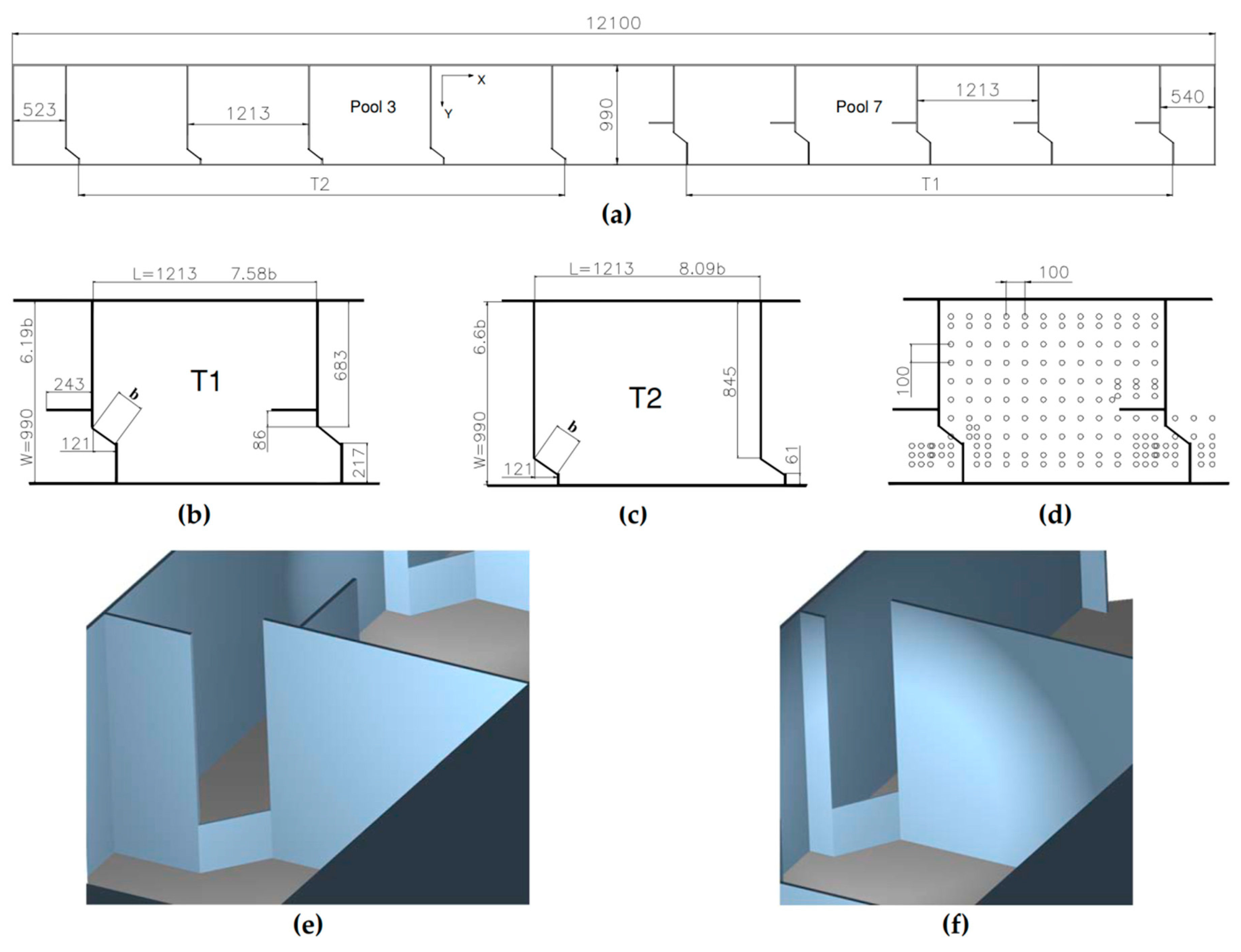
The experimental work was carried out at the CITEEC (Centro de Innovación Tecnolóxica en Edificación e Enxeñería Civil) at the University of A Coruña (Spain). The fishway scale model consisted of a metallic structure 12 m long, 10% slope and 1 × 1 m
2 rectangular section. The fishway was divided into eleven pools. The first four pools presented a T2 configuration, the next three were transition type pools and the last four had a T1 configuration (
Figure 1). The two pool designs differ in the dimensions and shape of the cross walls. In design T1, the left side cross-wall is shorter and has a baffle fixed to its upstream face, and the right side cross-wall is longer. The flume bed, side walls and the cross-walls (vertical) separating the pools were made of transparent methacrylate sheets making it possible to observe the flow. The experimental measurements were recorded in pools number 3 and 7 (
Figure 1a). Discharge was measured by means of an electromagnetic flowmeter. All the elements in the recirculating water circuit were automated and their operation was centralized in a control computer.
Uniform flow conditions [
13,
28,
29] were used in the tests, so that the mean depth measured at the middle transverse section (y
o) was the same in all the pools. At the lower end of the flume a tailgate causing overflow was used to reach the necessary boundary conditions for the uniform flow. For this reason, the tailwater levels were different for each discharge tested.
A traversing system was placed over the experimental pools to automate the positioning of the measurement instruments and could therefore be set automatically at any point in the pool. Two measurement devices—a depth probe and a velocimeter—were placed on the traversing system to perform the measurements. Velocities were measured by means of a Doppler Effect velocimeter (MicroAcoustic Doppler Velocimeter SonTek: San Diego, CA, USA). Through the MicroADV Data Acquisition System the velocity in the three Cartesian axes (Vx, Vy, and Vz) was obtained for each data point [
30,
31]. The water surface height in the pools was measured by means of a conductivity-based depth probe, DHI Wave Gauge Type 202. The instrument remained at each data point for 10 s to collect data on depth. The velocity data was measured at a frequency of 15 Hz during 15 s.
Velocity measurements were carried out in planes parallel to the flume bed with a separation of 10 cm between them, starting at 5 cm from the channel bed up to as close to the water surface as possible. In each plane, data points were distributed forming a 10 × 10 cm mesh, reduced to 5 × 5 cm in critical zones (
Figure 1d). Therefore a three-dimensional mesh of 10 × 10 × 10 cm was used to measure velocity. In each plane parallel to the flume bed, velocity was measured at 140 points in design T1 and at 132 points in design T2. The number of parallel planes ranged from 2–8 depending on the discharge and sill height. A summary of the experimental measurements obtained is presented in
Table 1. Depth measurements in the pools were evaluated using a two-dimensional mesh with points at a 10 × 10 cm maximum separation in between. Depth was measured at 111 and 109 points in designs T1 and T2, respectively.
The experimental survey is summarized in
Table 1. Five different sized sills were tested in each pool design (T1 and T2). The range of discharges used for each sill varied from the minimum discharge needed to use the measuring instruments up to the maximum discharge achievable in the laboratory model.
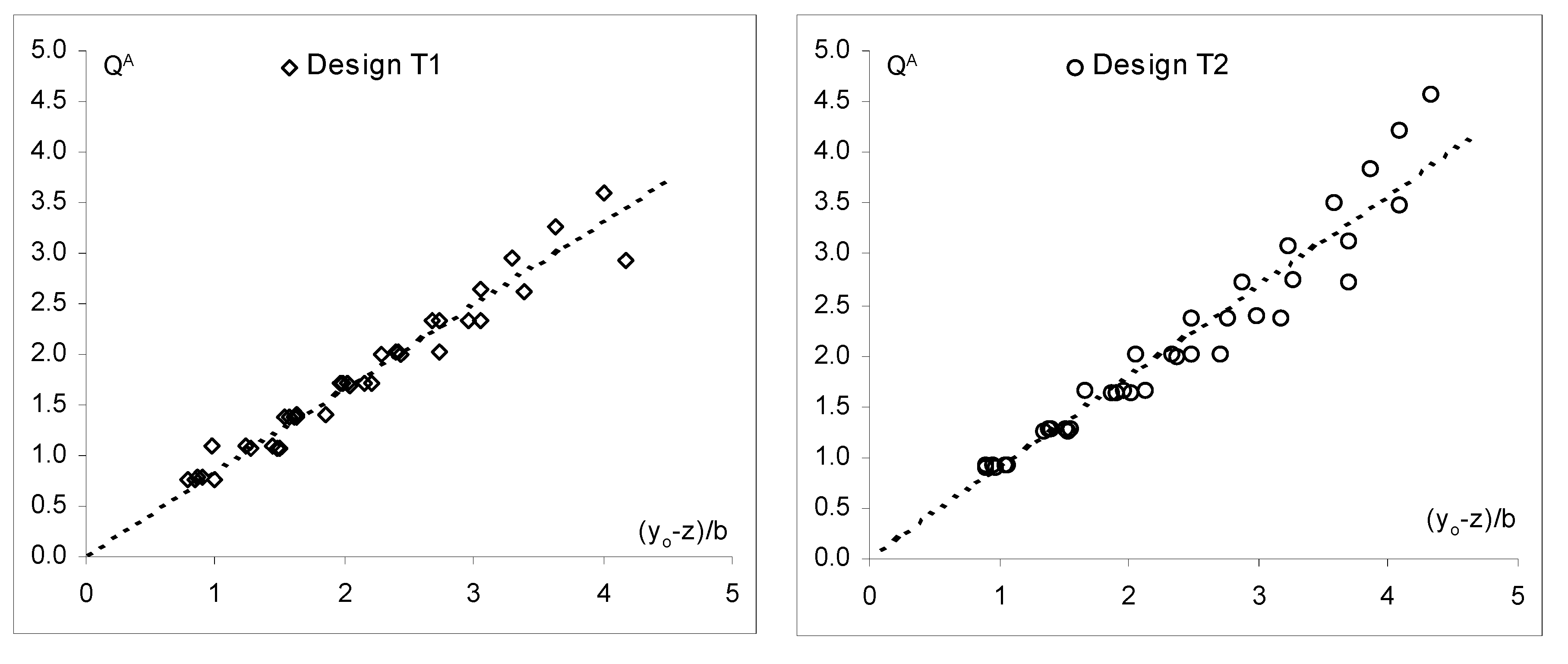
The hydrodynamics of a DSF depend upon the discharge (Q), the geometric slope (S), the slot width (b) and the sill height (z). From the dimensional analysis, the following dimensionless variables were chosen for the representation of the experimental results: , yA = (y – z)/b. The variable QA is the dimensionless discharge and yA is the relative flow depth. The variable y represents the depth measured at any given point in the pools. The following characteristic depths were defined: the mean depth at the transverse middle section of the pool (yo), the depth at the slot measured from the lower sill base (yb), the mean depth in the pool (ym), and the maximum and minimum depths in the pool, (ymax and ymin, respectively).
In order to quantify the turbulence generated in the DSFs, two key turbulent variables were selected: the turbulent kinetic energy k, calculated as , where are the variance of the fluctuation velocity in each spatial direction; and the turbulence intensity Ikt, defined as , where is the mean velocity. It should be noted that the temporal resolution of the velocity measurements would not allow us to perform other types of analysis such as the calculation of the power spectrum.
4. Discussion
This study analyzes the hydrodynamics of DSFs for two different pool configurations and five different sill heights, using a laboratory physical model. The experimental results included the data obtained in the VSFs, considering this type of fishway as a special case of DSFs in which sill height is zero. The inclusion of these data allowed us to compare the two types of fishways in addition to providing us with a more generalized view of these structures. Further details on the characteristics of the flow field developed in the two VSF designs can be found in the work of Puertas et al. [
12].
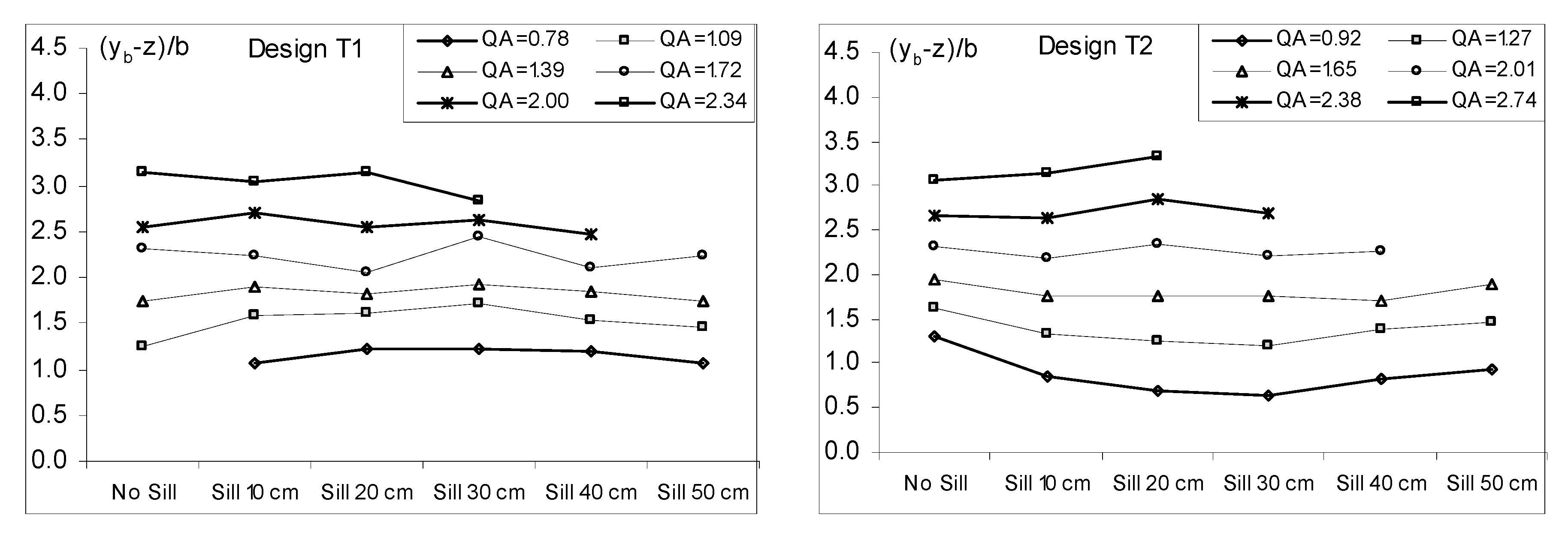
Retrofitting of VSFs by adding a sill across the slot can be a solution to maintain adequate water depths for fish swimming during low flows. For the same discharges, the addition of a sill results in an increase in depth proportional to its height, while still allows fish to swim rather than leap over obstacles. Design T2 has a greater flow conveyance efficiency than design T1, which means that for the same discharge a lower depth is obtained (and consequently a higher velocity). In the extreme case in which the sill blocks most of the slot (very large sill height), the connection between pools is, effectively, a submerged notch operating in a streaming regimen [
32]. In fact, the regimen in VSFs is sometimes referred to as streaming flow by analogy with these pool-type designs [
33]. In laboratory experiments under controlled conditions, this flow regime has been found to enhance fish movements through surface notches, increasing the negotiation success of several species with different ecological characteristics, such as the Iberian chub [
34,
35] or the Iberian barbel [
34,
36]. Although further research is needed, these findings suggest that this flow regime favors multi-species fish passage, which can be considered an advantage of DSFs compared to other pool-type designs.
Unlike VSFs, the addition of the sill in DSFs prevents bottom dwelling species from swimming at their desired depth when passing through the slot. VSFs, which offer the full range of depth for passage, or pool-type fishways with submerged orifices would be preferable for these species, because of their preference for swimming close to the bottom. Moreover, the flow is no longer two-dimensional and flow conditions differ considerably along the vertical direction. This could also potentially contribute to different passage efficiencies of bottom-oriented and water-column species. In the lower planes (below the sill elevation), velocity and turbulence levels are low, and fish could find suitable resting areas to recover after negotiating the slot. On the contrary, fish face more challenging hydraulic conditions in the upper region of the pools (above the sill elevation). Maximum velocities are in the same order of magnitude as in the corresponding VSFs, but the three-dimensionality of the flow increases. High vertical velocity components, which only occurred in the slot region in VSF designs, are likely to influence the behavior of the fish [
6]. Ascending velocities can disturb the fish behavior by generating a secondary flow that may force fish to shift from one depth to another [
8]. Fish might move up in the water column, encountering less favorable hydraulic conditions.
Turbulence increases with respect to VSFs in this upper portion of the pools, which can also affect fish locomotion [
21,
37]. The highest turbulent kinetic energy values, both averaged over the horizontal plane and point values, are obtained in the planes higher than the sill level, showing a certain degree of coupling with the velocity fields. High turbulent kinetic energy can confuse fish in their efforts to move through the fishway along energy efficient paths, increasing fatigue [
24]. In order to allow fish to rest, the pools should also provide large areas of low turbulent kinetic energy values (<0.05 m
2/s
2) [
25]. In the designs tested, such areas would only be available in the lower portion of the pools, which would force fish to move vertically to find them. It should be noted, however, that the effect of turbulence on fish passage is still in the early stages of investigation, and other variables such as the Reynolds shear stress and eddy size are also suspected to be important in explaining fish swimming behavior [
27]. Their effect is however likely to differ widely among species, and even among individuals within a species [
38].
Thus, for further research, it would be useful to deepen the characterization of turbulence in DSFs, calculating additional descriptors that might correlate with fish response. Due to the high number of velocity measurements performed in this study, a relatively short measurement period was used. The experimental survey could be extended considering a more limited number of representative discharges and DSFs configurations, identified based on the results of this work. For these representative cases, longer time series of instantaneous velocity could be measured in order to increase the accuracy of the calculated turbulence descriptors. It would be also interesting to increase the ADV sampling frequency, in order to allow the analysis of inertial and dissipation subranges of the power spectrum.
Considering the potential implications for fish passage, it is necessary to conduct experiments with fish in order to study how hydraulic conditions in DSFs can affect fish passage. Given the variability in swimming performance, behavior and niche occupancy between species, several species representative of different morpho-ecological groups should be tested, similarly to what has been recently done for other fishway designs [
34]. The findings suggest that the DSFs designs could be more species selective than VSFs, and therefore not appropriate for facilitating passage for a wide range of fish species. This would require exploring alternatives to reduce fishway selection, such as introducing operational changes that take advantage of temporal differences in movement patterns between species [
39]. A potentially higher passage difficulty in DSFs would lead to a compromise between improved functionality of VSFs during the low-flow season, and potentially lower passage rates outside this season. If this were the case, the use of temporary modifications (e.g., removable sills) could be the way forward to improve the efficiency of the fishway during the whole year.
5. Conclusions
A wide variability was observed in the water circulation patterns of DSFs, depending on the cross-wall design, the sill height and the circulating discharge. The flow established was clearly three-dimensional, unlike that developed in VSFs. An uneven distribution of turbulent kinetic energy in the pools at different heights was found. The complexity of the flow obliges fish to tackle a three-dimensional water circulation with highly turbulent areas.
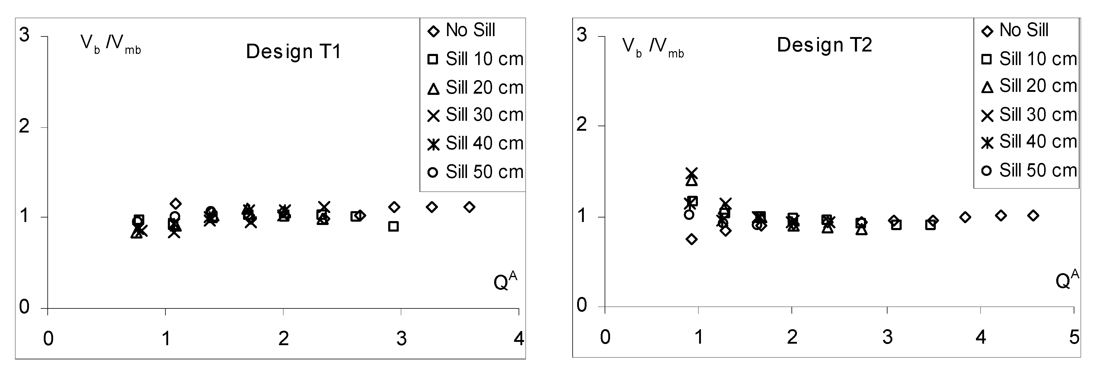
The discharge relationships that relate discharge and depth were calculated for both pool designs. Design T2 was verified to have greater flow conveyance efficiency, so given the same design discharge, the depths would be lower in this design. The use of different sill heights at the base of the slot makes inflow management more flexible. An increase in the sill height translates to a proportional increase in depth. However, the water height above the sill at the slot remains relatively constant regardless of the sill height used. The invariance of the velocity at the slot against the discharge and height over the flume bed was demonstrated. The velocities in design T2 were higher than in design T1.
The results show that retrofitting a VSF by adding a sill at the base of the slot might improve its functionality during low flows, ensuring adequate water depths for fish swimming. However, given the complexity of the flow developed in DSFs, further research is needed to evaluate the fish response to these challenging hydrodynamic conditions.


