Article

Prediction of the Heights of the Water-Conducting Fracture Zone in the Overlying Strata of Shortwall Block Mining Beneath Aquifers in Western China

1
State Key Laboratory of Coal Resources & Safe Mining, School of Mines, China University of Mining & Technology, Xuzhou 221116, China
2
State Key Laboratory for Geomechanics & Deep Underground Engineering, China University of Mining & Technology, Xuzhou 221116, China
*
Authors to whom correspondence should be addressed.
Sustainability 2018, 10(5), 1636; https://doi.org/10.3390/su10051636
Submission received: 24 April 2018 / Revised: 10 May 2018 / Accepted: 15 May 2018 / Published: 18 May 2018
(This article belongs to the Section Energy Sustainability)

Abstract

:
Longwall mining leaves pillars and irregular blocks of coal behind in its aftermath. In this study, a shortwall block mining (SBM) technique for recovering these coal resources has been proposed. A mechanical analysis model for calculating the heights of the water-conducting fracture zone (HWFZ) in overlying strata of SBM was established based on the theory of beams on elastic foundations. Using this model and the data acquired from a working face in the experimental area, a height of 50.30 m was calculated for HWFZ corresponding to this working face. This observation indicates that the equation for predicting HWFZ in working faces specified by the Hydrogeological Procedures for Mines (HPM) standard is not suitable for application in SBM. For this reason, the Universal Distinct Element Code (UDEC) modeling program was used to analyze the developmental behavior of the water-conducting fracture zone under various determining factors in SBM. The UDEC simulations indicated that the HWFZ increase linearly with an increase in mining height, decrease linearly with an increase in the width of the protective coal pillars, and increase logarithmically with block length. A nonlinear regression analysis of HWFZ was performed using the SPSS software suite, from which a model for predicting HWFZ in SBM was constructed. This model predicted that the HWFZ was 52.58 m in the experimental area, while field measurements yielded HWFZ values varying from 47.98 to 50.06 m, which was basically consistent with the results of the prediction model and the mechanical model, thus confirming the accuracy of the mechanical model and the reliability of the regression model. The results of this study will provide critical practical references for the enhancement of coal recovery rates in mining areas and enhance theories on aquifer protection during mining operations.

1. Introduction

The focal point for coal mining in China has shifted from eastern China to western China owing to massive coal reserves in the west. The coal reserves in these regions generally occur as shallow-lying coal seams buried at depths ranging from 100 to 200 m, with simple geological structures and high-quality coal. The mining technologies in these regions are also highly advanced [1,2,3,4]. However, western China is a semi-arid region with scarce water resources, sparse vegetation, and fragile ecological environments. In recent years, an increase in the number of mines and large-scale high-intensity mining in western China has resulted in significant losses of water resources and an exacerbation of desertification [5,6,7,8,9,10] (see Figure 1 [11]). Furthermore, significant quantities of coal have been left unmined in the form of coal pillars and irregular coal blocks [12,13,14]. The loss of water resources and the waste of coal resources not only disturb the production, life of the local people, and social stability, but also bring serious troubles to the sustainable development strategy of the government.
To address the issue of residual and discarded coal resources, this study proposes their recovery using the shortwall block mining (SBM) technique. The SBM technique is used to recover coal resources that are not suitable for extraction via longwall mining, and to reduce the damage range of overlying strata by retaining the protective coal pillars. Compared to conventional room mining, this technique has an enhanced resource recovery rate and integrates the excavation and mining of a working face, which substantially increases its efficiency [14,15]. A few of the relevant studies on SBM include the following: Zhou et al. [14,16] systematically studied the behavior of rock pressures during SBM based on the stress of coal pillars and roof movements. Cao et al. [15] analyzed the mechanism underlying abrupt instabilities in protective inter-block coal pillars during SBM from the perspective of cusp catastrophe theories. Mining processes will nonetheless result in movements and damage in the overlying strata, resulting in the formation of water-conducting fractures; further losses in water resources then occur if the water-conducting fractures develop and come into contact with aquifers or water-rich areas on the surface [17,18,19,20,21,22,23]. However, there are very few theoretical studies on the developmental behavior of the water-conducting fracture zone that are caused by SBM. Hence, there is an urgent need to investigate this issue. The predictive equation specified by the Hydrogeological Procedures for Mines (HPM) [24] standard is widely used to calculate the heights of the water-conducting fracture zone (HWFZ) caused by mining processes. Nonetheless, the unique layout of SBM operations necessitates further investigation to clarify whether the HPM standard’s empirical equation is appropriate for describing these cases.
The objective of the study is to predict HWFZ in SBM. Based on the characteristics of the SBM process, the present authors have put forward the factors that determine HWFZ and constructed a mechanical analysis model for calculating HWFZ caused by SBM by taking into consideration the damage characteristics of the overlying strata. This model was then used to evaluate the applicability of the HPM standard’s predictive equation. An investigation was performed on the developmental behavior of the water-conducting fracture zone in SBM using the Universal Distinct Element Code (UDEC) numerical modeling program. Multiple nonlinear regression analysis was used to fit the results of the simulations and derive a model for predicting HWFZ in SBM. Field verifications of this model were then performed. The observations of this research are likely to play a highly critical role in the recovery of coal resources, the enhancement of water resource protection measures during mining operations, and the protection of ecological environments.

2. Engineering Background and Shortwall Block Mining (SBM) Process

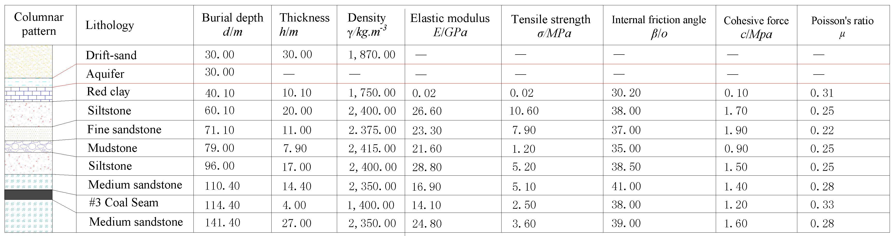
2.1. Engineering Background

The experimental area of SBM in Inner Mongolia is located in Ordos City, the surface of the area is covered with eolian sand, and the surface rivers and lakes do not exist in the surrounding area. With serious soil erosion, sparse vegetation, and a fragile ecological environment, there is an aquifer in the underground above the red clay, and the area belongs to the typical semi-arid and semi-desert climate, which displays strong seasonality. The experimental area of SBM has an area of 32,400.00 m2 and 93,000.00 t of estimated recoverable coal reserves. The working face mainly extracts coal from the #3 coal seam, which is a flat-lying coal seam with a simple and stable structure and relatively minute variations in thickness. Its average burial depth is 110.00 m, and its thickness is approximately 4 m. The roof of the coal seam is composed (from the bottom to the top) of medium-grained sandstones, siltstone, mudstone, fine sandstone, Hipparion red clay, and drift sand. An aquifer lies above the red clay stratum at approximately 80.00 m from the coal seam; loss of groundwater is highly likely if the water-conducting fractures in the overlying strata reach the aquifer. The columnar pattern and mechanical parameters of the mining area are presented in Figure 2.
Coal recovery was performed in two blocks—each with a mining height of 4.00 m—in the experimental area. The length of each block was approximately 70.00 m, and the protective coal pillars between the blocks were approximately 10.00 m wide. The design of the working face is illustrated in Figure 3.

2.2. SBM Processes

The main purpose of the SBM technique is to recover coal resources that are not suitable for extraction via longwall mining. In the working face for SBM, bolts, mobile roof supports, and preserved coal pillars are used to support the roof [14]. These techniques integrate excavation and mining operations, are highly automated and flexible, require minimal upfront investment, and can be rapidly deployed, which substantially enhances the recovery rate of a mine.
(1) The technical system for SBM
A classic technical system for SBM and the layout of the working face is illustrated in Figure 4. The recovered coal is transported in the following order: working face of SBM → haulage roadway of SBM → main haulage roadway → main shaft; the material transport system has following order: auxiliary shaft → track haulage roadway → track haulage roadway of SBM → working face. A mining block is formed through the installation of four branch roadways and three connecting roadways, and a protective coal pillar is set between each block. The coal pillars in each block are recovered from the top to the bottom, in retreating fashion. Based on the stability of the roof, each block was designed with an approximate length of 70.00 m, while the protective pillars between the blocks had a width of approximately 10.00 m.
(2) Main Equipment and Working Face Parameters
The most critical pieces of equipment for SBM include mobile roof supports and continuous miners. During the recovery of coal pillars, a temporary coal pillar is left between each mining cave, which acts in unison with four mobile roof supports to ensure that the continuous miners are able to safely complete their coal cutting and loading processes. The layout of the mobile roof supports is displayed in Figure 5, which shows that the supports were separated into two groups (Supports 1 and 2 formed one group, while Supports 3 and 4 formed another group), with one group placed in the branch roadways and the other group placed in the connecting roadways between two adjacent branch roadways. The width of the branch and connecting roadways was 5.00 m. The length of the mining caves was less than 11 m, while their width was 3.30 m, and the angle between the mining cave and branch roadways was approximately 45°, with a 0.5–1.5 m gap left between each cut to form coal pillars between the mining caves.

3. Mechanistic Analysis of the Development of Water-Conducting Fracture Zone during SBM

It is imperative that water-conducting fractures are prevented from reaching an aquifer when coal is mined from deposits lying beneath aquifers. The most widely applied method for predicting HWFZ in China is the predictive equation given in the HPM standard, but this equation was derived from regression calculations based on limited field measurement data from mining done in China during the early 80 s. Both SBM and longwall mining use caving techniques to manage the roof, and thus display similar behaviors and mechanisms in their roof fractures, ground pressure, and fractures development [25]. Nonetheless, the predictive equation given in the HPM standard was based on measurements made in longwall mining, whereas the layout of the working face in SBM is quite different from that of longwall mining. Therefore, further investigation is required to elucidate whether the HPM standard’s empirical equation based on longwall mining is applicable in SBM.

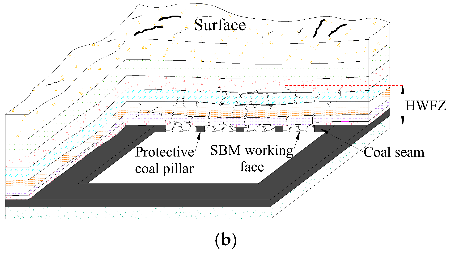
3.1. Characteristics of Overlying Strata Damage in SBM

(1) Conventional longwall caving methods
In conventional mechanized coal mining, the immediate roof of mined-out areas collapses under the action of its own weight and that of the overlying strata as the working face progresses forward. In turn, the main roof also collapses, ultimately causing fractures in key strata that subsequently result in surface subsidence. The coal mining processes in shallow-lying coal seams in western China in particular are likely to cause highly adverse “step” subsidence, which results in elastic damage over a wide area [26]. The characteristics of overlying strata displacements in conventional mechanized longwall mining are illustrated in Figure 6a.
(2) SBM
In the SBM process, protective coal pillars are preserved between adjacent blocks as the working face progresses and causes caving along the way. The coal pillars support the load of the overlying strata, which substantially reduces the damage inflicted on the main roof and the overlying strata above it, thus restricting the development of the water-conducting fracture zone. The characteristics of deformation in rocks surrounding SBM are illustrated in Figure 6b.

3.2. Determining Factors of HWFZ in SBM

The determining factors of HWFZ in SBM were obtained through comparisons based on the characteristics of overlying strata damage and the layout of working faces in SBM, as illustrated in Figure 7. These factors include the following:
(1) Mining height
Mining height is one of the most critical factors that determine the range of damage in overlying strata [27]. After a volume of coal has been recovered, the surrounding stresses of the goaf redistribute themselves and locally induce concentrations of stress that result in bedding fractures. Varying mining heights in the working face results in varying heights in the “three zones” (caved, fractured, and continuous zones) developed within the overlying strata [2,28,29]. Furthermore, the empirical equation in the HPM standard for predicting HWFZ implies that mining height is the only factor that determines HWFZ.
(2) Width of the protective coal pillars
The preservation of protective coal pillars plays a critical role in regulating overlying strata movements and maintaining the stability of rocks surrounding a mine as these pillars bear the combined rock load over the goafs and coal pillars [30]. Under certain conditions, the load capacity of the coal pillars is determined by their dimensions; hence, the design of the protective pillars has a substantial determining effect on the regulation of damage in the overlying strata and HWFZ.
(3) Length of the block
Similar to the mining height, the length of the block is one of the parameters of the working face that determine HWFZ. This is reflected in the fact that the length of the excavation has a direct effect on plastic damage, deformations, and stress redistributions in the overlying strata.
(4) Mining depth
Based on rock mechanics theories [31], ground stresses increase as the depth increases, and varying coal mining depths result in varying levels of stress in the surrounding rocks of a working face. Therefore, the mining depth also affects the range of overlying strata damage to a certain extent.
(5) Structural geology
Different geological structures not only directly affect the movement law of overlying strata, but also the characteristics of surrounding rock stress distribution and the shape of ground subsidence after the working face was mined out. The thickness, lithology, location, stability, etc., of each rock stratum will lead to a different range of development of the water-conducting fracture zone.
It is not feasible to alter the mining depth and structural geology for a specified geological setting. Therefore, regulation of the water-conducting fracture zone is to be accomplished through the rational design of key technical parameters such as mining height, block length, and width of protective coal pillars, in order to ensure that losses in water resources do not occur as a result of the growth of water-conducting fractures.

3.3. The Construction of a Mechanical Model and the Analysis of Bending Deformations

(1) Construction of a mechanical model for calculating HWFZ
HWFZ were determined from the height of the failed strata above the working face based on the factors that determine HWFZ in SBM. Here, an arbitrary stratum above the coal seam (denoted as the ith stratum) is considered as the subject of study, and the loads above this stratum are simplified as q1(i), q2(i), and q3(i), as illustrated in Figure 8. Suppose that the thicknesses of the strata above the coal seam are h1, h2, h3, ..., hm, the total thickness of the rock composed of i strata lying above the coal seam is H i = h k ( i = 1 , 2 , 3 , , m ) .
Figure 8 shows that the actions of the strata and coal beneath the ith stratum on rock beams of the ith stratum can be simplified using Winkler’s model for elastic foundations [32,33]. The location of the starting cut, O, was set as the origin, the direction of the working face’s progression was set as the x-axis, and the direction of the displacement function wi(x) was set as the y-axis. The resulting mechanical model for calculating HWFZ is illustrated in Figure 9. The length of each block is l1, and the width of the protective pillars between each block is l2. Here, the effects of factors such as the coal pillars between the mining caves in the mine and time have not been considered.
In particular, the uniformly distributed load that an arbitrary stratum above the rock beams bears may be expressed as:
{ q 1 ( i ) = γ ( d H i 1 ) ,   load   above   coal   seam q 2 ( i ) = γ ( d H i 1 ) ,   load   above   goaf q 3 ( i ) = j γ ( d H i 1 ) ,   load   above   protective   coal   pillar
In this equation, γ is the bulk density of the rocks, d is the burial depth, d’ is the potential caving height, and j is the stress concentration coefficient. The elastic foundation coefficients, ki, of the coal seam and the (i-1)th strata above the seam are expressed as:
1 k i = 1 k c + 1 k 1 + 1 k 2 + 1 k i 2 + 1 k i 1
In this equation, kc is the elastic foundation coefficient of the coal bodies, while k1, k2, k3, ..., ki-1 are the elastic foundation coefficients of each stratum.
(2) Analysis of bending deformations
Based on the theories of rock beams on elastic foundations [34,35,36], the deflection wi(x) of rock beams in the ith stratum of the mine and the loading on the rock beams should satisfy the fundamental differential equations for the deflection curves of beams on a foundation, in which n is the number of mining blocks. Hence, the differential equations of the deflection curves of rock beams in an arbitrary stratum of the overlying strata are:
{ E I d 4 w 1 i ( x ) d x 4 + k i w 1 i ( x ) = q 1 ( i ) ( x 0 ) E I d 4 w 2 i ( x ) d x 4 = q 2 ( i ) ( 0 x l 1 ) E I d 4 w 3 i ( x ) d x 4 + k i w 3 i ( x ) = q 3 ( i ) ( l 1 x l 1 + l 2 ) E I d 4 w 2 n i ( x ) d x 4 = q 2 ( i ) ( ( n 1 ) ( l 1 + l 2 ) x n l 1 + ( n 1 ) l 2 ) E I d 4 w 2 n + 1 i ( x ) d x 4 + k i w 2 n + 1 i ( x ) = q 1 ( i ) ( x > n l 1 + ( n 1 ) l 2 )
In these equations, EI is the flexural rigidity of a beam section, while n is the number of blocks.
A characteristic coefficient is defined as α = k i 4 E I 4 , and the deflections of an arbitrary stratum are introduced. This yields the equations for the deflection curves of each segment above the beams, as illustrated below:
{ w 1 i ( x ) = e α x ( A 1 cos α x + B 1 sin α x ) + e α x ( C 1 cos α x + D 1 sin α x ) + q 1 ( i ) k i ( l 2 2 x 0 ) w 2 i ( x ) = q 2 ( i ) x 4 24 E I + A 2 x 3 6 + B 2 x 2 2 + C 2 x + D 2 ( 0 x l 1 ) w 3 i ( x ) = e α x ( A 3 cos α x + B 3 sin α x ) + e α x ( C 3 cos α x + D 3 sin α x ) + q 3 ( i ) k i ( l 1 x l 1 + l 2 ) w 2 n i ( x ) = q 2 ( i ) x 4 24 E I + A 2 n x 3 6 + B 2 n x 2 2 + C 2 n x + D 2 n ( ( n 1 ) ( l 1 + l 2 ) x n l 1 + ( n 1 ) l 2 ) w 2 n + 1 i ( x ) = e α x ( A 2 n + 1 cos α x + B 2 n + 1 sin α x ) + e α x ( C 2 n + 1 cos α x + D 2 n + 1 sin α x ) + q 1 ( i ) k i ( x > n l 1 + ( n 1 ) l 2 )
The foundation coefficient is related to the thickness of the coal seam by the following equations [37]:
{ k c = E c / h c k i = E i / h i
Here, Ec is the elastic modulus of the coal bodies, Ei is the elastic modulus of an arbitrary stratum, and hc is the mining height.
The boundary conditions of the beams are as follows:
{ θ 1 i ( ) = 0   w 1 i ( ) = 0 θ 2 n + 1 i ( + ) = 0   w 2 n + 1 i ( + ) = 0
Continuity condition: The deflections, bending moments, corner angles, and shear forces of the coal pillars, stope, and coal seam are equivalent at their points of connection.
The introduction of boundary and continuity conditions yields the following parameters to be solved: A1, B1, C1, D1, A2, B2, C2, D2, ..., A2n+1, B2n+1, C2n+1, D2n+1. With these parameters, the equations for the roof’s bending and subsidence, wi(x), and the bending moment, Mi(x), are obtained.

3.4. Calculating of HWFZ

The maximum tensile stress of a beam according to the theory of beams with rectangular sections is:
σ max i = | 6 M max i h i 2 |
In this equation, σimax is the maximum stress of an arbitrary stratum in the overlying strata, and Mimax is the maximum bending moment in an arbitrary stratum of the overlying strata.
Based on the maximum normal stress theory, if a stratum fails, the following equation should be satisfied:
σ max i [ σ i ]
In this equation, [σi] is the tensile strength of an arbitrary stratum of the overlying strata.
The analysis here begins from the first stratum above the coal seam; if this stratum satisfies Equation (7), the stratum will fail and water-conducting fractures will then occur. Then, the adjacent upper strata will continue to be checked until the calculation is stopped when a stratum does not fail. HWFZ is then the sum of the thicknesses of the failed strata, and its value is:
H i = h 1 + h 2 + h 3 +
The predictive equation H = 100 m 3.3 n + 3.8 + 5.1 in Appendix 7 of the HMP standard (m being the mining height and n being the number of mined strata) yields an HWFZ of 75.50 m based on the mechanical parameters of the strata illustrated in Figure 2. The calculation based on mechanical theories, however, yields an HWFZ of 50.30 m. These outcomes indicate that the prediction by the HMP standard’s predictive equation varies substantially from the results of the analysis using the mechanical model. This reveals that the empirical equation in the HMP standard is not effective in predicting HWFZ in SBM.

4. Methods for Predicting HWFZ in SBM

4.1. Procedure for Designing a System that Predicts HWFZ in SBM

As the HMP standard’s predictive equations are determined to be inaccurate in the prediction of HWFZ in SBM, a system for predicting HWFZ in SBM had been established according to the characteristics of the previously described SBM processes and the mechanical analysis of the developments pattern of the water-conducting fracture zone. UDEC numerical simulations were performed based on the geological characteristics of an actual mine and its area of recovery, and single factor analyses were performed for determining factors such as mining height, width of the protective pillar, and block length, to obtain HWFZ corresponding to varying sets of conditions. Finally, a multiple nonlinear regression analysis was used to complete the construction of the prediction model for HWFZ, and the procedure for its design is described in Figure 10.

4.2. Numerical Simulation Studies of HWFZ in SBM

The predictive equation in the HMP standard was derived using empirical methods, in which a limited set of field measurement data on HWFZ in working faces were analyzed. During this analysis, the effects of the physical and mechanical properties of the overlying strata on damage and deformation were not taken into consideration. The method for determination used in the analysis, which was based on mechanical theories, was conservative and not capable of accurately calculating HWFZ in rock layers that have suffered damage, and the mechanistic model could not calculate HWFZ caused by the local failure of a stratum. The UDEC analytical software uses the discrete element method based on rock mechanical theories, as well as the lithology and parameters of the various strata; this method is thus capable of simulating the range of plastic damage in strata with a substantially high level of accuracy and overcoming the deficiencies of the HMP standard’s predictive equation and mechanical calculation [38,39].
Based on the geological conditions of the experimental area, the UDEC modeling program was used to study the developmental behavior of the water-conducting fracture zone during SBM. The construction of the numerical model is illustrated in Figure 11. Both sides of the model were constrained to horizontal displacements, while the bottom of the model was constrained to vertical displacements. The Mohr–Coulomb model was used to add an evenly distributed 0.56 MPa load on the top of the model. The fundamental length and height of the model were 270.00 × 111.00 m, and 50.00 m margins were dug out on each side of the model. Mesh refinement was performed on the strata in the vicinity of the coal seam, taking into account both the accuracy of the calculations and computational time.
To study the state of development of the water-conducting fracture zone with various mining heights, block lengths, and protective coal pillar widths, three simulation cases were designed, as presented in Table 1. The simulation cases in Table 1 were determined according to the key factors that affect the development of the water-conducting fracture zone during SBM, engineering geological conditions of Figure 2, preliminary design parameters of the experimental area in Figure 3, and related empirical design parameters in SBM. The physical and mechanical parameters of the coal seam and the various strata in the numerical model were based on rock mechanics data measured in a laboratory (as illustrated in Figure 2).
The results of the numerical simulations are as follows:
(1) HWFZ with varying mining heights
Based on the analysis illustrated in Figure 12, HWFZ increased linearly with mining height (when the width of the protective coal pillars and the length of the blocks were kept constant). HWFZ was 45.00 m when the mining height was 2.00 m, and it developed to 53.00 m when the mining height was 4.00 m. Hence, it is shown that increases in mining height promote the development of the water-conducting fracture zone.
(2) HWFZ with various protective coal pillar widths
The analysis in Figure 13 indicates that the width of the protective coal pillar was inversely correlated with HWFZ when the mining height and block length were kept constant. The amplitude of the curve’s decline is uniform and approximates a straight line. Hence, it is demonstrated that a sufficiently protective coal pillar width is a prerequisite for suppressing the growth of the water-conducting fracture zone.
(3) HWFZ with various block lengths
From Figure 14, it is evident that HWFZ increased with an increase in block length, albeit at a decreasing rate of increase, such that HWFZ appears to be a logarithmic function of block length. HWFZ increased rapidly when the block length ranged between 50.00 and 60.00 m; however, it attained a plateau (and stabilized) when the block length ranged from 60.00 to 80.00 m. Hence, reasonable adjustments of block length directly affect the regulation of overlying strata movements and HWFZ.
(4)
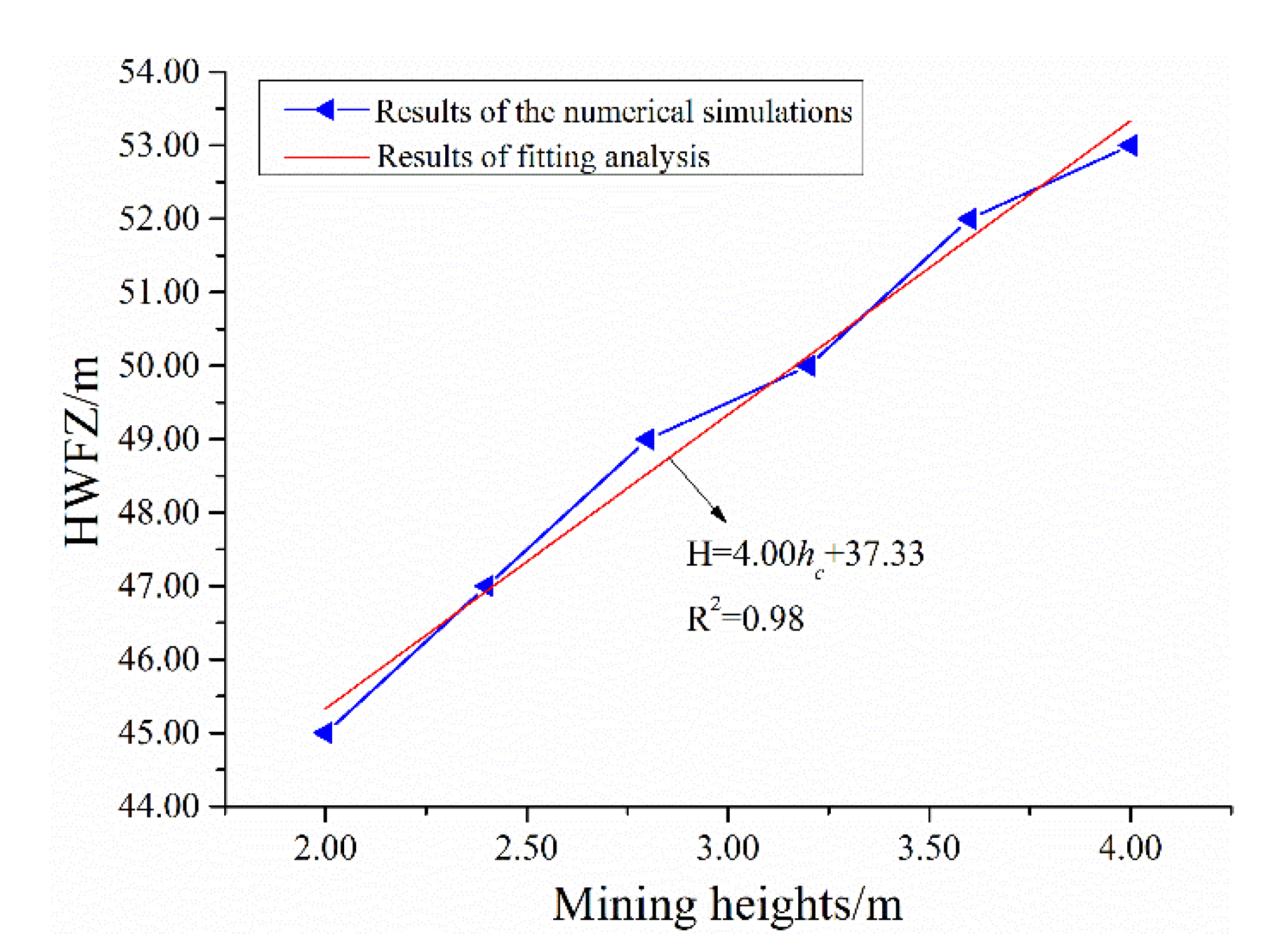
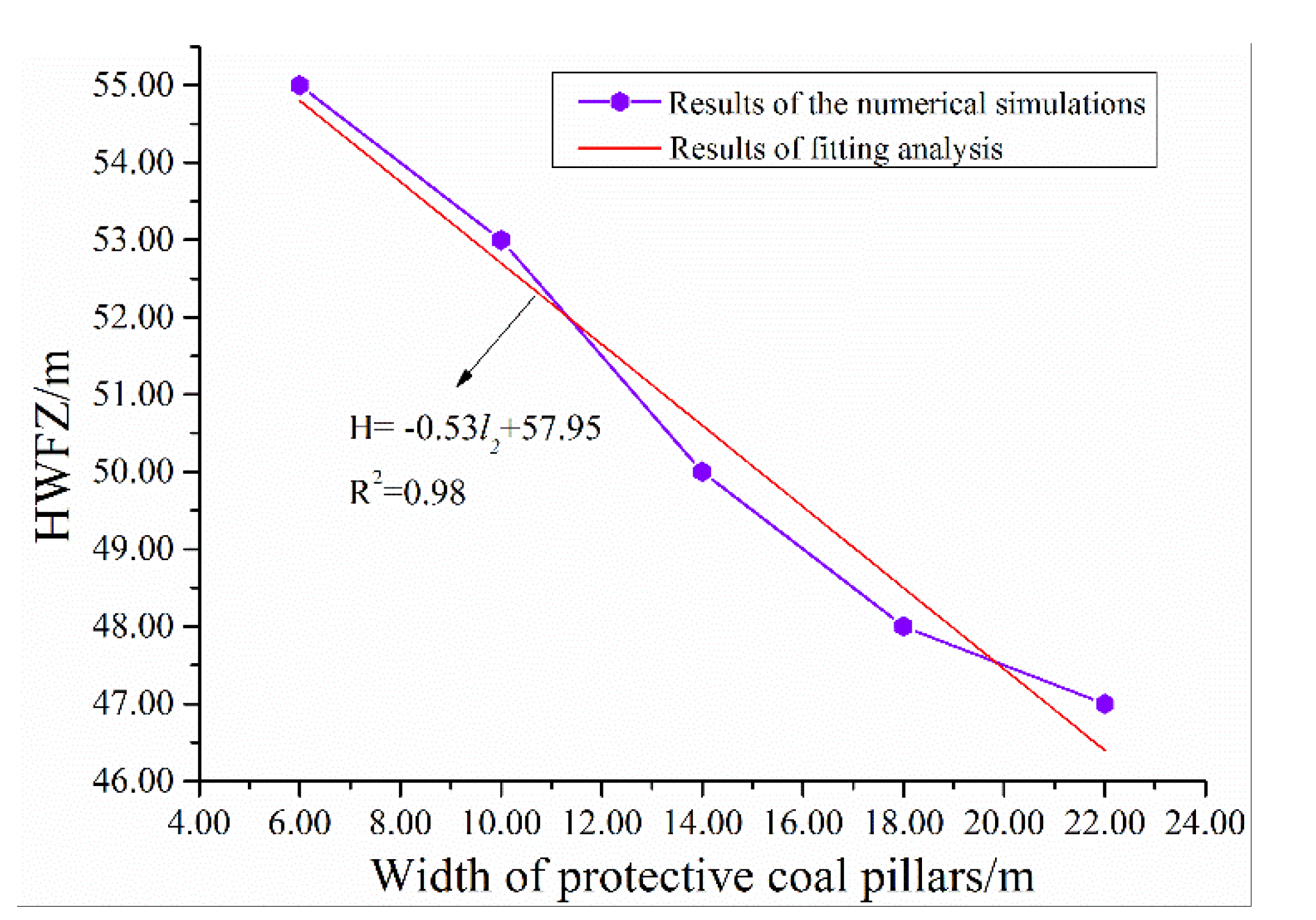
The comparison between the results of the mechanical model [40] and numerical simulation could be obtained when a stratum was completely broken or the water-conducting fractures fully penetrated the stratum in overlying strata, and the results of mechanical model and numerical simulation were very close. While a stratum was partially destroyed or the water-conducting fractures did not completely pass through the stratum, the results of the mechanical model and numerical simulation exhibit a certain difference. For example, the block length block (70.00 m) and the width of protective coal pillar (10.00 m) were constant, and when the mining height was 3.00 m, the mechanical model result was 51.00 m and the numerical simulation result was about 51.33 m, but while the mining height was 3.00 m, the result of the mechanical model was 49.00 m and the result of numerical simulation was about 49.33 m. Therefore, based on the above analysis, when a stratum was partially broken or the water-conducting fractures did not completely pass through the stratum in overlying strata, there was a certain error in the calculation results of the mechanical model.

4.3. Prediction of HWFZ Based on Multiple Nonlinear Regression

(1) Multiple nonlinear regression analysis
A multiple nonlinear regression model may be constructed based on the results of the numerical simulations:
y = α 1 x 1 + α 2 x 2 + α 3 ln x 3 + α 0
Here, let x 1 = x 1 , x 2 = x 2 , and x 3 = ln x 3 ; the nonlinear regression model in Equation (10) may then be converted into a linear regression model as follows:
y = α 1 x 1 + α 2 x 2 + α 3 x 3 + α 0
The least squares method is then used to obtain the regression coefficients, α0, α1, α2, and α3, as illustrated below:
f ( x i ) = ( y i y ^ i ) 2 = ( y i α 0 α 1 x 1 i α 2 x 2 i α 3 x 3 i ) 2 = min
In Equation (12), x 1 i , x 2 i , and x 3 i are independent variables, while yi is a dependent variable. As both the sets of variables are known observables, one may then solve the regression coefficients α0, α1, α2, and α3 by setting their first derivatives as 0. This yields the following:
{ K 11 α 1 + K 12 α 2 + K 13 α 3 = K 1 y K 21 α 1 + K 22 α 2 + K 23 α 3 = K 2 y K 31 α 1 + K 32 α 2 + K 33 α 3 = K 3 y
Here, it is revealed in Equation (13) that K i j = K j i = ( x i j x ¯ i ) ( x i j x ¯ j ) and K i y = ( x i j x ¯ i ) ( y i y ¯ i ) .
As Ki1, Ki2, Ki3, and Kiy (i = 1, 2, 3) are already known, x i j , y i , x ¯ j , x ¯ i and y ¯ i (i = 1, 2, 3) are also known. Hence, there are three equations for the three unknown regression coefficients, α0, α1, α2, and α3. These three unknowns may then be solved via either elementary matrix operations or the calculation of determinants; α0 may be solved using the values of α0, α1, α2, and α3. The accuracy of the obtained regression equation may be determined using a correlation coefficient R ( R 2 ( y , 1 , 2 , 3 , 4 ) = ( y ^ i y ¯ ) 2 ( y i y ¯ ) 2 ) . The more closely the value of R approaches 1, the more reliable the fit of the regression equation.
(2) Construction of the model for predicting HWFZ
Based on the simulation results in Section 4.2. and the aforementioned procedure, SPSS 19.0 was used to perform nonlinear regression analyses on the relationships between HWFZ and mining height, the block length, and the width of the protective coal pillars (in Figure 12, Figure 13 and Figure 14, respectively). The model equation for predicting HWFZ is:
H = 35.03 ln l 1 0.51 l 2 + 3.48 h c 105.04
The correlation coefficient of the regression model’s fit is illustrated in Table 2.
Table 2 reveals that the fit coefficient of the regression model is R2 = 0.93, which indicates an excellent level of fit and demonstrates that the equation is statistically significant. The construction of this predictive regression model enables accurate predictions for this type of geological work under varying sets of mining parameters and conditions (mining height, protective coal pillar width, and block length), thus providing a form of on-site guidance that can, to an extent, inform the design of working face layouts and key mining parameters. In addition, the application of this system for predicting HWFZ in SBM is likely to have profound significance in the prediction of HWFZ during the recovery of coal pillars in varied geological environments, and it will be of practical value for the protection of ecological environments, ensuring adequate resource utilization, and China’s sustainable development strategies.

5. Practical Applications

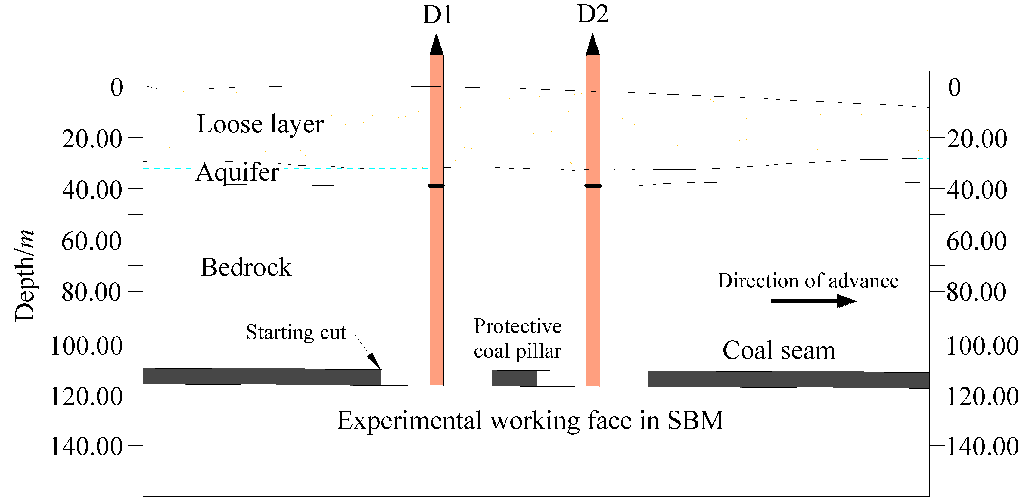
5.1. Methods for Monitoring HWFZ

During SBM recovery, HWFZ were measured through losses in drilling fluid, integrity of drilled cores, and the tomography of drilling television system in bored holes. After the working face was mined-out, two observation boreholes (D1 and D2) were installed above the working face to measure HWFZ. The layout of the boreholes was as illustrated in Figure 3 and Figure 15; boreholes D1 and D2 lie in two central positions above the working face at 35.00 m and 115.00 m, respectively, from the starting cut. The depth of these boreholes was 114.00 m, with the final drilled stratum being the floor stratum of the coal seam; the loss of washing fluid was monitored during the borehole drilling process.

5.2. Analysis of the Monitoring Data

The observed variations in washing fluid losses during the drilling of D1 and D2 are presented in Figure 16, and images of the drilling television system are shown in Figure 17 and Figure 18. When the bore depth of D1 reached 62.42 m, the loss in washing fluid increased from 0.27 to 1.93 m3/h. While there was an increase in the loss of washing fluid, the magnitude of this increase was relatively marginal, and the development of layered cracks in the drilled cores was relatively intact. Figure 17a shows an image from the drilling television system at the bore depth of 58.02 m, with morphological characteristics of rock strata being relatively complete. As the drilling depth increased, the loss of washing fluid increased to 4.03 m3/h, which was a relatively large increase in loss. The recovery rate of the drilled cores was less than 50%, and the cracks in the cores were more developed and exhibited multiple cracks with narrow widths. An image of the top boundary of HWFZ is shown in Figure 17b. The first vertical fracture appeared at 62.42 m in borehole D1. The loss of washing fluid fluctuated within a marginal range as the drilling depth continued to increase, and the cores were more shattered. Figure 17c shows that the density of the vertical fractures increased with bore depth. Hence, it is demonstrated that D1 measured an HWFZ of 47.98 m.
When the drilling depth of D2 reached 60.34 m, the loss in washing fluid increased from 0.14 to 2.27 m3/h, and the recovery rate of the drilled cores was approximately 78%. The rock cores displayed developments of layered cracks with narrow widths and did not present any distinct cracks. The image at the bore depth of 56.02 m is shown in Figure 18a, the rock strata did not have any fractures, and the morphological characteristics were complete. As the drilling depth continued to increase, the loss in washing fluid increased to 4.58 m3/h, and the fluctuations in these losses were relatively large from observations of the recovered cores, it was determined that the cores were shattered, as shown in Figure 18b, and there was an obvious vertical fracture at a bore depth of 60.34 m for the first time. The fluctuations in washing fluid loss became smaller as the drilling depth continued to increase, and the broken range of the cores was obviously increased. As can be seen in Figure 18c, the density of the vertical fractures and the broken range of rock strata increased with bore depth. Hence, it was determined that the peak of the water-conducting fracture zone was at a depth of approximately 60.34 m, which corresponds to a height of 50.06 m of the water-conducting fracture zone affected by mining.

5.3. Comparison between the Analyses of HWFZ

As shown in Table 3, the field-measured data indicates that HWFZ in the SBM working face is approximately 49 m and that it has not reached the aquifer. These results thus indicate that the HMP standard’s prediction is incompatible with the measured results, while the results of the mechanical model proposed in this study (50.30 m) and the regression prediction model (52.58 m) reasonably fit field measurements. This observation verifies that the regression prediction model is highly viable and valuable as a source of guidance, and also establishes the accuracy of the mechanical model.

6. Conclusions

(1) This study proposes the SBM process for recovering irregular blocks of coal and coal pillars. Based on the characteristics of overlying strata displacements of SBM, the key factors that affect the development of the water-conducting fracture zone and the theory of beams on elastic foundations, a mechanical model for calculating HWFZ in SBM was constructed, and an HWFZ of 50.30 m in the working face of the experimental area was calculated; this result varied substantially from the prediction of the HMP standard (75.50 m). This reveals that the empirical equation in the HMP standard is not suitable for predicting HWFZ in SBM.
(2) UDEC was used to perform simulation analyses on the various factors that determine HWFZ, and the simulations indicated that HWFZ increased linearly with an increase in mining height, increased logarithmically with an increase in the block length of the coal seam, and decreased linearly with an increase in the width of the protective coal pillars.
(3) SPSS was used to perform nonlinear regression analyses to obtain an equation for predicting HWFZ in SBM, i.e., H = 35.03 ln l1 − 0.51 l2 + 3.48 hc − 105.04. On-site measurements indicated that the mined-out working face in the experimental area had an HWFZ of approximately 49 m, which is comparable to the prediction of the regression model (52.58 m) and the calculated result of the mechanical model (50.30 m). This result verifies the reliability of the regression model proposed in this study and also establishes the accuracy of the mechanical model. The construction of this prediction system will allow for accurate predictions of HWFZ in overlying strata of SBM, which has significant implications for the rational utilization of mining resources and the protection of water resources and ecological environments.

Author Contributions

Y.Z., S.C., and L.L. conducted a thorough literature search. Y.Z. drafted the manuscript. R.G. and S.G. reviewed the final paper and made important suggestions and recommendations for paper revision.

Acknowledgments

This work was financially sponsored by the Fundamental Research Funds for the Central Universities (2018BSCXC30), and Postgraduate Research & Practice Innovation Program of Jiangsu Province (the project is under the charge of Y.Z.).

Conflicts of Interest

The authors declare no conflict of interest.

References

  1. Fan, G.W. Mechanism and Engineering Practice on Mutual Response between Underground Mining of Shallow Coal Seam and Protection of Fragile Ecological Environment. Ph.D. Thesis, China University of Mining & Technology, Xuzhou, China, 2014. [Google Scholar]
  2. Ju, J.F.; Xu, J.L. Surface stepped subsidence related to top-coal caving longwall mining of extremely thick coal seam under shallow cover. Int. J. Rock Mech. Min. Sci. 2015, 78, 27–35. [Google Scholar] [CrossRef]
  3. Cui, M.X. Annual Report on China Energy Development, 1st ed.; Social Sciences Academic Press: Beijing, China, 2008. [Google Scholar]
  4. Xing, P.W.; Song, X.M.; Fu, Y.P. Study on similar simulation of the roof strata movement laws of the large mining height workface in shallow coal seam. In Proceedings of the 2nd International Conference on Structures and Building Materials, Hangzhou, China, 10 March 2012. [Google Scholar]
  5. Zhang, D.S.; Fan, G.W.; Liu, Y.D.; Ma, L.Q. Field trials of aquifer protection in longwall mining of shallow coal seams in China. Int. J. Rock Mech. Min. Sci. 2010, 47, 908–914. [Google Scholar] [CrossRef]
  6. Zhang, D.S.; Fan, G.W.; Ma, L.Q.; Wang, X.F. Aquifer protection during longwall mining of shallow coal seams: A case study in the Shendong coalfield of China. Int. J. Coal Geol. 2011, 86, 190–196. [Google Scholar] [CrossRef]
  7. Miao, X.X.; Chen, R.H.; Bai, H.B. Fundamental concepts and mechanical analysis of water-resisting key strata in water-preserved mining. J. China Coal Soc. 2007, 32, 562–564. [Google Scholar]
  8. Miao, X.X.; Wang, A.; Sun, Y.J.; Wang, L.G.; Pu, H. Research on basic theory of mining with water resources protection and its application to arid and semi-arid mining areas. Chin. J. Rock Mech. Eng. 2009, 28, 217–227. [Google Scholar]
  9. Fan, L.M.; Zhang, X.T.; Xiang, M.X.; Zhang, H.Q.; Shen, T.; Lin, P.X. Characteristics of ground fissure development in high intensity mining area of shallow seam in Yushenfu coal field. J. China Coal Soc. 2015, 40, 1442–1447. [Google Scholar]
  10. Fan, L.M.; Ma, X.D.; Ji, R.J. Progress in engineering practice of water-preserved coal mining in western eco-environment frangible area. J. China Coal Soc. 2015, 40, 1711–1717. [Google Scholar]
  11. Liu, H.Z. Study on the Distribution Characteristics and the Exploration and Development Prospect of Coal Resource of China. Ph.D. Thesis, China University of Geosciences, Beijing, China, 2013. [Google Scholar]
  12. Ye, G.X.; Jiang, F.X.; Liu, P.L.; Feng, Z.Q.; Wang, D.Z. Design and optimization of efficient mining technology in boundary coal recovery. J. Univ. Sci. Technol. B 2007, 29, 655–659. [Google Scholar]
  13. Zhang, N.H. Study on the Theory and Practice about Mechanized Mining Technology of Bound Coal at Irregular Block Section. Master’s Thesis, China University of Mining & Technology, Xuzhou, China, 2011. [Google Scholar]
  14. Zhou, M.P. Research on Continuous Mining Methods and Rock Control Technology. Ph.D. Thesis, China University of Mining & Technology, Xuzhou, China, 2014. [Google Scholar]
  15. Cao, S.G.; Cao, Y.; Jiang, H.J. Research on catastrophe instability mechanism of section coal pillars in block mining. J. Min. Saf. Eng. 2014, 31, 908–913. [Google Scholar]
  16. Zhou, M.P.; Cao, S.G.; Jiang, X.J. The law of rock pressure in the stope with blocking mining by the continuous miner. J. Min. Saf. Eng. 2014, 31, 413–417. [Google Scholar]
  17. Booth, C.J. Strata-movement concepts and the hydrogeological impact of underground coal mining. Groundwater 1986, 24, 507–515. [Google Scholar] [CrossRef]
  18. Palchik, V. Influence of physical characteristics of weak rock mass on height of caved zone over abandoned subsurface coal mines. Environ. Geol. 2002, 42, 92–101. [Google Scholar] [CrossRef]
  19. Zhang, J.C.; Shen, B.H. Coal mining under aquifers in China: A case study. Int. J. Rock Mech. Min. Sci. 2004, 41, 629–639. [Google Scholar] [CrossRef]
  20. Zhang, W.; Zhang, D.S.; Wu, L.X.; Wang, H.Z. On-site radon detection of mining-induced fractures from overlying strata to the surface: A case study of the Baoshan coal mine in China. Energies 2014, 7, 8483–8507. [Google Scholar] [CrossRef]
  21. Elsworth, D.; Liu, J.S. The influence of mining induced subsidence on groundwater resources. Int. J. Rock Mech. Min. Sci. 1995, 8, 141–148. [Google Scholar]
  22. Adams, R.; Younger, P.L. A strategy for modeling ground water rebound in abandoned deep mine systems. Groundwater 2001, 39, 249–261. [Google Scholar] [CrossRef]
  23. Light, D.D.M.; Donovan, J.J. Mine-water flow between contiguous flooded underground coal mines with hydraulically compromised barriers. Environ. Eng. Geosci. 2015, 21, 147–164. [Google Scholar] [CrossRef]
  24. National Coal administration of China. Hydrogeological Procedures for Mines, 1st ed.; China Coal Industry Publishing House: Beijing, China, 1984. [Google Scholar]
  25. Li, X.Q.; Ren, S.Z. Classification of hydro-geological conditions in Chinese coal mines. J. China Coal Soc. 1992, 17, 89–96. [Google Scholar]
  26. Huang, Q.X. Ground pressure behavior and definition of shallow coal seams. Chin. J. Rock Mech. Eng. 2009, 28, 217–227. [Google Scholar]
  27. Peng, S.S. Longwall Mining, 1st ed.; Science Press: Morgantown, WV, USA, 2006. [Google Scholar]
  28. Palchik, V. Formation of fractured zones in overburden due to longwall mining. Environ. Geol. 2003, 44, 28–38. [Google Scholar]
  29. Qian, M.G.; Miao, X.X.; Xu, J.L. Key Strata Theory of Strata Control, 1st ed.; China University of Mining & Technology Press: Xuzhou, China, 2003. [Google Scholar]
  30. Chen, L.; Feng, X.; Xie, W.; Zeng, W.; Zheng, Z. Using a fluid–solid coupled numerical simulation to determine a suitable size for barrier pillars when mining shallow coal seams beneath an unconsolidated, confined aquifer. Mine Water Environ. 2016, 36, 1–11. [Google Scholar] [CrossRef]
  31. Hoek, E.; Brown, E.T. Underground Excavations in Rocks, 1st ed.; Institution of Mining and Metallurgy: London, UK, 1980; pp. 382–395. [Google Scholar]
  32. Chen, J.; Du, J.P.; Zhang, W.S.; Zhang, J.X. An elastic base beam model of overlying strata movement during coal mining with gangue back-filling. J. China Univ. Min. Technol. 2012, 41, 14–19. [Google Scholar]
  33. He, F.L.; Wang, X.M.; Xie, R.S. study on elastic foundation beam model of cracked coal seam roadway roof with ultra large section. Coal Sci. Technol. 2014, 42, 34–36. [Google Scholar]
  34. Selvadurai, A.P.S. Elastic Analysis of Soil-Foundation Interaction, 1st ed.; Elsevier Scientific Publish: Amsterdam, The Netherlands, 1979. [Google Scholar]
  35. Long, Y.Q. Computation of Elastically Supported Beams, 1st ed.; People’s Education Press: Beijing, China, 1981. [Google Scholar]
  36. Yang, X.X. The feature of foundation pressure on winkler foundation beam with one fixed end and its application. Eng. Mech. 2006, 23, 76–79. [Google Scholar]
  37. Deng, X.J.; Zhang, J.X.; Huang, P.; Zhang, Q.; Hao, X.F. Roof movement characteristics in extra thick coal seam mining with the upward slicing filling technology. China Coal Soc. 2015, 40, 994–1000. [Google Scholar]
  38. Wang, F.T.; Tu, S.H.; Zhang, C.; Zhang, Y.W.; Bai, Q.S. Evolution mechanism of water-flowing zones and control technology for longwall mining in shallow coal seams beneath gully topography. Environ. Earth Sci. 2016, 75, 1309. [Google Scholar] [CrossRef]
  39. Du, F.; Gao, R. Development patterns of fractured water-conducting zones in longwall mining of thick coal seams—A case study on safe mining under the Zhuozhang river. Energies 2017, 10, 1856. [Google Scholar] [CrossRef]
  40. Zhang, Y.; Cao, S.G.; Lan, L.X.; Gao, R.; Yan, H. Analysis of Development Pattern of a Water-Flowing Fissure Zone in Shortwall Block Mining. Energies 2017, 10, 734. [Google Scholar] [CrossRef]
Figure 1. Distribution of coal resources in the mining areas of western China and the ecological issues caused by mining operations.
Sustainability 10 01636 g001
Figure 2. Columnar pattern of the coal-bearing rocks and their physical and mechanical properties.
Sustainability 10 01636 g002
Figure 3. Location and layout of the working face of the experimental area of shortwall block mining (SBM). (a) Location of experimental area of SBM; (b) Layout of the working face for SBM.
Sustainability 10 01636 g003
Figure 4. Technical system of SBM and the layout of the working face.
Sustainability 10 01636 g004
Figure 5. Coal pillar recovery process and the main equipment involved.
Sustainability 10 01636 g005
Figure 6. Characteristics of the overlying strata in longwall mining and SBM. (a) Characteristics of overlying strata displacements caused by conventional longwall caving methods; (b) Characteristics of overlying strata displacements caused by SBM.
Sustainability 10 01636 g006aSustainability 10 01636 g006b
Figure 7. Schematic of factors that determine HWFZ.
Sustainability 10 01636 g007
Figure 8. Schematic of the basic environmental stresses in SBM.
Sustainability 10 01636 g008
Figure 9. Mechanical model for an arbitrary stratum in SBM.
Sustainability 10 01636 g009
Figure 10. Design procedure for the predictive system for HWFZ in SBM.
Sustainability 10 01636 g010
Figure 11. Mechanical model for numerical calculations.
Sustainability 10 01636 g011
Figure 12. Relationship between HWFZ and mining heights.
Sustainability 10 01636 g012
Figure 13. Relationship between HWFZ and the width of protective coal pillars.
Sustainability 10 01636 g013
Figure 14. Relationship between HWFZ and the length of block.
Sustainability 10 01636 g014
Figure 15. Position and layout of the aquifer and boreholes.
Sustainability 10 01636 g015
Figure 16. Relationship between borehole depth and loss of washing fluid.
Sustainability 10 01636 g016
Figure 17. Image of drilling television system in borehole D1. (a) No fracture; (b) First vertical fracture; (c) Fractured zone.
Sustainability 10 01636 g017
Figure 18. Image of drilling television system in borehole D2. (a) No fracture; (b) First vertical fracture; (c) Fractured zone.
Sustainability 10 01636 g018
Table 1. Numerical simulation cases.
CaseMining Height/mBlock Length/mWidth of Protective Coal Pillar/m
12.00/2.40/2.80/3.20/3.60/4.0070.0010.00
24.0070.006.00/10.00/12.00/14.00/18.00/22.00
34.0050.00/55.00/60.00/70.00/75.00/80.0010.00
Table 2. Correlation coefficient of the regression model’s fit.
RR2
0.970.93
Table 3. Comparison between the analyses of HWFZ.
HWFZMeasured ResultResult Predicted by the HMP StandardCalculation of Mechanical AnalysisPrediction by this Study
D1D2
47.98 m50.06 m75.00 m50.30 m52.58 m

