Mechanism for Controlling Floor Heave of Mining Roadways Using Reinforcing Roof and Sidewalls in Underground Coal Mine


1
Key Laboratory of Deep Coal Resource Mining, Ministry of Education of China, School of Mines, China University of Mining and Technology, Xuzhou 221116, China
2
Coal Mining and Designing Branch, China Coal Research Institute, Beijing 100013, China
3
School of Public Policy and Urban Affairs, College of Social Sciences and Humanities, Northeastern University, Boston, MA 02115, USA
*
Authors to whom correspondence should be addressed.
Sustainability 2018, 10(5), 1413; https://doi.org/10.3390/su10051413
Submission received: 19 March 2018
/
Revised: 15 April 2018
/
Accepted: 26 April 2018
/
Published: 3 May 2018
(This article belongs to the Section Energy Sustainability)
Abstract
:Controlling floor heave plays an important role in the stability of mining roadways that is pivotal to the sustainable, safe, and efficient development of coal resources in underground coal mines. In order to propose highly efficient and economical methods of controlling floor heave, numerical simulation, laboratory physical simulation, and engineering practice were carried out to reveal the mechanism of reinforcing roof and sidewalls to control the floor heave of the mining roadway, return airway 15208, in the Xinjing Coal Mine in the Yanquan mining area of China. The numerical simulation demonstrated that the surrounding rock of the roadway underwent expansion and deformation, accompanied by redistribution of the surrounding rock stress due to the reinforcement of the roof and two sidewalls. The laboratory physical simulation revealed that the reinforcing roof and sidewalls decreased the bed separation of the floor and reduced the quantity of the displacement of the floor in Coal Seam 15. Engineering practice showed that the floor heave in the roadway, the roof, and the sidewalls, which was reinforced by intensive bolts combined with steel belt, wire mesh, and cable, was significantly reduced compared with that with lower supporting intensity of roof and sidewalls. The floor heave could be successfully controlled.
1. Introduction
According to incomplete statistics, the length of mining roadways exceeds 8000 km, which accounts for 80% of the total length of newly drifting roadway in China, in recent years. At present, bolts are widely applied for roadway support because of their low cost, active reinforcement, and efficient installation for rapid excavation, which are essential to keeping the balance of excavation speed and production in underground coal mines. However, floor heave is usually a serious failure phenomenon in mining roadways [1,2,3,4,5,6]. Specially, it is much more severe in the front of the coal working face due to the mining abutment pressure. The large deformations, e.g., the serious heave, have far-reaching negative effects on the surrounding rock stability of the mining roadway. Engineering practices [7,8,9] have observed frequent and dramatic floor heave in the mining roadway during extracting coal seams with loose and fractured roof. Controlling floor heave plays a crucial role in the stability of mining roadways that is pivotal to transportation, ventilation, and other essential services for sustainable, safe, and highly efficient development of coal resources in underground coal mines [10,11,12].
In order to solve the problem of serious floor heave in mining roadway, the inverted arch support and stress relief slot has been developed to deal with the fractured floor and stress concentrations, respectively [13,14,15,16,17]. Inverted arch support for the enhancing floor was achieved by using bolts, cables, U-shaped steel, and grouting [13]. The stress relief slot was accomplished by cutting a slot in floor of roadway to reduce concentration stress [16]. Floor beam layout using grooving, full-length grouting, and suitable reinforced support countermeasures for the key zone (for instance, two corners on the floor) are proposed to reduce the deformation of the floor heave [18,19,20]. Through such methods, the severe floor heave can be effectively reduced.
However, these methods are difficult to carry out. Moreover, the cost is relatively expensive. Therefore, it is urgently necessary to investigate other effective techniques to bring severe floor heave under control. The surrounding rock of roadways is constituted of roof, sidewalls, floor, and the rock mass around them. The stress state and deformation failure characteristics of various parts of the surrounding rock are significantly different.
The stability of rock mass in the roof is one of the most important factors that decides stress distribution and plastic zone scope of surrounding rock, thus affecting floor stability. Hence, some scholars have studied reinforcing roof and sidewalls for controlling floor heave. For instance, Wang et al. studied the technology of reinforcing roof to reduce floor heave in mining roadway [21]. Yu and Gu studied a novel technology for supporting surrounding rock against deformations. The results showed that the reinforced sidewalls caused significant decreases of floor heave [22]. Sun et al. and Zhong et al. put forward the technology of reinforcing surrounding rock to realize the floor stability in inclined strata and soft rock [23,24]. However, aiming at the stability of floor and control of floor heave, many scholars also focused on the water effect [25].
From the above, it is understood that roof strength has an impact on floor heave but that the mechanism of reinforcing roof and sidewalls to the control floor heave of the mining roadway is not clear yet. Consequently, further investigation is required to understand the failure patterns of the surrounding rock and the stress state of the rock bolt support reinforcing the roof and sidewalls.
This study was conducted in return airway 15208 in the first district of the Xinjing Coal Mine in the Yanquan mining area in Shanxi, China. The return airway lies in Coal Seam 15. Numerical and physical simulations were conducted to analyze the stress state and the laws of fractures development of surrounding rock resulting from reinforcing the roof and sidewalls. Subsequently, the simulation results were confirmed through field trial.
2. Geological Profiles
Coal Seam 15 was extracted using the long-wall mining, which was one of main workable coal seams in the Yangquan mining area. The strike length and the dip width of working face 15208 in Coal Seam 15 in the Xinjing Coal Mine were 1458 m and 217 m, respectively, as shown in Figure 1. The buried depth of the return airway in working face 15208 was 490 m. The cross-section of the roadway was 4.5 m wide and 3.0 m high. The roof strata of Coal Seam 15 were mainly composed mudstone and limestone, whilst the floor lithology mainly consisted of mudstone and fine sandstone as shown in Table 1.
The support scheme used bolting with wire mesh in return airway 15208. Five cables per row in the roof, of which diameter, length, and inter-row spacing were 21.6 mm, 8300 mm, and 1025 mm × 800 mm, respectively. In the roof, pre-tightening force of each cable was not lower than 250 kN, and each row of cables cooperated with a corrugated steel strip (Length × Width × Thickness: 4400 mm × 280 mm × 4 mm). There were three cables per line in each sidewall. Additionally, the diameter, length, and inter-row spacing of cables were 21.6 mm, 4500 mm, and 1025 mm × 800 mm, respectively. In both sidewalls, pre-tightening force of each cable was not lower than 120 kN.
3. Numerical Simulations
3.1. Numerical Model
The numerical simulation by means of FLAC3D from Itasca of USA [26] was performed to analyze the characteristics of the stress distribution of surrounding rock before and after reinforcing the roof and sidewalls, which set a foundation for the mechanism. Two models were designed and established on the geological conditions of the return airway in working face 15208 (the length, width, and height were 40 m, 5 m, and 30 m, respectively). The whole model was divided into 48,000 units. A standard hexahedral format was used with free boundaries for the upper part or upper side [27], as shown in Figure 2.
The simulation calculation was executed according to the Mohr-Coulomb’s yield criterion. The main mechanical parameters obtained from field practice and laboratory experiments were illustrated in Table 1. Horizontal displacements were fixed at the lateral boundaries. Horizontal and vertical displacements were fixed at the bottom boundary. The top boundary was set free. A vertical stress of 11.09 MPa and a horizontal stress of 13.22 MPa were applied at the top and lateral boundaries. The stress values of surrounding rock were acquired from field measurement.
Two schemes were used to analyze stability of the floor in the condition of with or without reinforcing roof and sidewalls, respectively, as shown in Table 2.
The units of cable and shell were adopted for simulating bolts and steel belts, respectively. The equilibration of each step was evaluated using the maximal unbalanced force. To analyze the effect of controlling floor heave through reinforcing roof and sidewalls, both stress and plastic zones were extracted in the calculation process [28].
3.2. Results and Discussion
3.2.1. Horizontal Stress
According to above calculation, the stress distribution of the surrounding rock was obtained before and after reinforcing the roof and sidewalls, distance from surface to the depth of roadway surrounding rock as shown in Figure 3.
According to Figure 3, the increasing of stresses in the shallow reinforced surrounding rock indicated that the residual strength of reinforced area was obviously improved. The horizontal stress in the reinforced area quickly increased from the roadway surface to 1-m-deep surrounding rock, whereas the horizontal stress of reinforced area in 1–2-m-deep surrounding rock gradually increased. The horizontal stress in the roof, left sidewall, and right sidewall were found to be approximately 8 MPa, 5 MPa, and 5 MPa, respectively. The stress increased gradually to a new peak with further calculating. The high stress was transferred to far field areas from the surface of surrounding rock, because the roof and two sidewalls were reinforced.
The stress in the shallow region in the floor in Scheme 2 gradually increased but remained higher than the stress of Scheme 1, which could demonstrate that the residual strength of floor was improved simultaneously.
3.2.2. Vertical Stress
The vertical stress distribution of the surrounding rock was obtained from simulation calculation results, as shown in Figure 4.
Figure 4 shows that the vertical stress of roof and floor is in agreement with the horizontal-stress. However, the figure also showed that there was obvious otherness in stress distribution characteristics of vertical and horizontal stresses of two sidewalls.
With the reinforcement of two sidewalls, its carrying capacity was improved, and the deformations of surrounding rock were reduced. Therefore, the vertical stress of Scheme 2 was apparently higher than Scheme 1 within 2.5 m of two sidewalls.
However, the vertical stress between 0-m-deep and 2.5-m-deep surrounding rock of sidewalls in Scheme 2 was reduced compared with Scheme 1. There were two reasons to illustrate the situation. Firstly, high vertical stress decreased due to deformation of surrounding rock. Secondly, high vertical stress main concentrated within 2.5 m-deep anchorage rock mass. The decrease of vertical stress in two sidewalls contributed to the floor protection.
3.2.3. Plastic Zones
As shown in Figure 5, the form and scope of the plastic zone distribution of Scheme 1 was significantly different from Scheme 2. Plastic zone form of the former was approximate to oval, whilst the latter was a cross. The boundary maximum value of Scheme 1 was 2.5 m bigger than Scheme 1. The most obvious effect of reinforcing roof and sidewalls was that plastic zone was eliminated in all four corners of the roadway.
4. Physical Simulations
4.1. Physical Models
Two simulations were performed, corresponding to whether the roof and sidewalls were reinforced. The surface deformation of surrounding rock and the stress state of the bolting were subsequently recorded by canon digital camera, minute displacement sensor, and micro bolt dynamometers, respectively. A physical model with a geometrical scale of 25:1 was used for the test, which was designed with the dimensions of the two dimensionally similar models, which were 1.0 m × 1.0 m × 0.3 m (length × width × height). The zinc-lead alloy wire, aluminum sheet, and glue 405 were employed for the simulation of bolting, steel belt, and anchorage agent, respectively. The different rock properties were simulated with the various proportions of sand, calcium carbonate, and gypsum. In addition, mica powder was used to model the bedding layers between two strata.
The average unit weight of the materials used to establish the model was 15,000 N/m3. The volume-weight similarity ratio of the model was determined to be 0.6:1. After calculations based on the above numerical value, it was found that the time similarity ratio and stress similarity ratio was 0.2:1 and 0.024:1, respectively. The measurement value in situ (in the front of working face) of maximum horizontal stress, minimum horizontal stress, and vertical stress and is 13.22 MPa, 6.90 MPa, and 11.09 MPa, respectively. The corresponding model boundaries stress of 0.32 MPa, 0.17 MPa, and 0.27 MPa were gained based on the stress similarity, which multistage applied by hydraulic cylinder.
Regarding whether to reinforce the roof and sidewalls, the experiment was divided into two schemes. The roof and sidewalls were not reinforced in Scheme 1, and the contrary was the case in Scheme 2. In Scheme 2, the roof and sidewalls were reinforced by 75 sets of bolting models, which included the component and five steel belts. Ten micro bolt dynamometers were employed to record stress variation of bolting models. A camera system was used to collect information of alteration of surrounding rocks surface. Figure 6 shows Scheme 2.
In the mining process of working face 15208, the abutment pressure had increased gradually with coal working face advancing. To simulate the field site, the boundaries stress model was applied using multi-stage loading. There were 8 h of non-working time in each 24-h period, and the distance of mining was about 5 m each day; the distance of 12 m required 2.4 days of mining. According to the similarity ratio, the boundary stresses were loaded in three sessions (12 m/5 m = 2.4) over 9.3 h (2.4 days × 16 h/5); the time interval was 1.6 min (8 h/5).
4.2. Results and Discussion
4.2.1. Fracture Characteristics of Surrounding Rock in Scheme 1
In the mining process of working face 15208, the abutment pressure increased gradually with coal face advancement. To simulate this fact, the boundaries’ stress model was applied using the multistage loading. There were 8 h of non-working time in each 24-h period, and the distance of mining was about 5 m each day; the distance of 12 m required 2.4 days of mining. According to the similarity ratio, the boundaries stress were loaded in three sessions (12 m/5 m = 2.4) over 9.3 h (2.4 × 16 h/5); the time interval was 1.6 min (8 h/5).
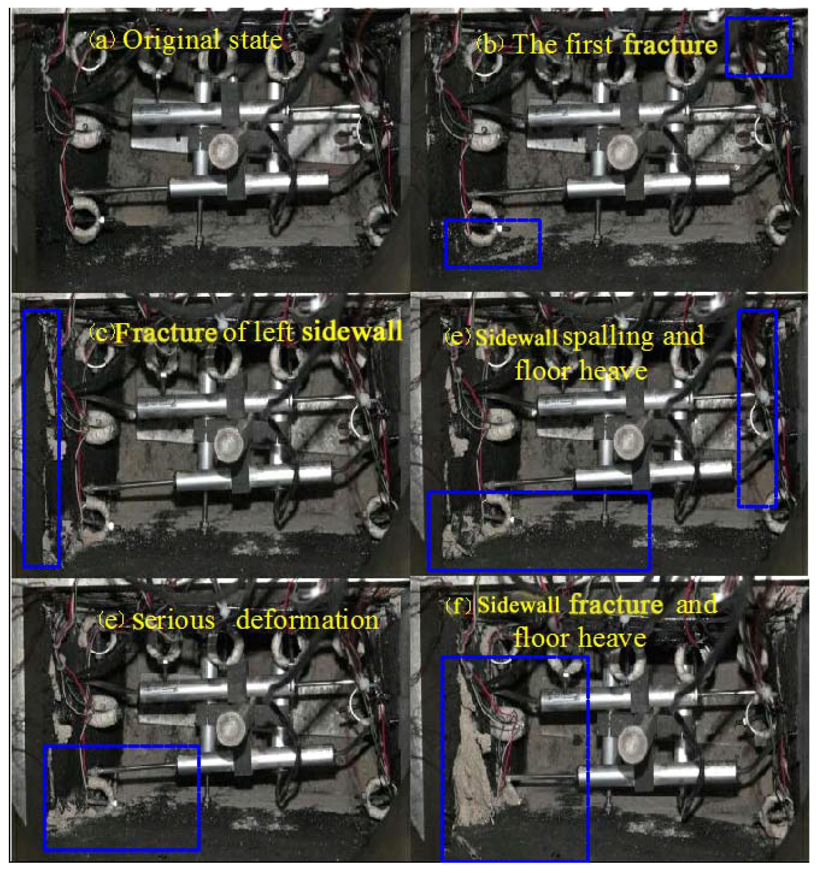
When the stress reached about one third of the design load value, fractures first appeared in the corner of floor and right sidewall. Fractures continued extending and passed through the floor along left-right direction, which is thin layer, resulting from the increase of stress in surrounding rock, as illustrated in Figure 7a–c. The loading value reached two thirds of design load value, fractures developed in both the corners of roof and two sidewalls, and the value of floor heave was about 300 mm; Figure 7d shows the position of fractures and floor heaves. Note that these fractures developed in roof, floor, and related sites only, meaning that high horizontal stress can affect the stability of roof and floor severely. A 1.7-m-long fracture was formed in the right sidewall (Figure 7e). It was quite clear that the stress progress in surrounding rock had the destructive effect of breaking the stability of surrounding rock.
An increasing number of fractures formed in surrounding rock as the stress developed. Overall, there was a very serious deformation and damages in surrounding rock; the maximum heave floor, reduction of cross section, and the roof convergence were about 1700 mm, 45%, and 400 mm, respectively. Figure 7f and Figure 8 shows the fractures characteristics of the surrounding rock.
When the stress reached about one third of design load value, the first fracture appeared in the corner of floor and right sidewall. Fractures continued extending and passed through the floor along left-right direction, which is thin layer, resulting from the increase of stresses in surrounding rock, as illustrated in Figure 7a–c. The loading value reached two thirds of design value of load, and the fractures were developed in both the corners of roof and two sidewalls; the value of floor heave was about 0.3 m; Figure 7c shows the position of fractures and floor heaves. Note that these fractures were developed in roof, floor, and related sites only, meaning that high horizontal stress can severely affect the stability of roof and floor. A 1.7 m long fracture was formed in the right sidewall in Figure 7e. It was quite clear that the stress progress in surrounding rock has the destructive effect of breaking the stability of surrounding rock.
4.2.2. Fracture Characteristics of Surrounding Rock in Scheme 2
According to the design of the Scheme 2, the roof and sidewalls of the surrounding rock were reinforced. Figure 9 shows the deformation and fractures evolution of surrounding rock during loading procedure.
When the stress reached about one third of designed load value, the fracture occurred in the corner of lower left and upper right, as shown in Figure 9b. The fracture increased further as the loading progressed. When the loading reached one second of designed load value, the fracture (3 m long) crossed the left sidewall along up-down direction first. This was far different from Scheme 1, in which the fracture developed in floor first. The Figure 9c shows the fracture state at that moment.
The fracture developed at the corner of lower left and upper right during the stress reached by two thirds of the designed value. It is obvious that floor deformation of lower left and upper right increased much both, but nonetheless, the quantity of floor heave was much smaller than Scheme 1 on an equal footing, as shown in Figure 9d.
With the stress in its final stage, minute displacement sensor of lower left was buried by deformation of surrounding rock. The phenomenon of bed separation of floor was not observed in the visual field at that same time. Figure 9e shows the final status of roadway section. Figure 10 shows the fracture final status of surrounding rock.
By contrasting Figure 8 and Figure 10, it is clear that the displacement and bed separation of floor was significantly reduced. Bedding separation of roof was not observed at that same time. Two distinct outlines of fracture occurred in two sidewalls. The maximum floor heave, reduction of cross section, and the roof convergence was about 0.45 m, 25%, and 0.4 cm, respectively.
In the same way, with the help of analyzing the video data, the process of surrounding rock failure of Scheme 2 in following steps: lower left corner → upper right corner → roof → upper right corner → lower left corner → upper right corner → upper left corner → roof → two sidewalls → floor → roof → two sidewalls → floor.
Therefore, it can be concluded that the reinforce of roof and sidewalls affected the process of stress distribution, forcing the high stress to shift from floor to roof and two sidewalls, which could influence the failure process of surrounding rock. The floor heave was efficiently controlled with the reduction of displacements and bed separation, which constitutes an external phenomenon.
4.2.3. Displacements and Axial Load of Bolts
According to the time similarity ratio and stress similarity ratio, the curve of displacement and bolting axial force were developed below, to show deformation rule and bolt axial force condition in the experiment.
As shown in Figure 11a, the displacement of surrounding rock began to increase on the first day. There was a stage of increasing rapidly 1–1.5 days after first day. Moreover, the displacement velocities in the right sidewall and floor were significantly faster than the left sidewall and roof. The curve of displacement appeared in state of fluctuation in the period of stopping loading (1.6–2.0 day). A new increase in right sidewall and floor occurred on the second day while the loading continued working, with unmarked, corresponding increases in the roof and left sidewall. The displacement of floor, right sidewall, roof, and left sidewall were maintained at the approximate value of 1.6 m, 1.0 m, 0.6 m, and 0.3 m in the end, respectively.
Through displacement curve comparison in Figure 11, there was a remarkable change of curve shape before and after the reinforced of roof and two sidewalls; the displacement curve of Scheme 2 became relatively flatter, and with the increasing displacement, the fluctuation of curve became smaller after 1.8 day. The maximum displacement of floor was about 1.0 m, which decreased displacement by 38% compared to the Scheme 1. The displacement of right sidewall, roof, and left sidewall were maintained at the approximate values of 0.2 m, 0.4 m, and 0.3 m in the end, respectively.
Figure 12a showed that the change of bolt axial force of two sidewalls in the process of experiment. Firstly, the axial force increased at about 0.9 day, and subsequently, it decreased. At last, the axial force tended to stabilize. The figure also shows that the force value of lower left and lower right sidewalls was bigger than that of the center, which illustrates that the lower parts of two sidewalls were high stress concentration districts. The obvious fluctuation of axial loads indicates that the failure occurred in surrounding rock of two sidewalls, for example, the curve of left center had a fluctuation on the second day; this illustrates the force could not pass it to the sensor immediately, and the surrounding rock appeared loose or broken along bolt axis.
As shown in Figure 12b, the curve slope was obviously higher than Figure 12a, and the majority of displacements mainly focused on third day. The increasing point of the roof was prolonged 0.4 days than two sidewalls, which verified the two sidewalls were firstly in failure state. The figure also showed that the axial loads of bolts in the right and left center in the roof were greater than those of the central, left, and right parts in the roof, indicating that the force condition of roof is approximate symmetric.
5. Engineer Measurements
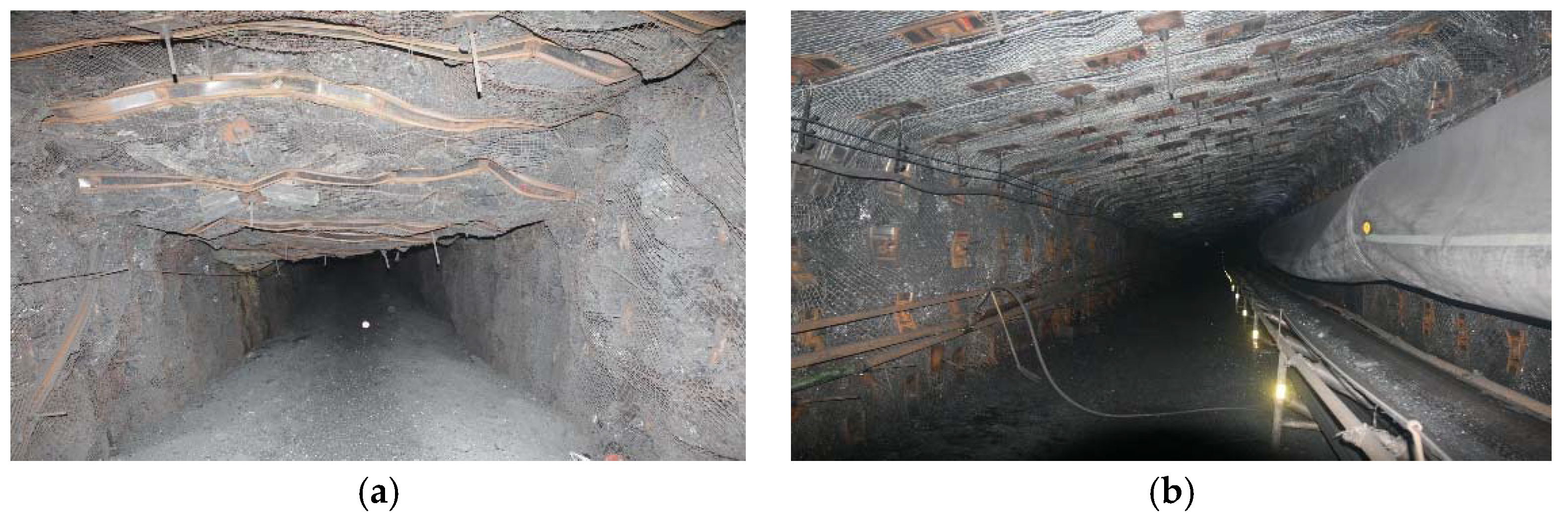
The roof and sidewalls of return airway 12580 in the Xinjing Coal Mine (a tunnel adjoining return airway 15208) were reinforced by bolt, steel strip, and wire mesh, support strength of which was higher than return airway 15208, as shown in Table 3. The deformations of the surrounding rock of return airways 12580 and 15208 were analyzed based on in-site measurement.
The deformations of surrounding rocks of the roadway were monitored using explosion-proof camera. Figure 13 shows the situations in the field sites.
According to the pictures, when the roof and sidewalls were reinforced by low support strength, the deformation of surrounding rock was serious, especially floor heave, and seriously threatened the safety in production. On the contrary, the strength of roof and sidewalls were improved by high strength structure. The rocks surrounding return airway 12580 was relatively stable; thus, both safety and high-efficiency during mining were ensured.
6. Discussion
The above research demonstrates that the reinforcement of roof and sidewalls improves the stability of floor effectively. The floor heave is controlled, and the maintenance cost of roadway is greatly reduced. On the other hand, ensuring the safety of rocks surrounding roadways would increase the recovery rate of coal resources. In conclusion, the research results are of great significance for the safe and highly efficiency development of underground resources.
7. Conclusions
Controlling floor heave plays an important role in the stability of mining roadways that is pivotal to the sustainable, safe, and efficient development of coal resources in underground coal mines. The results were based on the analysis of the numerical simulation, laboratory physical simulation, and engineering practice in return airway 15208 in the Xinji Coal Mine that provide valuable guidance for the controlling floor heave in mining roadways. Some conclusions are summarized below.
- (1)
- The numerical analysis shows that while reinforcing the roof and sidewalls, the stress in the reinforced area was higher than the unsupported area. The stress increased in a region that was located about 1 m away from the surface surrounding rock of roadway. Moreover, the pressure increased gradually to a new peak within 3–4 m. With the reinforcement of roof and sidewalls, the stress in the shallow region in the floor increased, this demonstrates that the residual strength of the floor was correspondingly improved at the same time.
- (2)
- The physical simulation revealed that reinforced roof and sidewalls improve the bed separation of the floor and reduce the quantity of displacement of the floor in Coal Seam 15. The bed separation of the roof was not observed at the same time. Therefore, it could be concluded that the reinforced roof and sidewalls affected the process of stress distribution, improving the strength of the reinforcement area and forcing the high stress to shift from the shallow to the deep, which could influence the failure process of the surrounding rock.
- (3)
- In comparison to the other parts in return airway 15208, in which supporting intensity of roof and sidewalls was higher, the floor heave was remarkably reduced. When the roof and sidewalls were reinforced with cables and intensive bolts, the floor heave of the return airway 15208 could be easily controlled. Thus, the reinforcement of the roof and sidewalls effectively controls the floor heave.
Author Contributions
All of the authors contributed extensively to the work. G.G., H.K., and D.Q. conceived and designed the numerical and physical simulations. G.G. contributed to field measurements. G.G. and D.Q. analyzed the data. G.G. wrote the paper. D.Q., F.G., and Y.W. modified the manuscript.
Acknowledgments
This work was financially supported by the National Natural Science Foundation of China (Grant No. 51704277), the Special Funding Project of Ground Control of Roadways in YangQuan Mine (Grant No. GY16036), the Open Foundation Project of Hunan Provincial Key Laboratory of Safe Mining Techniques of Coal Mines (Grant No. E21730), the Project Funded by Chinese Postdoctoral Science Foundation (Grant No. 2017M621874), the Project Funded by the Productivity Conversion Fund (Grant No. KJ-2015-TDKC-06), and the Project Funded by the Priority Academic Scheme Development of Jiangsu Higher Education Institutions.
Conflicts of Interest
The authors declare no conflict of interest.
References
- Kang, H.; Lin, J.; Yan, L. Study on characteristics of underground in-situ stress distribution in Shanxi coal mining fields. Chin. J. Geophys. 2009, 52, 1728–1792. (In Chinese) [Google Scholar]
- Kang, H.; Jian, L.; Wu, Y. Development of high pensioned and intensive supporting system and its application in coal mine roadways. J. Procedia Earth Planet. Sci. 2009, 1, 479–485. (In Chinese) [Google Scholar]
- Alehossein, H.; Poulsen, B.A. Stress analysis of long-wall top coal caving. Int. J. Rock Mech. Min. Sci. 2010, 47, 30–41. [Google Scholar] [CrossRef]
- Hebblew, B.K.; Lu, T. Geo mechanical behaviour of laminated, weak coal mine roof strata and the implications for a ground reinforcement strategy. Int. J. Rock Mech. Min. Sci. 2004, 41, 147–157. [Google Scholar] [CrossRef]
- Kang, H.; Lin, J.; Fan, M.J. Investigation on support pattern of a coal mine roadway within soft rocks—A case study. Int. J. Coal Geol. 2015, 140, 31–40. [Google Scholar] [CrossRef]
- Craig, P.; Serkan, S.; Hagan, P. Investigations into the corrosive environments contributing to premature failure of Australian coal mine rock bolts. Int. J. Rock Mech. Min. Sci. 2016, 26, 59–64. [Google Scholar] [CrossRef]
- Mohamed, K.M.; Murphy, M.M.; Lawson, H.E. Analysis of the current sidewall support practices and techniques in U.S. coal mines. Int. J. Min. Sci. Technol. 2016, 26, 77–87. [Google Scholar] [CrossRef] [PubMed]
- Yan, H.; He, F. A new cable truss support system for coal roadways affected by dynamic pressure. Int. J. Min. Sci. Technol. 2012, 22, 613–617. [Google Scholar]
- Li, C.C. A new energy-absorbing bolt for rock support in high stress rock masses. Int. J. Rock Mech. Min. Sci. 2010, 47, 396–404. [Google Scholar]
- Gao, Y.; Liu, D.; Zhang, X.; He, M. Analysis and optimization of entry stability in underground longwall mining. Sustainability 2017, 9, 2079. [Google Scholar] [CrossRef]
- Zhang, Z.; Shimada, H.; Sasaoka, T.; Hamanaka, A. Stability control of retained goaf-side gateroad under different roof conditions in deep underground y type longwall mining. Sustainability 2017, 9, 1671. [Google Scholar] [CrossRef]
- Qian, D.; Zhang, N.; Pan, D.; Xie, Z.; Shimada, H.; Wang, Y.; Zhang, C.; Zhang, N. Stability of deep underground openings through large fault zones in argillaceous rock. Sustainability 2017, 9, 2153. [Google Scholar] [CrossRef]
- Jiang, Y.D.; Zhao, Y.X.; Liu, W.G.; Li, Q. Research on floor heave of roadway in deep mining. Chin. J. Rock Mech. Eng. 2004, 14, 2396–2401. (In Chinese) [Google Scholar]
- Wang, C.; Wang, Y.; Lu, S. Deformational behaviour of roadways in soft rocks in underground coal mines and principles for stability control. Int. J. Rock Mech. Min. Sci. 2000, 37, 937–946. [Google Scholar] [CrossRef]
- Stankus, J.C.; Peng, S.S. Floor bolting for control of mine floor heave. Min. Eng. 1994, 46, 1099–1102. [Google Scholar]
- Guo, B.H.; Lu, T.K. Analysis of floor heave mechanism and cutting control technique in deep mines. J. Min. Saf. Eng. 2008, 25, 91–94. (In Chinese) [Google Scholar]
- Chang, Q.; Zhou, H.; Xie, Z.; Shen, S. Anchoring mechanism and application of hydraulic expansion bolts used in soft rock roadway floor heave control. Int. J. Min. Sci. Technol. 2013, 3, 323–328. [Google Scholar] [CrossRef]
- Cao, R.; Cao, P.; Lin, H. Support technology of deep roadway under high stress and its application. Int. J. Min. Sci. Technol. 2016, 26, 787–793. [Google Scholar] [CrossRef]
- Sun, X.; Wang, D.; Feng, J.; Zhang, C.; Chen, Y. Deformation control of asymmetric floor heave in a deep rock roadway: A case study. Int. J. Min. Sci. Technol. 2014, 24, 799–804. [Google Scholar] [CrossRef]
- Cao, R.; Cao, P.; Lin, H. A kind of control technology for squeezing failure in deep roadways: A case study. Geomat. Nat. Hazards Risk 2017, 1, 1–15. [Google Scholar] [CrossRef]
- Wang, W.; Hou, C.; Li, X. A study on mechanical principle of floor heave of roadway driving along next goaf in coal face with fully mechanized top-coal caving. Rock Mech. Nat. Int. 2001, 1, 351–354. [Google Scholar]
- Yu, Y.; Gu, S.; Li, J. Study on the mechanism and control technology of floor heave in the laneway. Power Energy Eng. Conf. 2010, 11, 617–620. [Google Scholar]
- Sun, X.; Chen, F.; He, M. Physical modeling of floor heave for the deep-buried roadway excavated in ten degree inclined strata using infrared thermal imaging technology. Tunn. Undergr. Space Technol. 2017, 63, 228–243. [Google Scholar] [CrossRef]
- Zhong, Z.; Tu, Y.; Liu, X. Occurrence mechanism and control technology of the floor heave disaster for soft-rock tunnel. Disaster Adv. 2012, 5, 987–992. [Google Scholar]
- Tang, S.B.; Tang, C.A. Numerical studies on tunnel floor heave in swelling ground under humid conditions. Int. J. Rock Mech. Min. Sci. 2012, 55, 139–150. [Google Scholar] [CrossRef]
- Fast Lagrangian Analysis of Continua in 3 Dimension, version 6.0; Itasca: Minneapolis, MN, USA, 2016.
- Lu, Y.; Cheng, Y.; Ge, Z.; Cheng, L.; Zuo, S.; Zhong, J. Determination of fracture initiation locations during cross-measure drilling for hydraulic fracturing of coal seams. Energies 2016, 9, 358. [Google Scholar] [CrossRef]
- Ma, D.; Bai, H.; Wang, Y. Mechanical behavior of a coal seam penetrated by a karst collapse pillar: Mining-induced groundwater inrush risk. Nat. Hazards 2015, 75, 2137–2151. [Google Scholar] [CrossRef]
Figure 1.
Location and cross-section of return airway 15208.

Figure 2.
Numerical simulation models and supporting units.

Figure 3.
Horizontal stress of surrounding rock in two schemes.

Figure 4.
Vertical stress of surrounding rock in two schemes.

Figure 5.
Plastic zone of two schemes: (a) Scheme 1; and (b) Scheme 2.

Figure 6.
Experiment model scheme; (a) physical size; (b) supporting units and equipment; and (c) loading regime.
Figure 6.
Experiment model scheme; (a) physical size; (b) supporting units and equipment; and (c) loading regime.


Figure 7.
Failure process of surrounding rock in Scheme 1.

Figure 8.
Fractures in surrounding rock in Scheme 1.

Figure 9.
Failure process of surrounding rock in Scheme 2.

Figure 10.
Fractures in surrounding rock in Scheme 2.

Figure 11.
Displacements of two schemes: (a) Scheme 1; and (b) Scheme 2.

Figure 12.
Axial loads of bolts: (a) two sidewalls; and (b) roof.

Figure 13.
Rock deformation: (a) low support strength for return airway 15208; and (b) high support strength for return airway 12580.
Figure 13.
Rock deformation: (a) low support strength for return airway 15208; and (b) high support strength for return airway 12580.


Table 1.
Mechanical parameters of coal and rock strata.
| Lithology | Thickness (m) | Density (g/cm−3) | Cohesion (MPa) | Friction Angle (°) | Uniaxial Comprehensive Strength (MPa) |
|---|---|---|---|---|---|
| Limestone | 7.15 | 3.2 | 3.5 | 34.8 | 106.2 |
| Mudstone | 3.0 | 2.33 | 1.12 | 27.6 | 40.2 |
| Coal Seam 15 | 6.08 | 1.34 | 0.78 | 27.4 | 33.4 |
| Mudstone | 4.6 | 2.33 | 1.12 | 27.6 | 40.2 |
| Fine sandstone | 3.2 | 2.52 | 1.62 | 27.2 | 64.2 |
Table 2.
Scheme design and mechanical parameter.
| Parameters | Bolting | Steel Belts | ||||
|---|---|---|---|---|---|---|
| Length (m) | Diameter (mm) | Y-Tension (KN) | Thickness (m) | Young’s Modulus (N/mm2) | Poisson’s Ratio | |
| Scheme 1 | / | / | / | / | / | / |
| Scheme 2 | 8.3/4.5 | 21.6 | 350 | 0.004 | 200,000 | 0.25 |
Table 3.
Support parameter of low strength and high strength.
| Strength | Cable | Steel Belts | |||||
|---|---|---|---|---|---|---|---|
| Length (m) | Diameter (mm) | Yield Strength (KN) | Preload (KN) | Thickness (mm) | Young’s Modulus (N/mm2) | Type | |
| High strength | 6.3/2.7 | 21.8/17.8 | 582/355 | 280 | 6 | 250,000 | w-type |
| Low strength | 8.3/4.5 | 21.6 | 350 | 120 | 4 | 200,000 | panel |
© 2018 by the authors. Licensee MDPI, Basel, Switzerland. This article is an open access article distributed under the terms and conditions of the Creative Commons Attribution (CC BY) license (http://creativecommons.org/licenses/by/4.0/).
Share and Cite
MDPI and ACS Style
Guo, G.; Kang, H.; Qian, D.; Gao, F.; Wang, Y. Mechanism for Controlling Floor Heave of Mining Roadways Using Reinforcing Roof and Sidewalls in Underground Coal Mine. Sustainability 2018, 10, 1413. https://doi.org/10.3390/su10051413
AMA Style
Guo G, Kang H, Qian D, Gao F, Wang Y. Mechanism for Controlling Floor Heave of Mining Roadways Using Reinforcing Roof and Sidewalls in Underground Coal Mine. Sustainability. 2018; 10(5):1413. https://doi.org/10.3390/su10051413
Chicago/Turabian StyleGuo, Gangye, Hongpu Kang, Deyu Qian, Fuqiang Gao, and Yang Wang. 2018. "Mechanism for Controlling Floor Heave of Mining Roadways Using Reinforcing Roof and Sidewalls in Underground Coal Mine" Sustainability 10, no. 5: 1413. https://doi.org/10.3390/su10051413
Note that from the first issue of 2016, this journal uses article numbers instead of page numbers. See further details here.