The Use of Bolted Side Plates for Shear Strengthening of RC Beams: A Review


Department of Disaster Mitigation for Structures, College of Civil Engineering, Tongji University, 1239 Siping Road, Shanghai 200092, China
*
Author to whom correspondence should be addressed.
Sustainability 2018, 10(12), 4658; https://doi.org/10.3390/su10124658
Submission received: 13 November 2018
/
Revised: 1 December 2018
/
Accepted: 5 December 2018
/
Published: 7 December 2018
(This article belongs to the Special Issue Structural Upgrading Systems for Sustainable and Resilient Concrete Infrastructure)
Abstract
:Reinforced concrete (RC) beams may need to be strengthened because of material deterioration, structure aging, change of building function, defective design, and the decrease of structural reliability caused by accidental disasters such as earthquake and fire. Thus, the retrofitting of RC beams has become a crucial problem, especially for the old buildings constructed before 1980 in mainland China. A variety of studies have proven that the bolted side-plating (BSP) method is feasible and effective for rehabilitating RC beams in existing buildings and infrastructures. The aim of this paper is mainly to review the previous studies conducted by the authors on the shear performance of reinforced concrete (RC) beams retrofitted using the BSP technique, including experimental, theoretical, and numerical studies.
1. Introduction
Reinforced concrete (RC) beams, as important load-bearing components of building structures, are usually in need of retrofitting because of material deterioration, natural disasters, and change of usage function. In the past decades, many researchers have focused their attentions on how to improve the bearing capacity of RC beams efficiently and effectively [1,2,3,4]. Three strengthening techniques, namely steel jacketing [5,6,7], concrete jacketing [8,9,10,11], and composite jacketing [12,13,14,15,16,17,18,19,20], have been proposed to recover and upgrade the load bearing capacity of RC beams. Compared to the other two techniques, the steel jacketing technique is not only less space-intensive, easy to install and lightweight, but is also not prone to debonding and peeling failures [21,22].
The bolted side-plating (BSP) technique, i.e., anchoring steel plates to the side faces of RC beams using bolts, is one of the steel jacketing techniques and can increase the flexural capacity of RC beams without evident ductility reduction, due to the increase of both compressive and tensile reinforcement [4,23]. Moreover, it can also increase the shear strength and stiffness of RC beams, because the steel plates bolted onto the side faces are in the same plane as the shear force [24,25].
Although the BSP technique was found to be an effective way to strengthen RC beams [26,27,28,29,30,31], existing related studies, especially those related to shear strengthening, are still far from sufficient when compared to those on the bending behavior of BSP beams. Thus, it is of great significance for researchers and engineers to establish an analytical system and design scheme to predict the shear performance of BSP beams in practical applications. To address this issue, compressive studies have been conducted by the authors. This paper mainly makes a review of previous academic investigations, including experimental, theoretical, and numerical studies, in which various factors that affect the shear behavior of BSP beams were discussed. Finally, an analytical model and a practical design method is proposed, which allows BSP beams to be designed with confidence and provides great convenience for researchers to promote the implementation of BSP technique.
2. Experimental Section
To investigate the shear performance of BSP beams, four-point bending shear tests were conducted by Li et al. [24] on six BSP beams and one RC beam without retrofitting, as shown in Figure 1 and Figure 2. The shear and tensile reinforcement ratios of all specimens were 1.0% and 2.2%, which guaranteed the shear failure mode occurred first. Two full-length steel plates, with a thickness of 4 mm or 6 mm and a depth of either 200 mm or 300 mm, were attached to the two opposite side faces of the RC beams by anchor bolts with varying bolt spacing. Moreover, to study the buckling restraining effect of stiffeners, buckling restraint devices (steel angles of L63 × 5) were introduced to Specimen P3B2-stiff. During the test, the shear capacity, failure mode, deformability, and the transverse and longitudinal slippages between the bolted steel plates and RC beam were recorded.
The load–midspan deflection curves for all specimens are shown in Figure 3. It can be seen that the shear capacity, stiffness, and ductility were improved significantly with the increase of plate depth and thickness, as well as the decrease of bolt spacing. However, despite an obvious enhancement of the shear capacity caused by the larger plate depth and the denser bolt spacing, the former measure exhibited better effects. In addition, despite the additional buckling restraining stiffeners improved the stiffness and shear capacity, specimen P3B2-stiff exhibited an obvious ductility degradation. It is noteworthy that the failure mode of specimens that failed in the form of shear-tension changed to shear-compression after being retrofitted with BSP technique.
Although the RC beam and the steel plates can co-work well, uncoordinated deformations still existed on the steel-concrete interface, due to the shear deformation of the bolt shafts. The longitudinal and transverse relative slips at the supports and the loading points are shown in Figure 4, where the location of the linear variable displacement transducers (LVTDs) can be found in Figure 2b. It is evident that the relative slips increased as the external loads increased, and their magnitudes ranged from −1 mm to 2 mm for all specimens. However, despite the slips being relatively small, they resulted in significant effects on the shear performance of BSP beams due to the great elastic modulus of steel. In addition, the relative slips exerted a direct influence on the partial interaction of steel–concrete, which controlled the mechanical performance of the BSP beams.
As can be seen from Figure 4a, the longitudinal slips of specimen P3B2-stiff showed the same variation trend, and the slips at the upper side of the bolted steel plate were greater than those at the lower side (for instance, f13 > f11). It is shown in Figure 4b that the magnitudes of the transverse slips at the loading points were positive, and greater than those of the negative ones above the supports (for instance, f9 < 0, f7 > 0, and |f7| > |f9|). The reason for this phenomenon is that the principal tensile stress (σmax) of the bolted steel plates remained almost orthogonal to the main shear diagonal crack (as shown in Figure 2b), hence the bolted steel plates had a rotating trend of upward at the plate end and downward at the loading point.
3. FEM Modelling
3.1. Numerical Modelling
The finite element method (FEM) program OpenSees was used by Li et al. [32] to simulate the shear performance of BSP beams, as shown in Figure 5. Concrete in the RC beams was simulated by the multi-layer shell element ShellMITC4 with 2-dimensional constitutive model PlaneStressUserMaterial, and the concrete mechanical properties were simulated by the smeared crack model [33]. Truss elements with the Steel02 material model, which is based on a Giuffre-Menegotto-Pinto constitutive model [34], were introduced to simulate the reinforcements and embedded in the concrete layers of the RC beams. The steel plates were simulated by the quadrilateral flat shell elements shell DKGQ [35], which was integrated with a material J2Plasticity, controlled by the Mises yield criterion and isotropic hardening model. As for the connection and interaction between the RC beam and steel plate, CoupledZeroLengh elements with a uniaxial Hysteretic material model were adopted to simulate the anchor bolts. Thus, when the BSP beam deformed, shear forces arose in the anchor bolts in both vertical and horizontal directions to resist the corresponding slippages on the steel-concrete interface.
3.2. Comparison Between Experimental and Numerical Results
The failure modes, load–deflection responses, and load–strain relationships of the specimens obtained from the FEM model were compared with experimental tested results. The comparison results showed a satisfactory agreement, which indicated that the proposed FEM model was reliable to use in conducting a parametric study on the shear performance of BSP beams. Considering the similarity, only the failure modes and load–deflection curves of the specimens Control and P3B2 are presented herein for simplicity (as shown in Figure 6 and Figure 7); more details can be referred in to the literature of Li et al. [32]
As is shown in Figure 7, the stiffness was characterized by the secant modulus Ke at the point P = 0.75 Pu (where Pu is the ultimate shear load), while δu was defined as maximum mid-span deflection corresponding to Pu and the modulus of toughness Ut (i.e., the area under the load-deflection curve) was adopted to quantify the amount of energy that the specimen absorbed in the whole loading process. The comparison between the experimental and numerical results (shown in Table 1) showed that the maximum errors of Pu and δu were 6.7% and 13.7%, respectively. Thus, the numerical results match well with the experimental results.
3.3. Parametric Study
A parametric study was carried out to investigate the variation of the shear strengthening effect with that of BSP retrofitting parameters, such as the thickness, depth, and yield strength of the bolted steel plates; and the diameter, longitudinal spacing, and the number of rows of the anchor bolts; as well as the concrete strength and the shear span ratio. The results of each parameter were exhibited as following:
- (1)
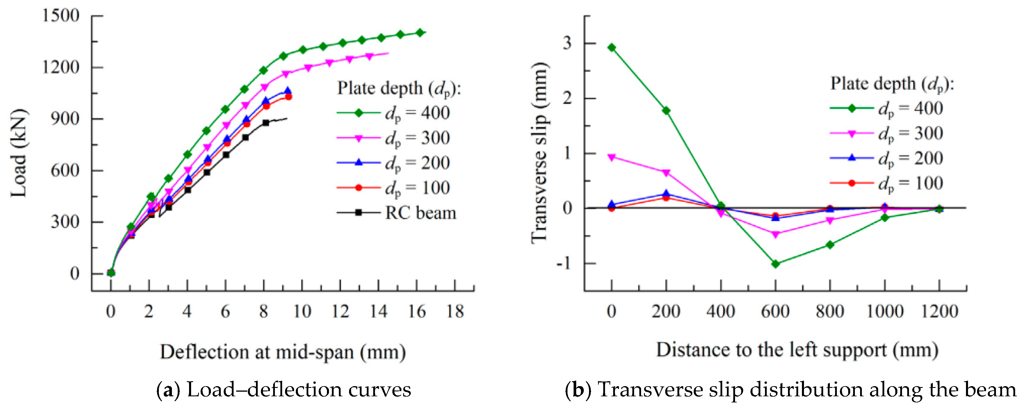
- The influence of different plate depth on the shear strengthening effect of BSP beams is shown in Figure 8. It is evident that the shear capacity, stiffness, ultimate deflection, and energy absorption increased with the plate depth. In addition, a greater plate depth caused larger transverse slip, which is because a deeper plate requires more anchor bolts to offer the same connection effect between the bolted steel plates and RC beams.
- (2)
- Thicker steel plate led to larger shear capacity, stiffness, and energy absorption as well as transverse slip.
- (3)
- When the yield strength of steel plate was larger than 300 MPa, the shear capacity, deformability, and the magnitude of transverse slip increased with the enlargement of yield strength, while that of stiffness was almost unchanged.
- (4)
- Although larger bolt diameter can raise the shear capacity, stiffness, and ultimate deflection, the improvement was negligible when the diameter was greater than 16 mm. Besides, the transverse slip decreased with the increase of bolt diameter, due to the stronger composite action between the steel plates and RC beam.
- (5)
- It is shown from Figure 9 that reducing the bolt spacing significantly improved the shear strength, stiffness, and deformability. The transverse slip decreased with an increasing bolt spacing, which was mainly caused by the better composite action.
- (6)
- The strengthening effect had little relation with the number of bolt rows (n). When n was greater than 3, the enhancement of shear performance had no evident variation. Therefore, n = 2 was a recommend number of bolt rows. The transverse slips decreased with the increasing of bolt rows.
- (7)
- Smaller shear span ratio generated larger shear bearing capacity, stiffness, and relative slips of BSP beams, while the ultimate deflection increased with the shear span ratio.
- (8)
- The increase in concrete strength resulted in greater shear bearing capacity, stiffness, deformability, and transverse slips.
- (9)
- Finally, it can be summarized that the cross-section of steel plate, bolt arrangement, shear span ratio and concrete strength affected the shear performance of BSP beams significantly. In addition, stronger bolt connection provided a reliable composite action in the steel plates and RC beam.
4. Theoretical Analysis
4.1. Shear Capacity Model Based on Deformation Compatibility
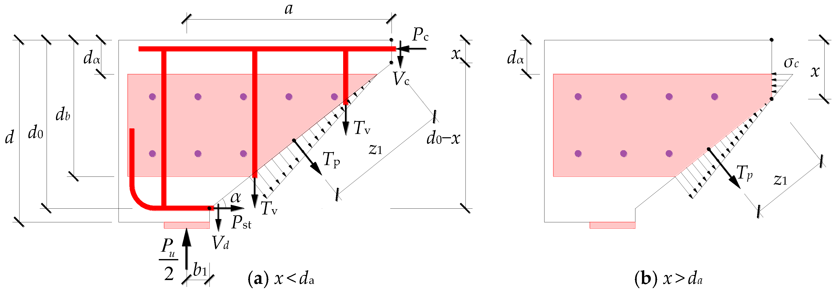
A force analysis of the beam segment in the shear span was conducted by Li et al. [24], thus a feasible analytical mode was established to evaluate the shear capacity of BSP beams, as shown in Figure 10.
The force equilibrium in the vertical direction when the BSP beam reached the ultimate limit state (when the external force P = Pu) can be expressed as:
where Tp is the tensile force of the bolted steel plates normal to the main diagonal crack, Vc is the shear force provided by concrete in the shear-compression zone near the loading point, Vd is the dowel shear force of the longitudinal tensile rebars, and Tv is the tensile force contributed from the stirrups. The depth of the shear-compression zone is x, d0 is the effective depth of the RC beam, b1 is the half width of support, a is the shear span, and α is the inclination angle of main diagonal crack.
Similarly, the mechanical equilibrium formula in the horizontal direction is:
where Pc is the compressive force of concrete in the shear-compression zone and Pst is the tensile force of the longitudinal tensile rebars.
By supposing the stress along the beam cross-section remains constant, the shear and compressive forces of concrete can be written as:
where τc and σc are the shear and compressive stresses of concrete, respectively. Asc is the cross-sectional area of longitudinal compressive rebars, b is the width of RC beam, and αE is computed as the ratio of the Young’s modulus of steel to that of concrete.
According to equivalent strength transformation principle, the dowel shear force (Vd) provided by the longitudinal tensile rebars is assumed to be provided by a nominal concrete area (αE Ast):
where fct is the tensile strength of concrete material.
The tensile force (Tv) of the shear stirrups can be computed as following:
where sv, fyv, and Asv are the longitudinal spacing, yield strength, and cross-sectional area of the stirrups, respectively.
As is shown in Figure 10, the tensile force of steel plate (Tp) is resulted from a triangular distribution of tensile stress. Considering the detrimental influence of shear lag caused by the relative slippages on the steel–concrete interface, a reduction factor (βp) with a recommended value of 0.8 is adopted in the calculation of TP as follows:
where da and db are the distance from the top surface of RC beam to the upper and lower plate edges, respectively, fyp and tp are the yield strength and thickness of the steel plate, and Ap is the inclined cross-sectional area of the steel plates corresponding to Tp.
In addition, in order to prevent the bolt group experiencing shear brittle failure prior to the tensile failure of the bolted steel plates, the shear capacity provided by the bolt group should be larger than the tensile force of the steel plate Tp (i.e., nbβpRb ≥ Tp, where nb is the number of bolts outside the main diagonal crack and Rb is the shear strength of a single bolt). The distance (z1) between the plate tensile force (Tp) and the lower edge of the shear-compression zone is as follows:
As is shown in Figure 10b, the upper area of the steel plate will be under compression when x > da. Hence, Pc, Ap, and z1 can be to be revised as follows:
Besides, the tensile force (Pst) cannot be computed according to the yield strength of the longitudinal reinforcements, because the longitudinal steel bars that pass through the shear diagonal crack might not yield. Furthermore, the deformation will be concentrated in the region around the main diagonal crack once it appears. Therefore, the assumption proposed by Barnes et al. [5] is employed, i.e., the deformation of the bolted steel plates (δp) and the longitudinal tensile rebars (δst) can be regarded as the total vertical and horizontal deformations of the beam segment in the shear span, as is shown in Figure 11.
The following expressions can be obtained based on the assumption that the breadth of the main diagonal crack stays constant along its whole length:
where εp is the strain of steel plate and εst is the strain of the longitudinal tensile rebars, thus their tensile force (Pst) can be obtained by substituting Equation (8) into Equation (11):
According to the moment equilibrium of the beam segment, the following equation can be derived by taking the moment to the lower the edge of the shear-compression zone:
In order to characterize the failure envelope of concrete in the shear-compression zone, the criterion of shear-compression strength established by Tsuboi et al. [36] is adopted:
As can be seen from Equations (1)–(14), the concrete compressive and tensile stress in the shear-compression zone can be computed as expressions in the form of x as σc(x) and τc(x). Substituting them into Equation (14) and solving this equation yields x. Finally, substituting the value of x into Equation (13) gives the shear capacity Pu. For the convenience of strengthening programming, a trial and error strategy is recommended, as shown in Figure 12:
4.2. Shear Capacity Model Based on Simplified Transverse Slip
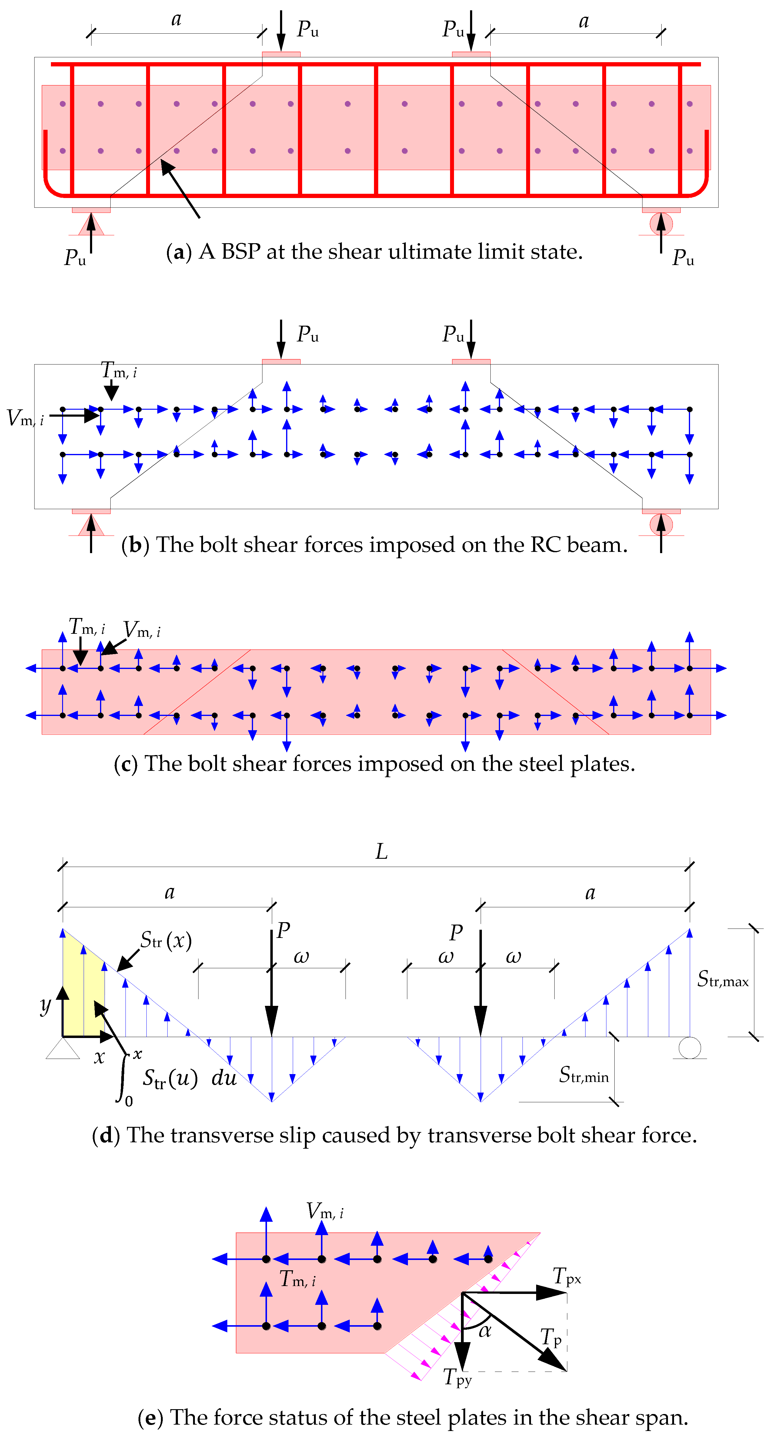
A simplified transverse slip model has been established by the authors based on the experimental and numerical results [37,38,39]. The shear ultimate limit state and the shear forces in the longitudinal and transverse directions (Tm,i & Vm,i) of a BSP beam are shown in Figure 13a–c. As is shown in Figure 13d, a piecewise linear simplified model can be introduced to depict the distribution of transverse slips [5], where Sl and Str represent the relative longitudinal and transverse slips caused by the shear forces. In addition, to ensure the anchor bolt does not experience a ductile failure, the shear stress of an anchor bolt should not exceed its yield strength. Thus, the expression between the shear forces of an anchor bolt and the transverse slip of the bolted steel plate can be written as:
where Kb is the shear stiffness of an anchor bolt. Furthermore, a consecutive shear-transfer stress of anchor bolts vm(x) can be obtained by smearing the bolt shear force (Vm, i) to the longitudinal bolt space (Sb) as following:
where Vm (x) is the total shear force provided by bolt group and Str (x) is the distribution of transverse slip, the integration is the area of the shadow region (from u = 0 to u = x) which is encircled by the distribution curves of transverse slip and the beam axis, as shown in Figure 13d.
The plate tensile force (Tp) normal to the main diagonal crack can be computed as:
According to the previous simplified assumption of a piecewise linear profile, Tp can be computed as:
where Str, max is the maximum transverse slip at the plate end.
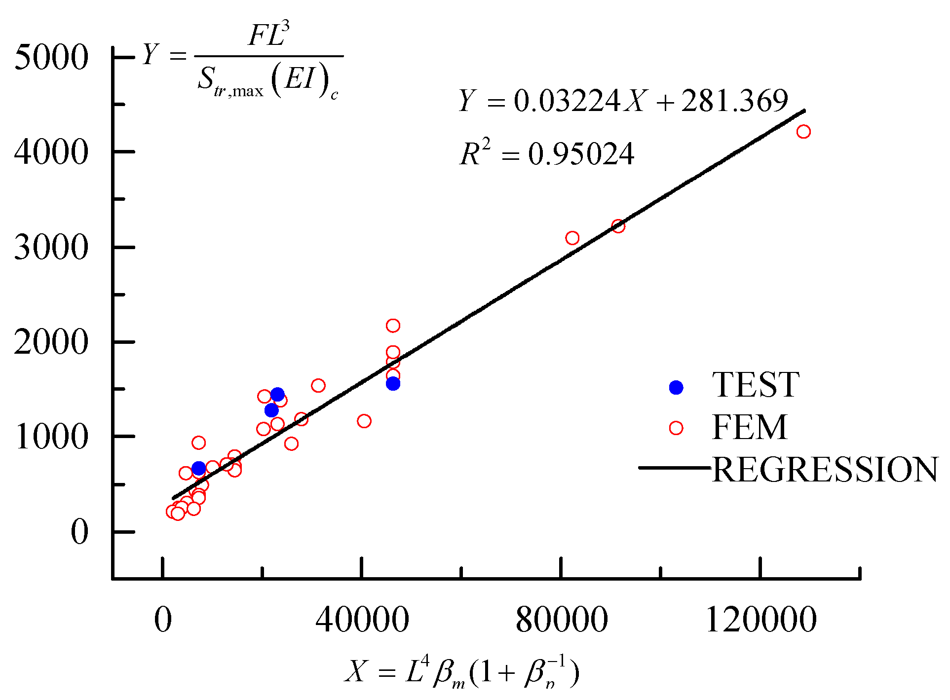
Based on previous research findings [5], the relationship between the transverse slip (Str), the external load (P), and the stiffness ratio of the steel plate (βp) and anchor bolts (βm) to the RC beam, can be computed as following:
where , , , , and C0 and C1 are the two undetermined coefficients.
The regression line and the least square fitting of the variables Y against X are plotted in Figure 14 according to the parametric study, with the undetermined coefficients C0 = 0.03224, C1 = 281.369 and the coefficient of determination R2 = 0.95024. Thus a formulation can be proposed to compute the maximum transverse slip as following:
Finally, the plate tensile force (Tp) can be obtained by substituting Equation (23) into Equation (21).
In the previous subsection, the tensile force of longitudinal rebars (Pst) was computed based on the deformation compatibility between the bolted steel plates and the tensile rebars. However, in order to simplify the calculation and make the analytical model more consistent with the actual damage pattern of an RC beam, we can suppose that the tensile reinforcement will yield when the BSP beam is under its ultimate shear limit state. Thus, the following expressions can be achieved:
where fyt is the yield strength of longitudinal tensile rebars.
Substituting Equations (5)–(7), (16), (21), and (23) into Equation (17) gives:
The expressions of τc(x) and σc(x) can be computed by Equations (4) and (5). However, instead of Equations (8) and (12), Tp and Pst should be computed by Equations (21) and (24) respectively. Substituting τc(x) and σc(x) into Equation (14) and solving the equation then yields x, and finally substituting x into Equation (25) gives the shear capacity (Pu).
Compared to the theoretical model based on the deformation compatibility of the longitudinal rebars and the bolt steel plates in the shear span, the theoretical model based on a simplified transverse slip can provide an explicit expression for the shear capacity (Pu), thus simplifying the design procedure.
4.3. Validation of the Proposed Theoretical Models
The shear bearing capacities of four BSP beams, calculated by the two proposed analytical models, were compared with the experimental results, as tabulated in Table 2. The maximum errors of the results from the theoretical models based on deformation compatibility and simplified transverse slip are 3.9% and 8.3%, respectively, and the average absolute errors are 2.7% and 5.9%, respectively. Therefore, the proposed theoretical model shows a satisfactory result, thus the feasibility of the proposed model was validated. Furthermore, the analytical model based on deformation compatibility achieved a prediction with better accuracy, but the theoretical model based on simplified transverse slip was more convenient for use, since an explicit expression for the shear capacity was given.
5. Conclusions
This paper mainly reviewed the shear performance of BSP beams from previous research conducted by the authors. The factors such as concrete strength, the cross-sectional dimensions of steel plate, shear span ratio, longitudinal bolt space, and the rows number of bolts were investigated in detail. Two feasible theoretical models, based on deformation compatibility and simplified transverse slip, were also proposed to assess the shear performance of BSP beams. Finally, a comparison between the proposed two theoretical models and the experimental results was carried out and an agreement was achieved.
Although the BSP retrofitting technique has many advantages, there are still some shortcomings, due to costs of the maintenance, durability, and anti-corrosion of the steel plate, when compared with other strengthening methods, such as FRP bonding.
Author Contributions
Conceptualization, L.-Z.L.; Data curation, X.L.; Funding acquisition, L.-Z.L. and Z.-D.L.; Investigation, X.L.; Methodology, L.-Z.L.; Supervision, L.-Z.L. and Z.-D.L.; Writing, original draft, L.-Z.L.; Writing, review& editing, L.-Z.L.
Funding
This study was supported by the Fundamental Research Funds for the Central Universities, and also funded by National Natural Science Foundation of China (Project No. 51778496, No. 51778497).
Conflicts of Interest
The authors declare no conflict of interest.
References
- Triantafillou, T.C. Shear stregthening of reinforced concrete beams using epoxy-bonded FRP composites. Struct. J. 1998, 95, 107–115. [Google Scholar]
- Deniaud, C.; Cheng, J.J.R. Shear behavior of reinforced concrete T-beams with externally bonded fiber-reinforced polymer sheets. Struct. J. 2001, 98, 386–394. [Google Scholar]
- Park, D.G.; Cho, J.Y.; Oh, B.H. Failure behavior and separation criterion for strengthened concrete members with steel plates. J. Struct. Eng. 2003, 129, 1191–1198. [Google Scholar]
- Li, L.Z.; Lo, S.H.; Su, R.K.L. Experimental study of moderately reinforced concrete beams strengthened with bolted-side steel plates. Adv. Struct. Eng. 2013, 16, 499–516. [Google Scholar] [CrossRef] [Green Version]
- Barnes, R.A.; Baglin, P.S.; Mays, G.C.; Subedi, N.K. External steel plate systems for the shear strengthening of reinforced concrete beams. Eng. Struct. 2001, 23, 1162–1176. [Google Scholar] [CrossRef]
- Adhikary, B.B.; Mutsuyoshi, H.; Sano, M. Shear strengthening of reinforced concrete beams using steel plates bonded on beam web: Experiments and analysis. Constr. Build. Mater. 2000, 14, 237–244. [Google Scholar] [CrossRef]
- Roberts, T.M.; Haji-Kazemi, H. Strengthening of under-reinforced concrete beams with mechanically attached steel plates. Int. J. Cement Compos. Lightweight Concr. 1989, 11, 21–27. [Google Scholar] [CrossRef]
- Altun, F. An experimental study of the jacketed reinforced-concrete beams under bending. Constr. Build. Mater. 2004, 18, 611–618. [Google Scholar] [CrossRef]
- Chalioris, C.E.; Thermou, G.E.; Pantazopoulou, S.J. Behaviour of rehabilitated RC beams with self-compacting concrete jacketing—Analytical model and test results. Constr. Build. Mater. 2014, 55, 257–273. [Google Scholar] [CrossRef]
- Yu, K.Q.; Li, L.Z.; Yu, J.T.; Xiao, J.Z.; Ye, J.H.; Wang, Y.C. Feasibility of using ultra-high ductility cementitious composites for concrete structures without steel rebar. Eng. Struct. 2018, 170, 11–20. [Google Scholar] [CrossRef]
- Ombres, L.; Verre, S. Shear Performance of FRCM Strengthened RC Beams. Spec. Publ. 2018, 324, 7.1–7.22. [Google Scholar]
- Gao, W.Y.; Dai, J.G.; Teng, J.G. Fire resistance design of un-protected FRP-strengthened RC beams. Mater. Struct. 2016, 49, 5357–5371. [Google Scholar] [CrossRef]
- Aram, M.R.; Czaderski, C.; Motavalli, M. Debonding failure modes of flexural FRP-strengthened RC beams. Compos. Part B 2008, 39, 826–841. [Google Scholar] [CrossRef]
- Sas, G.; Carolin, A.; Täljsten, B. A model for predicting the shear bearing capacity of FRP-strengthened beams. Mech. Compos. Mater. 2008, 44, 245–256. [Google Scholar] [CrossRef]
- Yu, J.T.; Liu, K.K.; Li, L.Z.; Wang, Y.C.; Yu, K.Q.; Xu, Q.F. A simplified method to predict the fire resistance of RC Beams strengthened with near-surface mounted CFRP. Compos. Struct. 2018, 193, 1–7. [Google Scholar] [CrossRef]
- Hawileh, R.; Rami, A.; Abdalla, J.A.; Tanarslan, M.; Naser, M.Z. Modeling of nonlinear cyclic response of shear-deficient RC T-beams strengthened with side bonded CFRP fabric strips. Comput. Concr. 2011, 8, 193–206. [Google Scholar] [CrossRef]
- Hassan, T.K.; Tarek Rizkalla, S.H. Flexural strengthening of prestressed bridge slabs with FRP systems. Pci J. 2002, 47, 76–93. [Google Scholar] [CrossRef]
- Yu, J.T.; Wang, Y.C.; Zhan, K.L.; Li, L.Z.; Yu, K.Q. Using XFEM to model the effect of different axial compression on the hysteretic behaviour of the flexure-dominant RC columns. Struct. Des. Tall Spec. 2018, e1465. [Google Scholar] [CrossRef]
- Hawileh, R.; Abdalla, J.A.; Naser, M.Z.; Tanarslan, M. Finite element modeling of shear deficient RC beams strengthened with NSM CFRP rods under cyclic loading. Spec. Publ. 2015, 301, 1–18. [Google Scholar]
- Rizkalla, S.H.; Hassan, T.K.; Lucier, G. FRP Shear Transfer Mechanism for Precast, Prestressed Concrete Sandwich Load-Bearing Panels. Spec. Publ. 2009, 265, 603–625. [Google Scholar]
- Su, R.K.L.; Zhu, Y. Experimental and numerical studies of external steel plate strengthened reinforced concrete coupling beams. Eng. Struct. 2005, 27, 1537–1550. [Google Scholar] [CrossRef] [Green Version]
- Alam, M.A.; Jumaat, M.Z. Eliminating premature end peeling of flexurally strengthened reinforced concrete beams. J. Appl. Sci. 2009, 9, 1106–1113. [Google Scholar] [CrossRef]
- Oehlers, D.J.; Ahmed, M.; Nguyen, N.T.; Bradford, M.A. Retrofitting reinforced concrete beams by bolting steel plates to their sides. Part 2: Transverse interaction and rigid plastic design. Struct. Eng. Mech. 2000, 10, 227–243. [Google Scholar] [CrossRef]
- Li, L.Z.; Cai, Z.W.; Lu, Z.D.; Zhang, X.L.; Wang, L. Shear performance of bolted side-plated reinforced concrete beams. Eng. Struct. 2017, 144, 73–87. [Google Scholar] [CrossRef]
- Su, R.K.L.; Li, L.Z.; Lo, S.H. Shear transfer in bolted side-plated reinforced concrete beams. Eng. Struct. 2013, 56, 1372–1383. [Google Scholar] [CrossRef] [Green Version]
- Jiang, C.J.; Lu, Z.D.; Li, L.Z. Shear performance of fire-damaged reinforced concrete beams repaired by a bolted side-plating technique. J. Struct. Eng. ASCE 2017, 143, 4017007. [Google Scholar] [CrossRef]
- Li, L.Z.; Jiang, C.J.; Liu, B.Z.; Lu, Z.D. Shear strengthening of fire-damaged reinforced concrete beams using bolted-side plating. Procedia Eng. 2017, 210, 186–195. [Google Scholar] [CrossRef]
- Li, L.Z.; Jiang, C.J.; Jia, L.J.; Lu, Z.D. Local buckling of bolted steel plates with different stiffener configuration. Eng. Struct. 2016, 119, 186–197. [Google Scholar] [CrossRef]
- Su, R.K.L.; Li, L.Z.; Lo, S.H. Longitudinal partial interaction in bolted side-plated reinforced concrete beams. Adv. Struct. Eng. 2014, 17, 921–936. [Google Scholar] [CrossRef]
- Lo, S.H.; Li, L.Z.; Su, R.K.L. Optimization of partial interaction in bolted side-plated reinforced concrete beams. Comput. Struct. 2014, 131, 70–80. [Google Scholar] [CrossRef]
- Xu, X.L.; Lu, Z.D.; Li, L.Z.; Jiang, C.J. Numerical study on the local buckling behaviour of bolted steel plates in steel jacketing. Adv. Mater. Sci. Eng. 2017, 2017, 1352084. [Google Scholar] [CrossRef]
- Li, L.Z.; Wu, Z.L.; Yu, J.T.; Wang, X.; Zhang, J.X.; Lu, Z.D. Numerical simulation of the shear capacity of bolted side-plated RC beams. Eng. Struct. 2018, 171, 373–384. [Google Scholar] [CrossRef]
- Xie, L.; Lu, X.; Lu, X.; Huang, Y.; Ye, L. Multi-layer shell element for shear walls in OpenSees. In Proceedings of the International Conference on Computing in Civil and Building Engineering, Orlando, FL, USA, 23–25 June 2014; pp. 1190–1197. [Google Scholar]
- Faria, R.; Pouca, N.S.V.; Delgado, R. Simulation of the cyclic behaviour of R/C rectangular hollow section bridge piers via a detailed numerical model. J. Earthq. Eng. 2004, 8, 725–748. [Google Scholar] [CrossRef]
- Wang, L.; Liu, Z.; Zhang, X. Global Dynamics of an Sveir Epidemic Model With Distributed Delay and Nonlinear Incidence; Elsevier Science Inc.: Amsterdam, The Netherlands, 2016. [Google Scholar]
- Tsuboi, Y.; Tanaka, H.; Suenaga, Y. A study on failure of reinforced concrete members under combined stresses (part 4): Especially on beam under bending moment and shearing force. Trans. Archit. Inst. Jpn. 1961, 67, 1–9. [Google Scholar] [CrossRef]
- Li, L.Z.; Jiang, C.J.; Su, R.K.L.; Lo, S.H. Design of bolted side-plated reinforced-concrete beams with partial interaction. Struct. Build. 2016, 169, 81–95. [Google Scholar] [CrossRef]
- Li, L.Z.; Jiang, C.J.; Su, R.K.L.; Lo, S.H. A piecewise linear transverse shear transfer model for bolted side-plated beams. Struct. Eng. Mech. 2017, 62, 443–453. [Google Scholar] [CrossRef]
- Smith, S.T.; Bradford, M.A.; Oehlers, D.J. Buckling tests on steel plates restrained at discrete points in the retrofit of reinforced concrete beams. Proc. ICE-Struct. Build. 2001, 146, 115–127. [Google Scholar] [CrossRef]
Figure 1.
Details of reinforcement and bolted side-plating (BSP) strengthening (dimensions in mm).
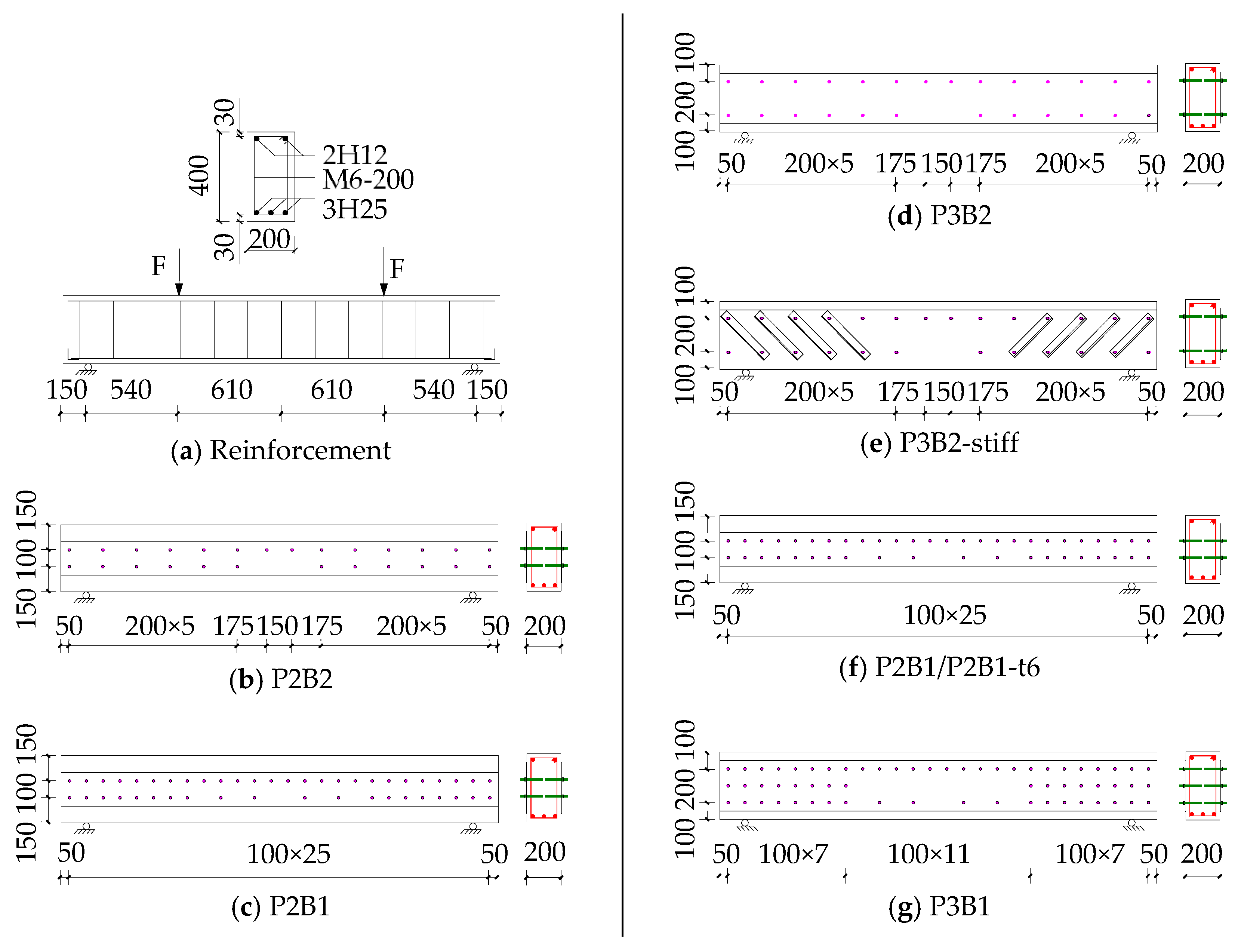
Figure 2.
Schematic diagram of test set-up and the instruments.
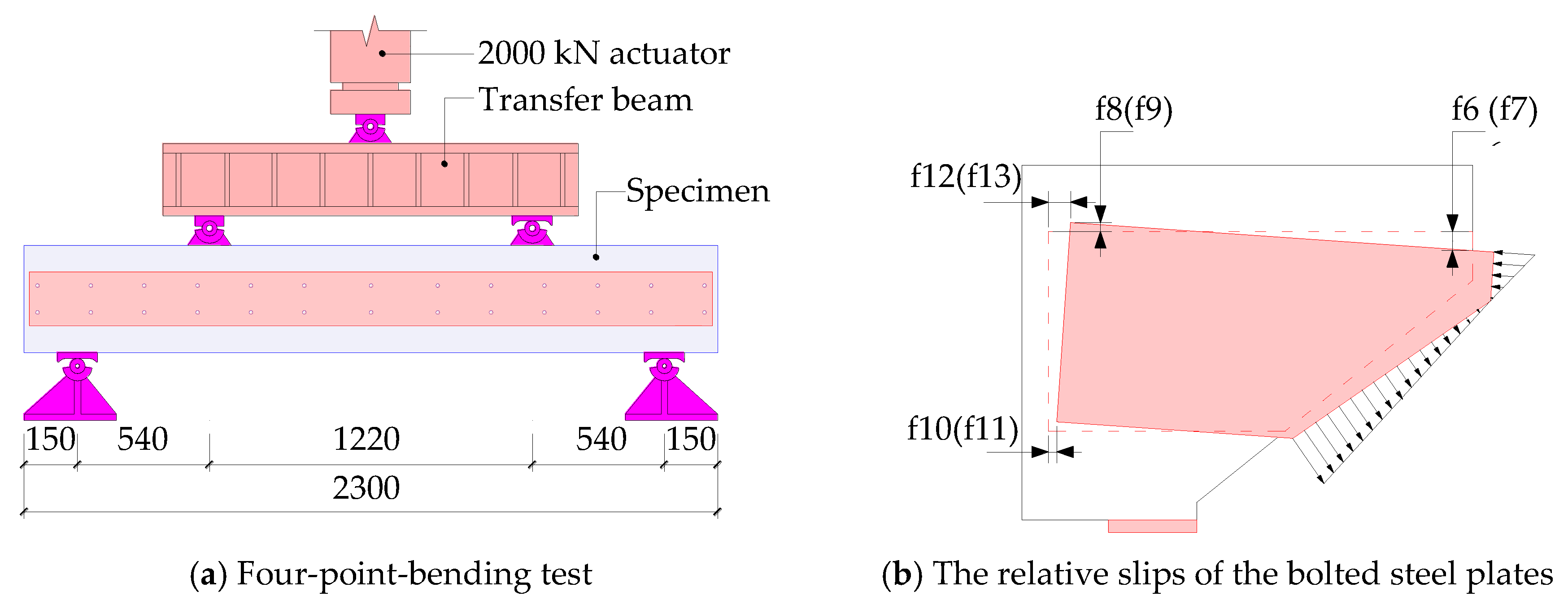

Figure 3.
Comparison of load–vertical displacement curves.

Figure 4.
The relative slips in the shear span of specimen P3B2-stiff.
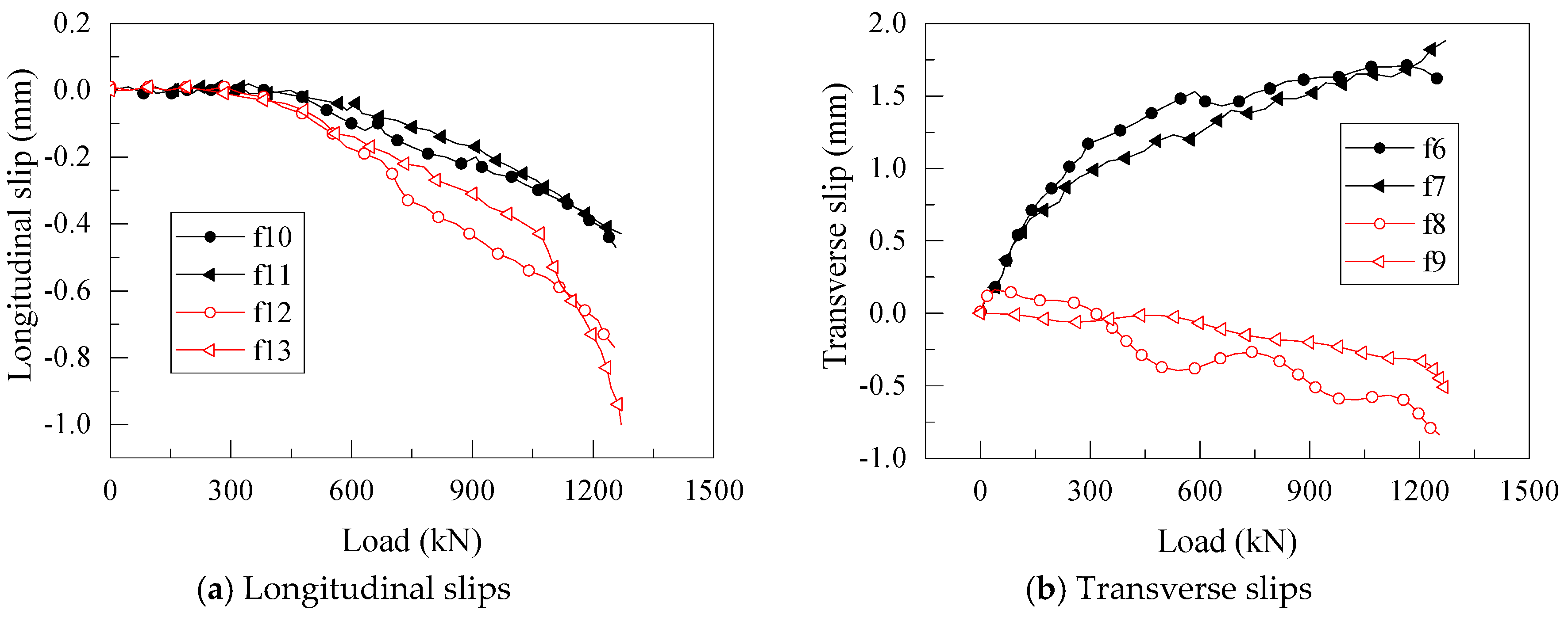
Figure 5.
Simulation of bolt connection in BSP beams.
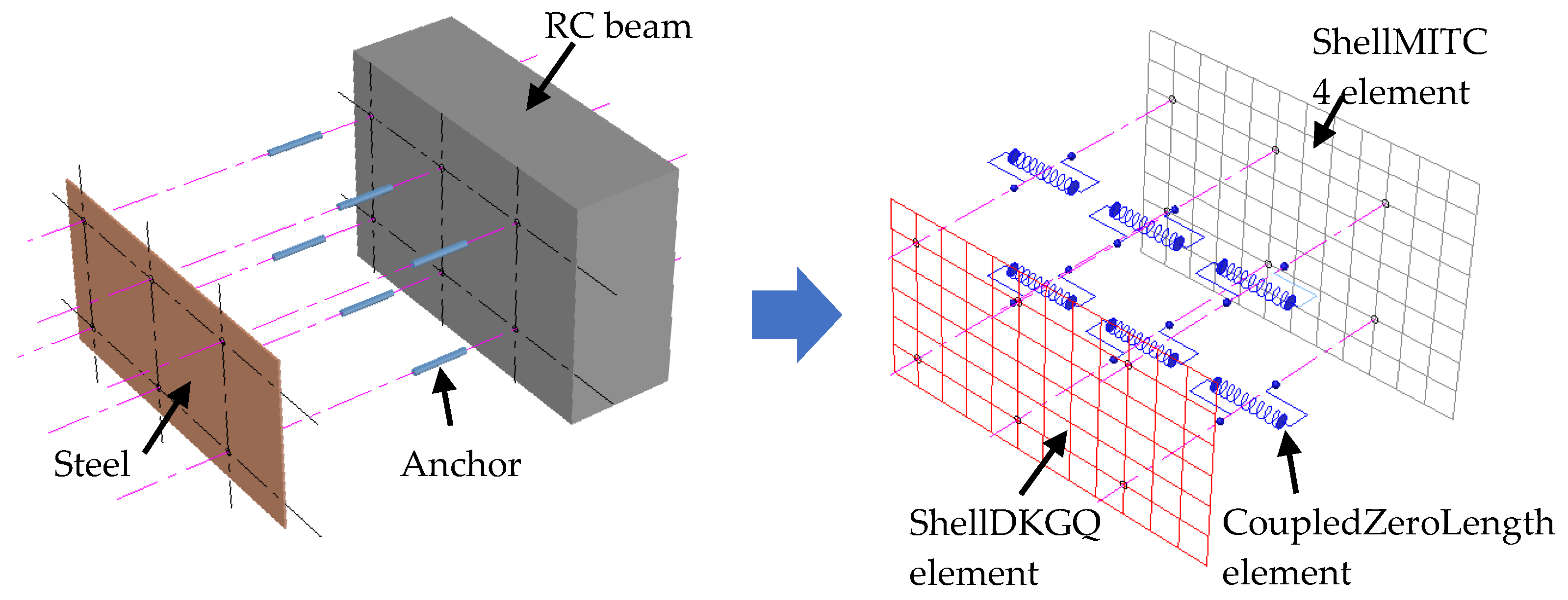
Figure 6.
Comparison of the experimental and numerical failure modes.
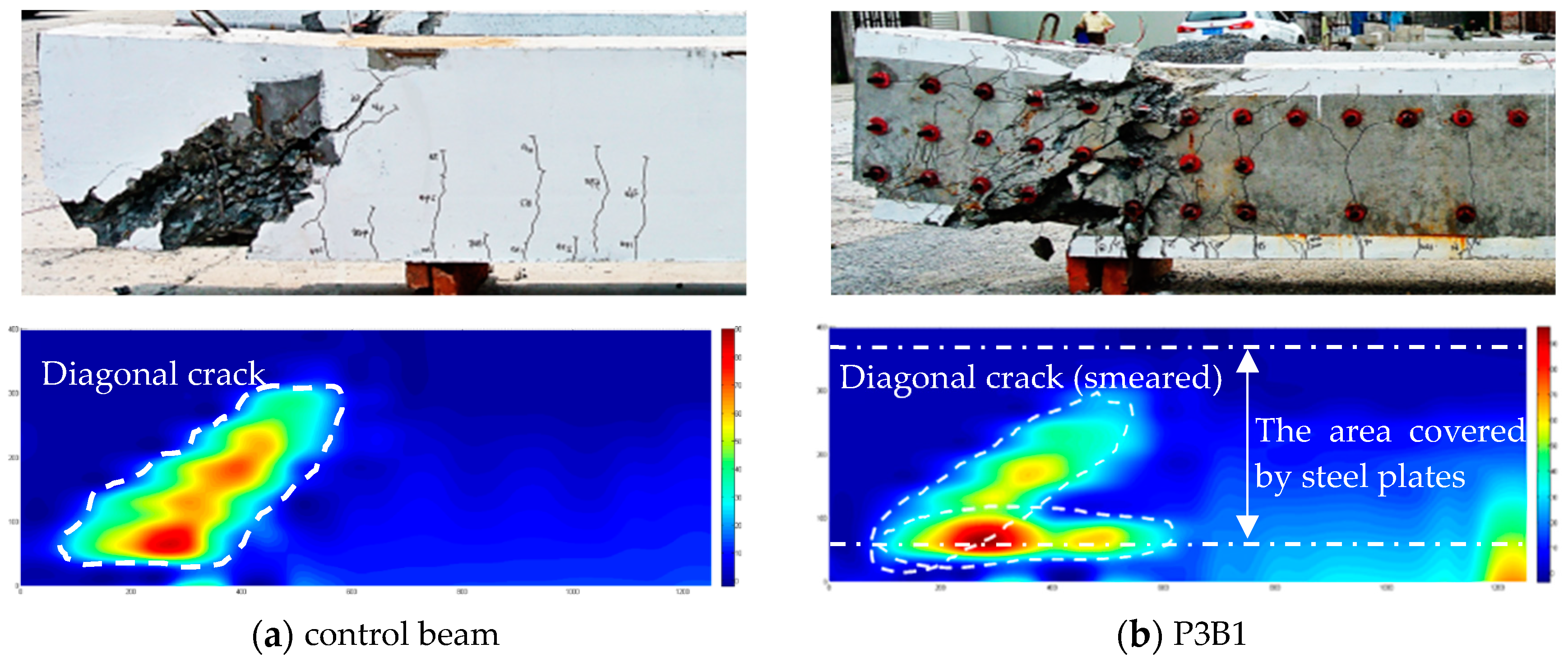
Figure 7.
Comparison of the experimental and numerical load-deflection curves.
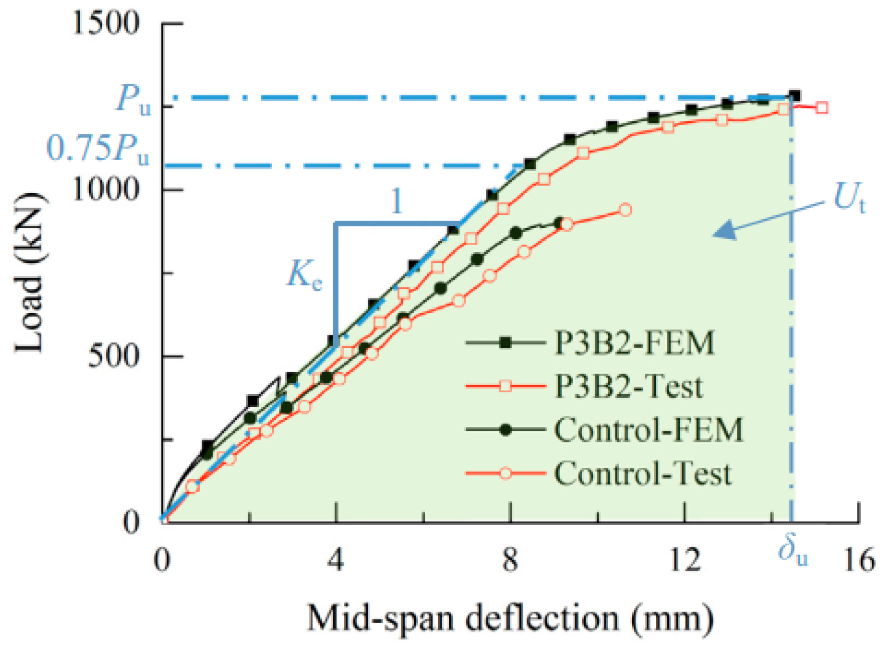
Figure 8.
Shear behavior of BSP beams with various plate depth (dp).

Figure 9.
Shear responses of BSP beams repaired with various horizontal bolt spacing (Sb).
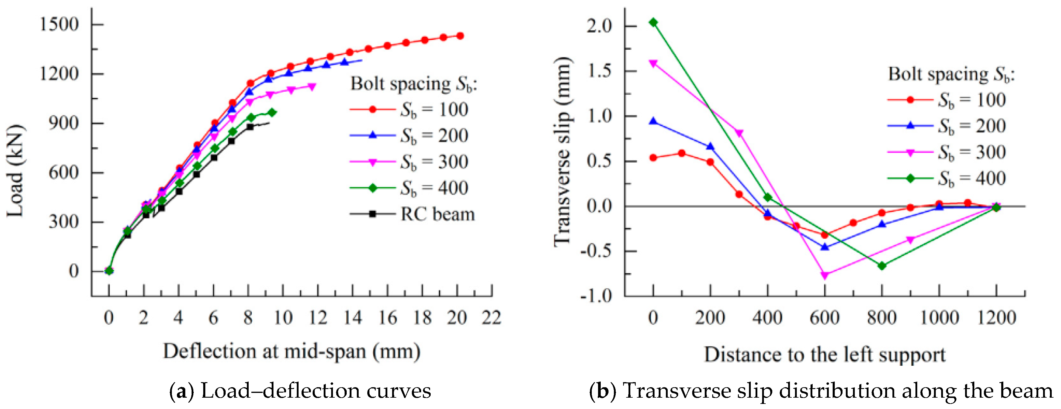
Figure 10.
Forces and stress profile of the beam segment in the shear span.

Figure 11.
Shear deformation of the shear segment.
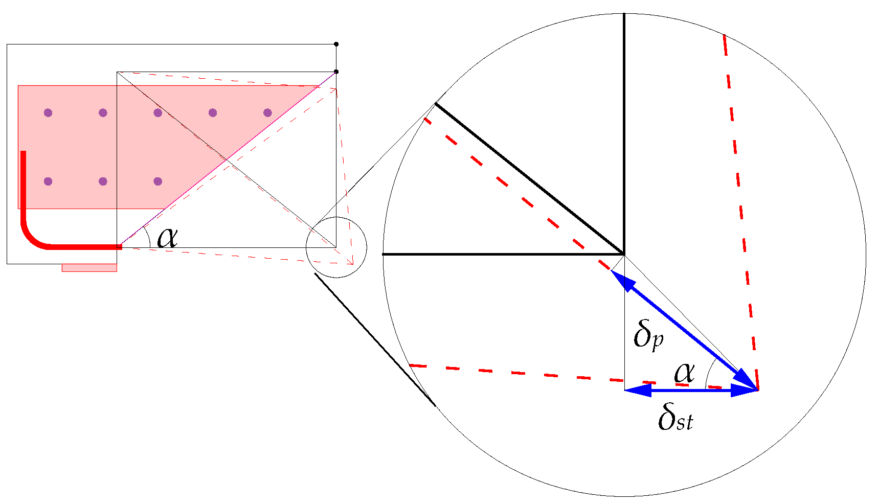
Figure 12.
The strengthening programming procedure based on trial and error technique.

Figure 13.
General view of shear forces and transverse slips.

Figure 14.
Data fitting of test and simulation result.

Table 1.
Comparison of the shear capacity and ultimate displacement derived from the experimental and numerical studies.
Table 1.
Comparison of the shear capacity and ultimate displacement derived from the experimental and numerical studies.
| Specimen | Shear Capacity (kN) | Ultimate Displacements (mm) | ||||
|---|---|---|---|---|---|---|
| Experimental | Numerical | Error | Experimental | Numerical | Error | |
| Control | 947 | 902.2 | −5.8% | 10.6 | 9.3 | 13.7% |
| P3B1 | 1409 | 1443.1 | 2.1% | 22.6 | 20.3 | 10.0% |
| P3B2 | 1260 | 1282.6 | 1.7% | 15.2 | 14.5 | 4.6% |
| P2B1 | 1174 | 1098.3 | −6.7% | 11.9 | 10.6 | 11.0% |
| P2B2 | 1090 | 1043.8 | −4.3% | 10.8 | 9.4 | 13.3% |
| Average absolute error: | 4.2% | Average absolute error: | 10.5% | |||
Table 2.
Comparison between the proposed analytical models and experimental results.
| Sample | Shear Capacity (kN) | Error | |||
|---|---|---|---|---|---|
| Experimental Pu,exp | Theoretical Model 1 Pu,the 1 | Theoretical Model 2 Pu,the 2 | |||
| P3B1 | 1409 | 1362 | 1513 | −3.3% | 7.4% |
| P3B2 | 1260 | 1218 | 1312 | −3.3% | 4.1% |
| P2B1 | 1174 | 1128 | 1076 | −3.9% | −8.3% |
| P2B2 | 1090 | 1101 | 1051 | −0.3% | −3.6% |
| Average absolute error: | 2.7% | 5.9% | |||
© 2018 by the authors. Licensee MDPI, Basel, Switzerland. This article is an open access article distributed under the terms and conditions of the Creative Commons Attribution (CC BY) license (http://creativecommons.org/licenses/by/4.0/).
Share and Cite
MDPI and ACS Style
Liu, X.; Lu, Z.-D.; Li, L.-Z. The Use of Bolted Side Plates for Shear Strengthening of RC Beams: A Review. Sustainability 2018, 10, 4658. https://doi.org/10.3390/su10124658
AMA Style
Liu X, Lu Z-D, Li L-Z. The Use of Bolted Side Plates for Shear Strengthening of RC Beams: A Review. Sustainability. 2018; 10(12):4658. https://doi.org/10.3390/su10124658
Chicago/Turabian StyleLiu, Xin, Zhou-Dao Lu, and Ling-Zhi Li. 2018. "The Use of Bolted Side Plates for Shear Strengthening of RC Beams: A Review" Sustainability 10, no. 12: 4658. https://doi.org/10.3390/su10124658
Note that from the first issue of 2016, this journal uses article numbers instead of page numbers. See further details here.