1. Introduction
Owing to the increasing concerns regarding the emerging problems of energy crisis and environmental pollution, the discussion on hybrid electric vehicles (HEVs) has drawn much attention [
1,
2,
3,
4]. Serving as one of the key components of the HEV system, electric machines should be able to fulfill several criteria including [
5,
6,
7,
8]:
In the past years, various electric machine types, including the induction machine, switched reluctance (SR) machine, and interior permanent-magnet (IPM) machine have been developed for HEV applications [
9]. However, each of these machines suffers from its own demerits. For instance, the induction machine generally suffers from low power density [
10], the SR machine from low efficiency [
11], and the IPM machine from a large torque ripple [
12]. On the other hand, the switched-flux permanent-magnet (SFPM) machine might be able to fulfill the mentioned requirements, and this type of machine has become the major research stream in the past years [
13,
14,
15]. The partitioned-stator SFPM (PS-SFPM) machine, which utilizes the inner space to improve machine performances, has been proposed recently [
16]. Nevertheless, the same as the other PM machines, the PS-SFPM machine also suffers from undesirable flux-weakening performance.
To provide a better flux-weakening capability, the concept of the external flux adjuster (FA) has been developed [
17,
18,
19]. With the installation of mechanical FAs, the PM flux density can be short-circuited and weakened to a desirable level. However, the implementation of the mechanical FA arrangement suffers from its complicated structure. To improve the situation and to maintain the simplicity of the machine structure, the development of dual-excitation (DE) machines has been regarded as a promising solution [
20,
21]. In Reference [
19], the proposed DE machine installs its DC-field winding together with high-energy-density PM accommodation, and hence sacrifices some of its PM material space for DC-field winding installation. Consequently, its entire potential regarding power and torque densities are not fully reached. Further discussion on the DE machine with another DC-field winding position would be of great interest.
The purpose of this paper is to propose a new type of PS-SFDE machine for the HEV industry. Unlike the established PS-SFDE machine, which sacrifices high-energy-density PM materials for DC-field winding accommodations, the proposed machine instead shares the space of the armature winding with the DC-field winding. Hence, comparable power and torque densities can be generated. To show the attractiveness of the proposed PS-SFDE machine, the PS-SFPM, the FA-PS-SFPM, and the renowned Toyota Prius HEV machine will be analyzed and compared.
2. Partitioned-Stator Machines
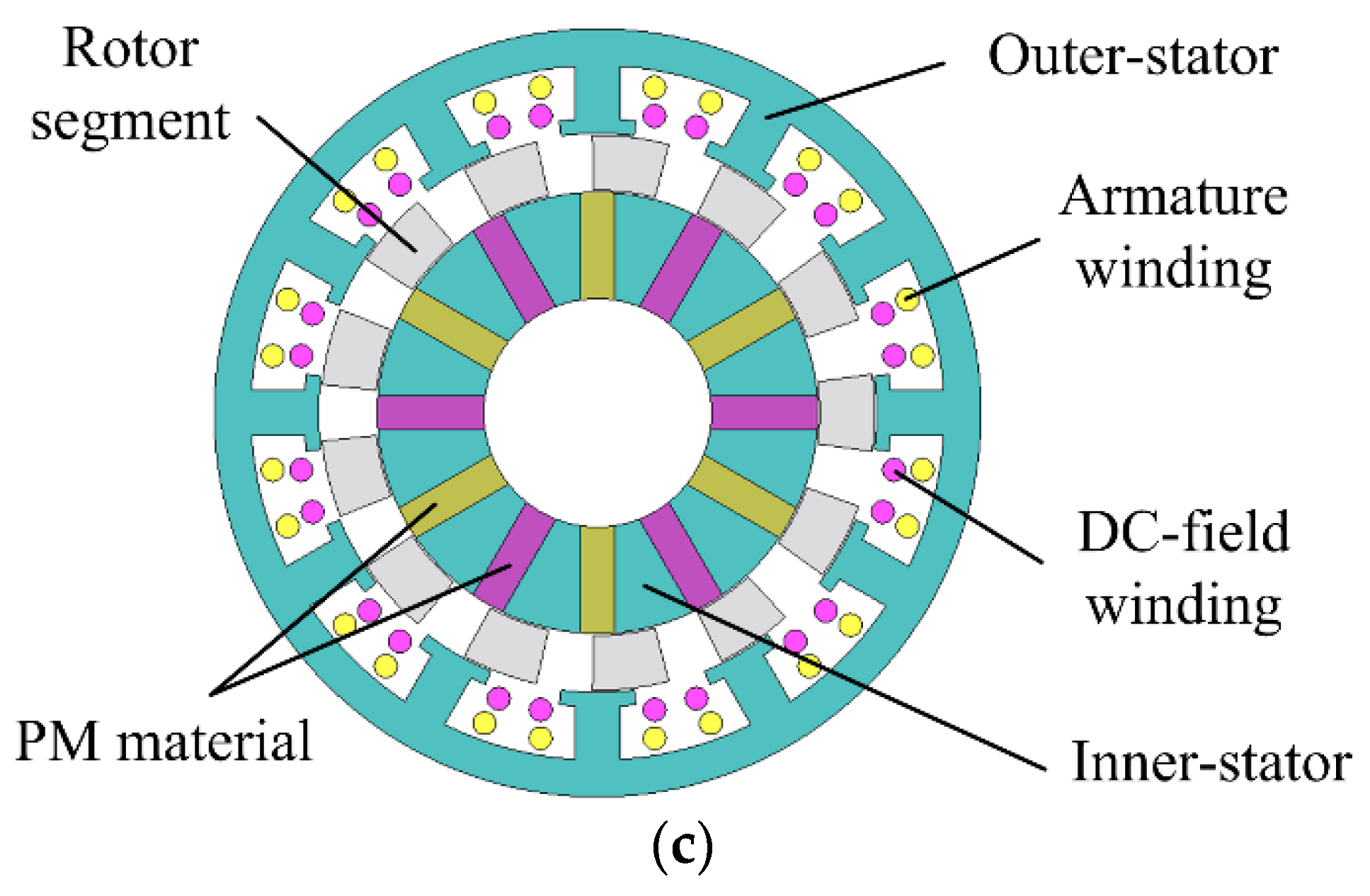
The PS-SFPM machine, the FA-PS-SFPM machine, and the PS-SFDE machine are shown in
Figure 1. Unlike the previous design that employs the common pole-pair combination, i.e., twelve-stator-slots ten-rotor-poles [
19], the proposed machines instead employ relatively less common pole-pair combinations, i.e., three-phase twelve-stator-slots thirteen-rotor-poles. With this pole-pair arrangement, a smaller torque ripple pulsation can be potentially achieved [
22]. To have a fair comparison, all three machines are design based on the machine structure, i.e., the dual-stators sandwiched-rotor structure. To avoid magnetic saturation within a particular region, the armature windings and the PM materials are purposely installed in the outer-stator and the inner-stator separately. Since the three machines are the extension from the profound SFPM machine, their key design equations such as the pole arrangements can be derived from that of its ancestors [
13]. The three proposed machines consist of the unique flux-weakening arrangements, i.e., (i) the PS-SFPM machine can weaken its flux density based on its armature currents; (ii) the FA-PS-SFPM machine on the mechanical FA installation; and (iii) the PS-SFDE machine on the independent DC-field currents.
Unlike the PS-SFDE machine that places its DC-field windings within the same spaces as the high-energy-density PM pieces [
19], the proposed PS-SFDE machine instead installs its DC-field windings within same spaces as the armature windings. In the previous design, some of the potential spaces for PM accommodation were sacrificed for DC-field winding, and hence its power and torque densities were degraded. In the proposed design, the DC-field winding no longer shares any space with PM materials and this topology enables the machine to boost its power and torque densities to their limits. As a result, the proposed machine can potentially provide satisfactory power and torque densities, even when compared with its PS-SFPM counterpart.
The three proposed machines, namely the PS-SFPM, the FA-PS-SFPM, and the PS-SFDE machines are developed with respect to the passenger HEV requirements [
14]. To offer a more comprehensive comparison, the popular Prius HEV machine is also taken into account as a benchmark. To fairly compare all of these machines, their most important parameters are chosen to be the same.
3. Principle of Operations
To explain the operating principles of the three machines, the PM field paths of the PS-SFPM machine are shown in
Figure 2. Not surprisingly, the proposed machines illustrate equal field path patterns, i.e., if the machine rotates at a 180 electrical angle, its field direction is reversed correspondingly. As a result, all the SF machines can produce bipolar flux-linkage patterns, and these machines can potentially generate better power and torque than the unipolar machines [
7].
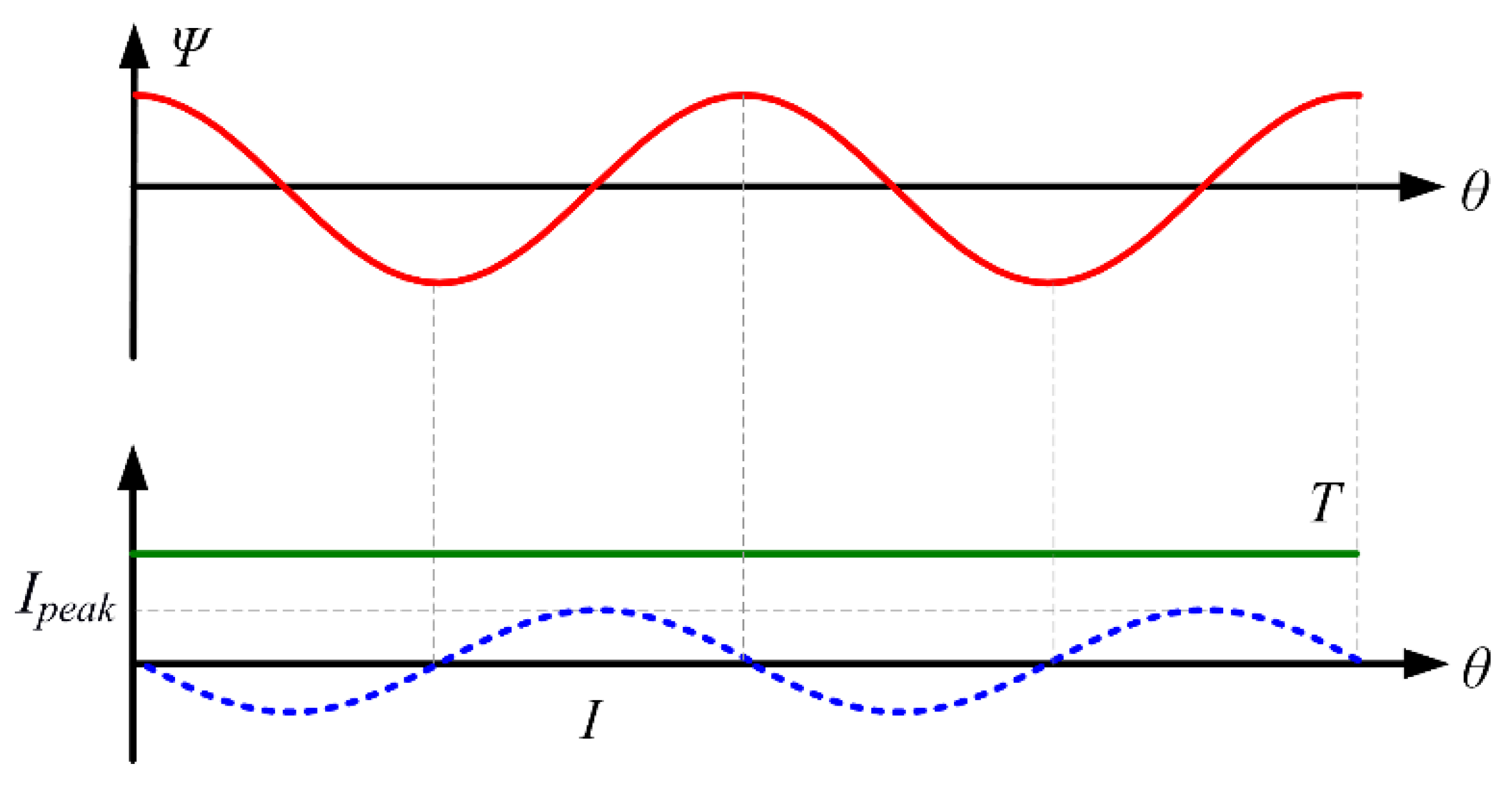
Because all of the SF machines are developed from fundamental SFPM ancestors, they can also be powered with some profound operating schemes [
6]. In particular, the armature current
I is injected regarding the status of their flux-linkages
Ψ. Consequently, the resultant torque
T is produced. This operating scheme is generally known as brushless AC (BLAC) operation, as shown in
Figure 3. Upon the application of the BLAC operation, the proposed machines are able to seamlessly interact with their corresponding employed armature currents, and hence the undesirable torque ripple problem can be minimized. The BLAC operation can be achieved when the corresponding armature currents are
where
i and
Ipeak are the corresponding armature currents and the maximum value of the armature currents, respectively.
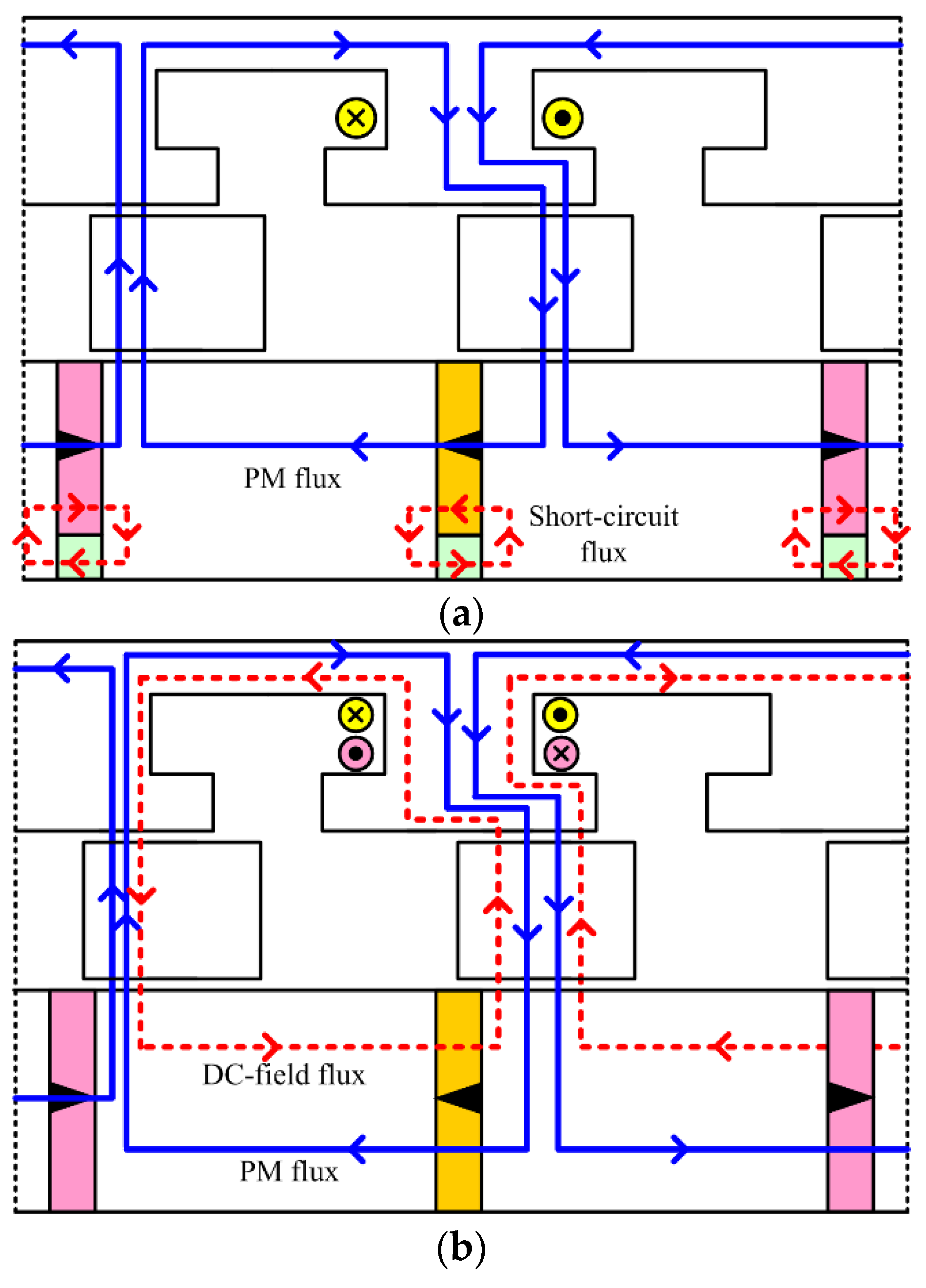
As previously mentioned, the three proposed machines can weaken their PM flux densities with their distinguished approaches. In particular, the PS-SFPM machine can weaken its PM field by regulating its armature currents. Meanwhile, the FA-SFPM machine can utilize the mechanical FAs to short-circuit the PM field, as shown in
Figure 4a. As a result, the FA-SFPM machine can provide an outstanding flux-weakening capability. On the other hand, the hybrid PS-SFDE machine can independently control its DC-field currents to weaken its PM field density, as shown in
Figure 4b. Consequently, the hybrid machine can offer both a satisfactory PM flux density and reasonable flux-weakening capability simultaneously.
4. Numerical Approach
The numerical approach is generally accepted as a very useful method to analyze machine performances [
6]. To develop machine models, three equation sets are described. The first one is the electromagnetic field equation as [
23]:
where
v is reluctivity,
A is vector potential component, and
J is current density. The second equation set is the circuit equation during motoring as:
where
u is applied voltage,
R is winding resistance,
L is end-winding inductance,
e is electromotive force (EMF),
l is axial length,
S is cross-sectional area of conductor, and Ω
s is sum of the cross-sectional area of conductor. The final equation set is the motion equation as:
where
Jm is moment of inertia,
ω is operating speed,
TL is load torque, and
λ is damping coefficient. To analyze the machine performances, a well-defined finite element method (FEM) software is employed. With the iterative approaches, the optimization of the key machine parameters can be achieved. To make a fair comparison, the key machine parameters, namely outer-stator outside diameters, airgap lengths, stack lengths, winding fill factors, and current densities are set as equal. Consequently, all three proposed machines can be compared quantitatively in a fair environment. The Prius HEV machine is also included for illustration purposes, while their key design data is listed in
Table 1.
The magnetic flux distributions of the proposed machines at no-load conditions are shown in
Figure 5. It can be seen that the magnetic flux distributions of the proposed machines consist of very uniform patterns and with no obvious saturations. It can then be anticipated that the machine parameters have been optimized throughout iteration. As a result, it can be suggested that the machines are able to achieve their corresponding optimum performances, in terms of efficiencies and losses.
5. Machine Performance Analysis
5.1. Machine Performance at No-Load Conditions
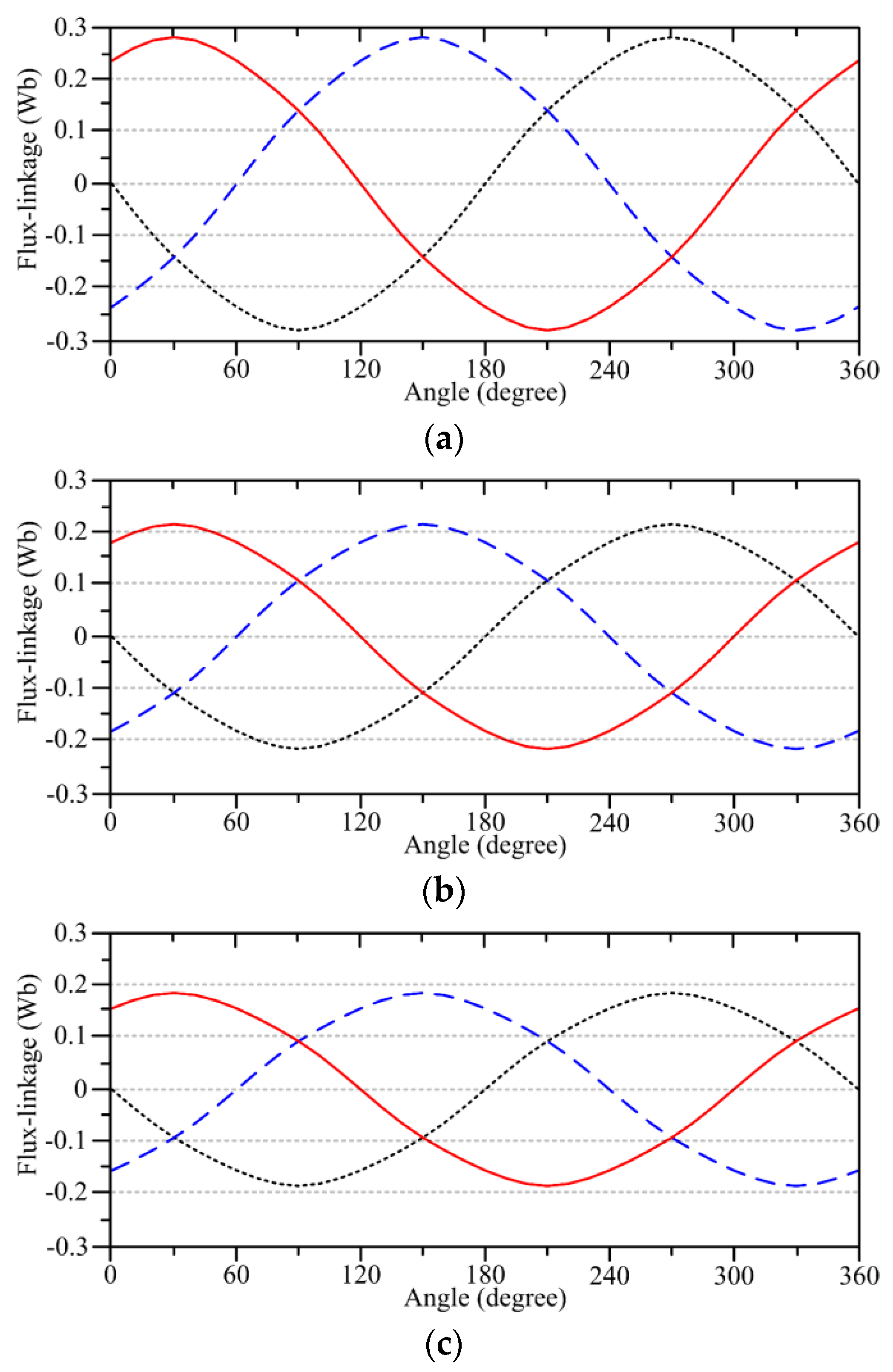
The flux-linkage waveforms of the proposed machines are shown in
Figure 6. Since all three machines consist of the same operating principles, their flux-linkage patterns are very similar. In particular, the three machines can all produce flux-switching performances. As shown, the PS-SFPM machine exhibits the greatest flux-linkage magnitudes and hence should be able to produce the largest power and torque levels among the group.
5.2. Torque Performance Analysis
The output torque waveforms of the proposed machines are shown in
Figure 7. It should be noted that the PS-SFPM machine can only utilize the armature excitations for the flux-regulating operation, and its steady torque can reach up to 385 Nm. In the meantime, the FA-PS-SFPM machine in different scenarios, namely without any FAs, with only half FAs, and with full FAs, are about 376 Nm, 271 Nm, and 192 Nm, respectively. In addition, the PS-SFDE machine under three situations, namely with
IDC = 0 A/mm
2,
IDC = −15 A/mm
2, and
IDC = −30 A/mm
2, are about 351 Nm, 309 Nm, and 293 Nm, respectively.
Moreover, the torque ripple percentage
Kripple can be calculated based on the following relationship:
where
Tavg,
Tmax, and
Tmin are the average, maximum, and minimum torque values, respectively. It is shown that the torque pulsation of the PS-SFPM machine is about 5.3%. The torque pulsation of the FA-PS-SFPM machine under corresponding situations are about 6.2%, 9.8%, and 13.4%, while those of the PS-SFDE machine are about 6.1%, 9.6%, and 12.8%.
In addition, the cogging torques of the proposed machines are shown in
Figure 7. It is shown that the cogging torque of the PS-SFPM machine is about 16.2 Nm, which is around 4.2% of its rated torques. The cogging torques of the FA-PS-SFPM machine are 14.5 Nm, 6.3 Nm, and 4.1 Nm, as 3.9%, 2.3%, and 2.1% of its rated torques. For the PS-SFDE machine, its cogging torques are 13.8 Nm, 6.9 Nm, and 5.7 Nm, as 3.9%, 2.2%, and 1.9% of its rated torques.
5.3. Flux-Weakening Performance Analysis
The flux-weakening performances of the PS-SFDE and the FA-PS-SFPM machines are calculated, while their no-load EMF waveforms with respect to various operating speeds are shown in
Figure 8. With the employment of the external FAs, it can be shown that the FA-PS-SFPM machine can weaken its no-load EMF values by about 47%. In the meantime, if its DC-field windings are injected with negative polarity, i.e.,
IDC = −30 A/mm
2, the PS-SFDE machine can only weaken its no-load EMF values by about 18%. As a result, it can be shown that the proposed FA-PS-SFPM machine can provide greater flux-weakening capability than the PS-SFDE machine does.
6. Evaluations on Key Criteria
The major machine performances are listed in
Table 2. As a key factor for HEV applications, the machine weight should be taken into consideration. While all machines consist of different weights, their differences are less than 4%. Provided that all key machine parameters are set as equal, it can be assumed that all machines can be compared fairly. The aim of this paper is to compare four proposed machines quantitatively and qualitatively, while the evaluations can still be applicable to other machine types. In particular, some quantitative figures, such as efficiency, power density, torque density, power per cost, torque per cost, can be utilized for objective comparisons. To further show the distinctive merits of the developed machines, the popular Prius HEV machine is utilized to serve as a benchmark.
With substantial installation of high-energy-density PM materials, the proposed PS-SFPM machine is able to provide the greatest torque and power levels within the comparisons. As a result, this machine is highly attractive for high-performance users.
Nevertheless, the PM sources are limited and hence the construction costs of the PM machine have become the dominating part for prototyping [
24]. Undoubtedly, the cost-effectiveness must be one of the most important factors that interferes with the HEV market value, such that it should be considered carefully. In particular, the key material costs can be deduced by its raw material costs. It should be noted that the Prius machine can provide the best cost-benefit within the peer group, and it becomes one of the key reasons why this machine type is so popular in the HEV market.
Controllability and reliability are two of the most important criteria for HEV applications. Since the four studied machines all employ the conventional BLAC conduction scheme, all of them share a similar level of controllability. For reliability, because all of these machines are designed based on similar protocols, e.g., same voltage limits, same current densities, same cooling devices, etc., all of them should share similar reliabilities. However, because of additional mechanical FA installations, the FA-PS-SFPM machine is relatively less reliable than its counterparts.
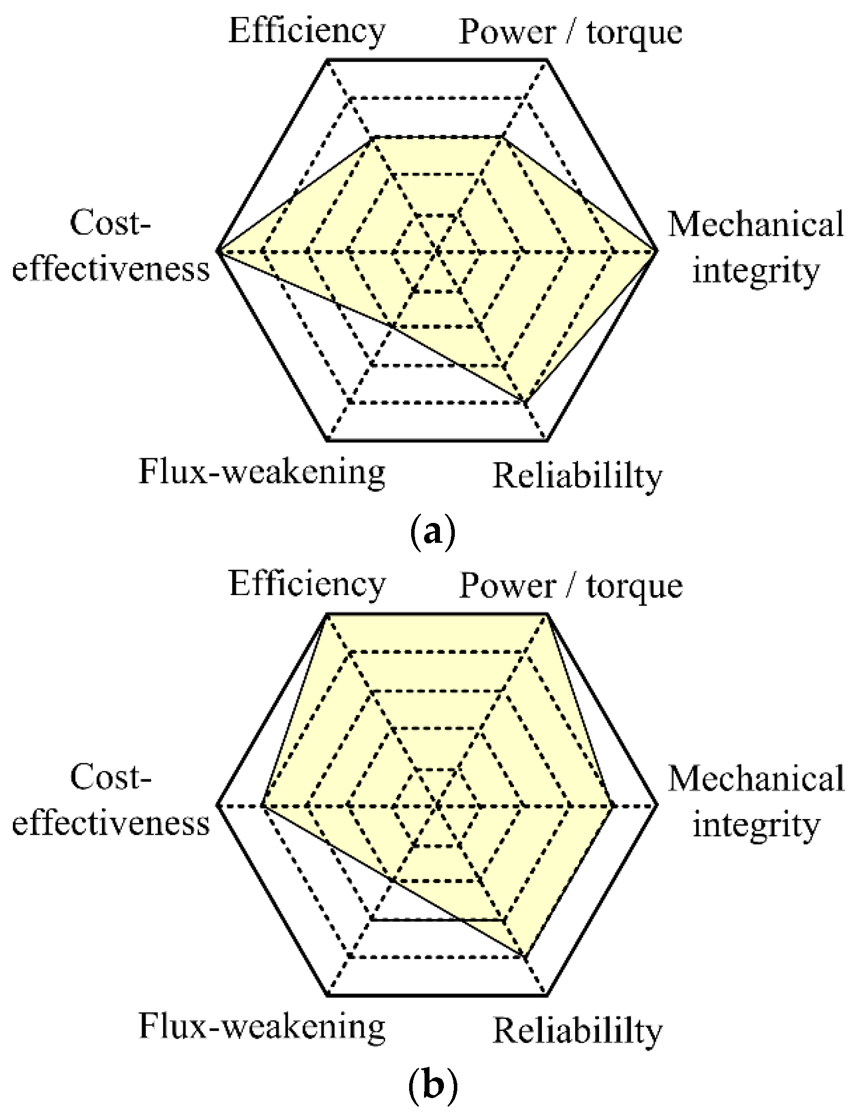
To evaluate all four proposed machines more effectively, a scoring index is adopted in
Figure 9. The scoring index consists of six important criteria while each of them is scored from point 1 to 5, where 1 implies the worst and 5 the best. Consequently, if all the criteria are included, the hybrid PS-SFDE machine will be able to serve as a very all-round machine for HEV industries.
7. Conclusions
In this paper, three PS machines, namely the PS-SFPM machine, the FA-PS-SFPM machine, and the PS-SFDE machine have been analyzed and compared based on key criteria. Unlike the previous design that allocates its DC-field winding to share spaces with PM materials, the proposed PS-SFDE machine instead installs two windings together. Upon the proposed arrangement, the PS-SFDE machine can improve its inherited demerits and hence exhibits excellent performances in various aspects. To be specific, the proposed PS-SFDE machine purposely maintains substantial PM material for excitation, such that it can provide adequate power and torque densities for HEV applications. After considering all major factors, the PS-SFDE machine has illustrated good potential for the HEV industry.
Author Contributions
The work presented in this paper is the output of the research projects undertaken by C.H.T.L. In particular, C.H.T.L. developed the topic, designed the system, analyzed the results, and wrote the paper. K.T.C., C.C.C. and T.W.C. helped provide guidance for improving the paper.
Funding
This work was supported by Croucher Foundation, Hong Kong Special Administrative Region, China.
Conflicts of Interest
The authors declare no conflict of interest.
References
- Chau, K.T.; Chan, C.C. Emerging energy-efficient technologies for hybrid electric vehicles. Proc. IEEE 2007, 95, 821–835. [Google Scholar] [CrossRef]
- Emadi, A.; Lee, Y.J.; Rajashekara, K. Power electronics and motor drives in electric, hybrid electric; plug-in hybrid electric vehicles. IEEE Trans. Ind. Electron. 2008, 55, 2237–2245. [Google Scholar] [CrossRef]
- Saber, A.Y.; Venayagamoorthy, G.K. Plug-in vehicles and renewable energy sources for cost and emission reductions. IEEE Trans. Ind. Electron. 2011, 58, 1229–1238. [Google Scholar] [CrossRef]
- Lee, C.H.T.; Chau, K.T.; Liu, C. Design and analysis of an electronic-geared magnetless machine for electric vehicles. IEEE Trans. Ind. Electron. 2016, 63, 6705–6714. [Google Scholar] [CrossRef]
- Zhu, Z.Q.; Howe, D. Electrical machines and drives for electric, hybrid; fuel cell vehicles. Proc. IEEE 2007, 95, 746–765. [Google Scholar] [CrossRef]
- Chau, K.T.; Chan, C.C.; Liu, C. Overview of permanent-magnet brushless drives for electric and hybrid electric vehicles. IEEE Trans. Ind. Electron. 2008, 55, 2246–2257. [Google Scholar] [CrossRef] [Green Version]
- Cheng, M.; Hua, W.; Zhang, J.; Zhao, W. Overview of stator-permanent magnet brushless machines. IEEE Trans. Ind. Electron. 2011, 58, 5087–5101. [Google Scholar] [CrossRef]
- Lee, C.H.T.; Chau, K.T.; Cao, L.B. Development of reliable gearless motors for electric vehicles. IEEE Trans. Magn. 2017, 53, 6500308. [Google Scholar] [CrossRef]
- Yang, Z.; Shang, F.; Brown, I.P.; Krishanmurthy, M. Comparative study of interior permanent magnet, induction; switched reluctance motor drives for EV and HEV applications. IEEE Trans. Transport. Electr. 2015, 1, 245–254. [Google Scholar] [CrossRef]
- Wang, T.; Zheng, P.; Zhang, Q.; Cheng, S. Design characteristics of the induction motor used for hybrid electric vehicle. IEEE Trans. Magn. 2005, 41, 505–508. [Google Scholar] [CrossRef]
- Wang, S.; Zhan, Q.; Ma, Z.; Zhou, L. Implementation of a 50-kW four-phase switched reluctance motor drive system for hybrid electric vehicle. IEEE Trans. Magn. 2005, 41, 501–504. [Google Scholar] [CrossRef]
- Wang, A.; Jia, Y.; Soong, W.L. Comparison of five topologies for an interior permanent-magnet machine for a hybrid electric vehicle. IEEE Trans. Magn. 2011, 47, 3606–3609. [Google Scholar] [CrossRef]
- Chen, J.T.; Zhu, Z.Q. Winding configurations and optimal stator and rotor pole combination of flux-switching PM brushless AC machines. IEEE Trans. Energy Convers. 2010, 25, 293–302. [Google Scholar] [CrossRef]
- Cao, R.; Mi, C.; Cheng, M. Quantitative comparison of flux-switching permanent-magnet motors with interior permanent magnet motor for EV, HEV; PHEV applications. IEEE Trans. Magn. 2012, 48, 2374–2384. [Google Scholar] [CrossRef]
- Deodhar, R.P.; Pride, A.; Iwasaki, S.; Bremner, J.J. Performance improvement in flux-switching PM machines using flux diverters. IEEE Trans. Ind. Appl. 2014, 50, 937–978. [Google Scholar] [CrossRef]
- Evans, D.J.; Zhu, Z.Q. Novel partitioned stator switched flux permanent magnet machines. IEEE Trans. Magn. 2015, 51, 8100114. [Google Scholar] [CrossRef]
- Zhu, Z.Q.; Al-Ani, M.M.J.; Liu, X.; Lee, B. A mechanical flux weakening method for switched flux permanent magnet machines. IEEE Trans. Energy Convers. 2015, 30, 806–815. [Google Scholar] [CrossRef]
- Lee, C.H.T.; Kirtley, J.L.; Angle, M.; Nian, H. Quantitative comparison of partitioned-stator machines for hybrid electric vehicles. CES Trans. Electr. Mach. Syst. 2017, 1, 146–153. [Google Scholar]
- Lee, C.H.T.; Kirtley, J.L.; Angle, M. A partitioned-stator flux-switching permanent-magnet machine with mechanical flux adjusters for hybrid electric vehicles. IEEE Trans. Magn. 2017, 53, 3000807. [Google Scholar] [CrossRef]
- Amara, Y.; Vido, L.; Gabsi, M.; Hoang, E.; Ahmed, A.H.B.; Lecrivain, M. Hybrid excitation synchronous machines: Energy-efficient solution for vehicles propulsion. IEEE Trans. Veh. Technol. 2009, 58, 2137–2149. [Google Scholar] [CrossRef]
- Hau, W.; Yin, X.; Zhang, G.; Cheng, M. Analysis of two novel five-phase hybrid-excitation flux-switching machines for electric vehicles. IEEE Trans. Magn. 2014, 50, 8700305. [Google Scholar]
- Hua, H.; Zhu, Z.Q. Novel hybrid-excited switched-flux machine having separate field winding stator. IEEE Trans. Magn. 2016, 52, 8104004. [Google Scholar] [CrossRef]
- Liu, C.; Chau, K.T. Electromagnetic design and analysis of double-rotor flux-modulated permanent-magnet machines. Prog. Electromagn. Res. 2012, 131, 81–97. [Google Scholar] [CrossRef]
- Lee, C.H.T.; Chau, K.T.; Liu, C.; Chan, C.C. Overview of magnetless brushless machines. IET Electr. Power Appl. 2017, 12, 1117–1125. [Google Scholar] [CrossRef]
© 2018 by the authors. Licensee MDPI, Basel, Switzerland. This article is an open access article distributed under the terms and conditions of the Creative Commons Attribution (CC BY) license (http://creativecommons.org/licenses/by/4.0/).


