

Design and Aerodynamic Characteristics Analysis of an Electric Racecar Body Based on CFD

Department of Mechatonics Engineering, Foshan University, Foshan 528000, China
*
Author to whom correspondence should be addressed.
World Electr. Veh. J. 2024, 15(5), 192; https://doi.org/10.3390/wevj15050192
Submission received: 16 January 2024
/
Revised: 22 April 2024
/
Accepted: 27 April 2024
/
Published: 29 April 2024
(This article belongs to the Topic Advanced Electrical Machine Design and Optimization Ⅱ)
Abstract
:This study focuses on the development of a body for an electric racecar, utilizing CAD software for the design. A simplified full-vehicle geometric model was constructed. Based on fundamental theories of computational fluid dynamics and using CAE software platforms, the shear stress transport (SST) k-ω physical model was chosen to establish a three-dimensional computational model of the racecar’s external flow field. Simulations were conducted to analyze the pressure, airflow streamlines, and velocity distribution around the body and its surrounding flow field, elucidating the impact of body shape structure on aerodynamic characteristics. Finally, a manufacturing process for the body was designed, and a prototype was produced and integrated into the complete vehicle for road testing. The results indicate that the designed electric racecar body maintained consistent airflow over its surface, meeting the basic requirements of aerodynamics.
1. Introduction
The Formula Electric Vehicle Competition is an event in which teams of students from higher education institutions, majoring in automotive engineering or related fields, design and manufacture electric vehicles. In accordance with the competition rules and car manufacturing standards, the participating teams design and manufacture, within one year, a small single-seater leisure car with excellent performance in acceleration, braking, handling, safety and energy consumption, and that is able to complete the competition link required by the rules [1]. The aerodynamic characteristics of the electric racecar body significantly affect the vehicle’s power performance and handling stability [2].
This article analyzes and studies the development of the electric racecar body for the car produced by entrants from Foshan University. The literature [3,4,5,6,7] mentions a numerical simulation of the external flow field of the racecar body, but only provides simple analyses of the external flow field of the car body or the installation of an air kit, etc., which does not further integrate the simplified model of the whole car. In the exploration of styling and aerodynamic performance, there is no processing and road test evaluation of the car body model after simulation analysis. In view of this, this article uses engineering software to design an aerodynamic body and analyzes the aerodynamic characteristics of the racecar. Finally, the design model makes use of carbon fiber vacuum processing technology to produce the actual body, and the assembly is integrated into the whole car. An outdoor road test further verified the aerodynamic characteristics of the car body.
2. Theoretical Basis and Control Equations
2.1. Theoretical Basis of Racecar Aerodynamics
In conditions such as high-speed driving and turning, the aerodynamic forces and moments on an electric racecar are primarily determined by the driving speed, the shape of the car body, and the yaw angle. The aerodynamic forces acting on the racecar can be divided into aerodynamic drag, aerodynamic lift, and aerodynamic lateral force [8].
The aerodynamic drag Fd is as follows:
The aerodynamic lift F1 is as follows:
The aerodynamic lateral force Fy is as follows:
In these formulas, A is the windward area, V is the vehicle speed, ρ is the air density, and Cd, C1, and Cy are the drag coefficient, lift coefficient and lateral force coefficient, respectively.
2.2. Control Equation for Numerical Simulation
Based on the basic theory of aerodynamics, assuming a maximum speed of the racecar of 120 km/h and using the theory that the Mach number is less than 0.3, the flow is considered incompressible. According to the Reynolds theory, the flow is turbulent, and the disturbed airflow is governed by the laws of physical conservation, including the conservation of mass, momentum, and energy [9].
The continuity equation is as follows:
where is the velocity vector, is the fluid density, and is the time. For incompressible fluids, the density typically does not change with time.
The momentum conservation equation is as follows:
The energy conservation equation is as follows:
where vi is the speed, T is the temperature, k is the thermal conductivity of the fluid, CP is the specific heat capacity of the fluid, and ST represents the internal heat source and the part of the mechanical energy of the fluid that is converted into thermal energy due to viscous effects, i.e., the viscous dissipation term [10].
3. Design of the Electric Racecar Body
3.1. Design Method of Aerodynamic Characteristics and Rule Requirements on the Car Body
Traditional car body design generally requires a full-scale clay model to be tested in a wind tunnel, with improvements made based on the results of these tests. This method requires a significant investment of human, material, and financial resources [11]. However, the development of CAD/CAE/CAM and computational fluid dynamics (CFD) has turned simulation technology into a major technique in the design of electric racecar bodies due to its low cost, high precision, and the ability to visually represent post-processing effects [12]. The design process of an electric racecar based on CFD is illustrated in Figure 1.
The car body provides the driver with a good driving environment, offering both excellent aerodynamic performance and protection for the driver while also serving a decorative function for the racecar. A stylish and dynamic car body enhances the car’s sportiness, and the competitiveness of the racecar is supported by its functional body. The Formula Student Rulebook specifies that the car must have exposed wheels and an open cockpit, and that the four wheels cannot be aligned in a straight line, as shown in Figure 2. Apart from the cockpit opening, no part of the body is allowed to intrude into the space from the front end of the car to the main roll hoop. Small openings are permitted in the area of the front suspension components. The wheelbase of the car must be at least 1525 mm, with the narrower track width being at least 75% of the wider track width.
3.2. Principles for Body Selection and Overall Scheme Determination
Body types generally fall into two main categories: one is a shuttle-like shape with wheels outside, and the other resembles natural biological forms or is water drop-shaped, with wheels that are more enclosed. Shuttle-like body designs are less complex to design and generally have a wider track width for good stability; however, the body is too narrow overall, leading to poor driving control, overly long wheel support beams, and lower overall stiffness. On the other hand, external forms found in nature, such as dolphins and whales, not only meet aesthetic requirements but also favor aerodynamic efficiency due to their streamlined shapes [13]. Among these, the water drop shape has the lowest drag coefficient known to date [14], a result that is shown in Table 1, which compares the approximate drag coefficients of various shapes [15]. Water-drop-shaped bodies can avoid the problems associated with the first category of bodies, but designing a water drop shape is more challenging. Therefore, the design of electric racecar bodies mainly imitates biological forms found in nature.
The body is one of the four major assemblies of the racecar and its development must follow the overall V-shaped development procedure of the whole vehicle shown in Figure 3 [16]. Therefore, when determining the design priorities of the entire vehicle, the priorities of the body and chassis systems must be considered. Due to insufficient accumulation of basic data on the team’s car body and its own conditions, to prevent dimensional interference between the chassis and body systems, it has been determined that the chassis should be prioritized, and that the body should therefore provide as much design space for the chassis as possible. That is, at the initial stage of the design, one should coordinate and determine the size range of the chassis components, such as the frame, wheels, brakes, and steering, in conjunction with the size requirements specified in the rulebook, in order to determine the basic dimensions of the chassis. Then, one should establish the initial geometric model of the chassis as shown in Figure 4, before finally designing the body based on the dimensions of the chassis model.
3.3. Body Shape Design and Geometric Modeling
The design and geometric modeling of the car body primarily fall into three categories: open, semi-enclosed, and fully enclosed. For Formula racing competitions, experience from numerous energy-saving races and data analysis suggest that a semi-enclosed car body, combined with the selected natural biological forms, not only meets the regulatory requirements for racecar bodies but also effectively reduces drag, thereby lowering fuel consumption. Therefore, the designers of the car body opted for a semi-enclosed structure paired with biomimetic shapes. This approach not only satisfies aesthetic preferences but also leverages streamlined biological forms for energy efficiency [17].
Human–machine engineering for electric racecars is crucial. In competitions, the driver is a key factor in determining race outcomes, and the ability of the driver to fully exploit the car’s performance hinges on comfortable driving conditions. This necessitates the design of the car’s ergonomics to meet race regulations. Good ergonomic design in racecar bodies should at least ensure [18]: (1) a comfortable seating position for the driver; (2) clear visibility for the driver to ensure safety; and (3) ample space in the cockpit to prevent interference with the driver’s operations.
Taking into account the competition requirements and considering the overall layout of the chassis, power system, ignition system, batteries, brakes, steering, and other modules, alongside the basic chassis dimensions determined in Figure 4 and previous base parameters of the racecar body, the car body’s three-dimensional geometric model is developed using the Catia software’s shape design module, Imagine and Shape. Initially, the front part of the body is drawn and smoothed in order to ensure a seamless transition, as shown in Figure 5. The arc at the bottom front is enlarged to increase airflow speed across this area. The sides of the driver’s cockpit are then designed based on the frame specifications and the positions in which the driver supports themselves when entering and exiting the seat. The rear half of the body covers components such as the engine, and the design of the rear cover aids in rainproof checks during inspections. The initial geometric shape of the designed body, arrived at after comprehensive consideration, is shown in Figure 6.
4. Simulation Analysis
4.1. Model Simplification
To facilitate the analysis and calculation process and improve the overall mesh quality, the three-dimensional model of the racecar was simplified in four aspects based on the following simulation requirements: (1) the removal of components such as the front and rear suspension arms, steering rods, and main hoop that cause minimal disturbance to the flow field; (2) the addition of a driver model, with the cylindrical position representing the driver’s head when seated in the cockpit, and the spherical size similar to that of a driver’s helmet; (3) the simplification of the powertrain compartment and transmission gear compartment into a single box-shaped structure, sized according to the dimensions of the rear part of the frame; and (4) the simplification of the tires into cylindrical shapes, sized according to the actual tire dimensions, and the creation of a raised platform at the point of contact with the ground to simulate tire deformation and improve mesh quality at the interface between the tire and ground [19]. The simplified models are shown in Figure 7 and Figure 8.
4.2. Computational Domain and Meshing
For the car body model, a sufficiently large rectangular computational domain is used to simulate the space flow field area, with the domain’s inlet distance being 2–3 times the car length from the front, and the outlet distance being 7–8 times the car length from the rear. The distance to the side walls is about 3–4 times the car width, and the height is about 3–4 times the car height [20]. The size of the computational area for the CFD simulation wind tunnel test is as shown in Table 2, and the created computational fluid domain is shown in Figure 9. A mesh refinement zone is created around the car body and in the turbulent area at the rear of the car, as shown in the boxed area in Figure 10. Outside of the refinement zone, a T-Glib mesh growth strategy is set, allowing the small-size meshes at the edge of the refinement zone to rapidly grow into a large-size meshes, filling the entire computational domain.
The quick method is used first to generate shell/surface meshes, and then volume meshes are generated based on this [21]. The final mesh consists of approximately 2.73 million volume mesh elements. The symmetry plane mesh of the car body is shown in Figure 11, and Figure 12 displays the mesh in the car body’s refinement zone, clearly illustrating the mesh situation in the refinement area.
4.3. Simulation Solution Setup and Analysis
The simulation solution process mainly includes setting up the solver, selecting the turbulence model, setting the boundary conditions, and performing computer iterations.
(1) Solver Setup: The mesh divided by preprocessing tools is imported into post processing solver for solver setup. The turbulence model is initially defined; given the low Reynolds number of the simulation model, the Reynolds-averaged Navier–Stokes (RANS) corrected SST k-ω model is chosen. Boundary conditions are defined as follows: the inlet boundary is a velocity inlet, with a velocity value of 15 m/s and a turbulence intensity of 5%; the outlet boundary is a pressure outlet, with a pressure value at standard atmospheric pressure and a turbulence intensity of 5%. The boundary around the computational domain and the ground boundary are set as slip walls, with a velocity of 15 m/s in the direction of airflow. The wheel surface uses a rotating wall, with the rotation center at the wheel center, and the linear speed matching the vehicle speed, while the rotation speed is determined based on the vehicle speed [22]. Second-order upwind discretization is used for the momentum and component equations.
(2) Analysis: After 2000 steps of iterative calculation, the simulation results were obtained. From the velocity contour (Figure 13), it can be seen that the velocity in the front part of the racecar is 15 m/s in the green-blue areas, changing to yellow above and in front of the driver and indicating speeds of 18 m/s, while the blue area at the rear of the car indicates airspeeds lower than 5 m/s. The pressure contour (Figure 14) shows the dark blue area at the front of the car and in front of the driver, indicating the highest pressure, and the cyan-blue area at the rear of the driver and the bottom front part of the car, which indicates higher pressure. This means that the areas directly facing the wind, such as the front of the car, the driver’s face, and the tires, experience a high positive pressure gradient.
Figure 15 represents the air flow vectors, where the arrows indicate the direction of air movement. The speed and direction of the air change at different locations, with the flow direction and concentration under and above the car surface varying according to the shape of the car body. In the central blue region of the car, the speed is lower and the flow is denser, while behind the car, the speed decreases and the flow becomes sparser. Figure 16 shows the airflow streamlines; a red area next to the driver indicates the highest airspeed location, possibly because this part is not streamlined and the vertical plane directly collides with the air, creating significant resistance. The streamlined design at the front end of the car body reduces drag and ensures even pressure distribution across the body. The blue area at the rear of the car has the lowest airflow speed, but due to airflow separation at the wheel parts, this area becomes a negative pressure zone, leading to vortex formation, rotation, and detachment, consuming a significant amount of energy and increasing aerodynamic drag [23,24,25,26].
Figure 17, Figure 18 and Figure 19 present multi-scenario combined simulations, with the results clearly demonstrating complex flow phenomena resulting from the influence of the racecar body, rear wing, and other components. The body of the racecar, as well as the front and rear wings, are significantly affected by aerodynamic loads. Analysis based on the combined scenario simulations of pressure contours, velocity vectors, and airflow streamlines indicates that the car body achieves the desired aerodynamic design characteristics.
Finally, the aerodynamic drag and lift calculated in the simulation are compared with the data from the previous generation of the car body. As shown in Table 3, the comparison between the aerodynamic drag and lift data of the previous racecar body and the new design reveals that the new design reduces the drag by 13 N and decreases the aerodynamic lift by 3.6 N. This improvement in the car body’s aerodynamic performance, despite a slight enhancement in lift compared with the previous generation, demonstrates that a streamlined body design can enhance aerodynamic efficiency.
5. Manufacturing of the Racecar Body
5.1. Making of the Body Mold
First, points are marked along the longitudinal direction on the car body geometric model at specified intervals. Then, cross-sections are taken at each point and printed at a 1:1 scale. The prepared foam is then cut into the geometric shapes of these cross-sections. These foam sections are stacked in the order they were marked, with each layer of foam sections closely bonded together using epoxy resin, forming the preliminary shape of the car body. Next, the foam is sanded down to a shape that closely matches the design model, as shown in Figure 20, resulting in the sanded foam mold.
After that, clay is applied to the mold, and once the clay mold has dried, a scraper is used to smooth its surface. After the mold has been smoothed, a release agent is sprayed on it. Once the release agent has completely dried, two to three layers of mold release wax are applied. The mold release wax needs to be evenly applied, especially at the edges and corners, which requires multiple applications.
5.2. Manufacturing of the Car Body Shell
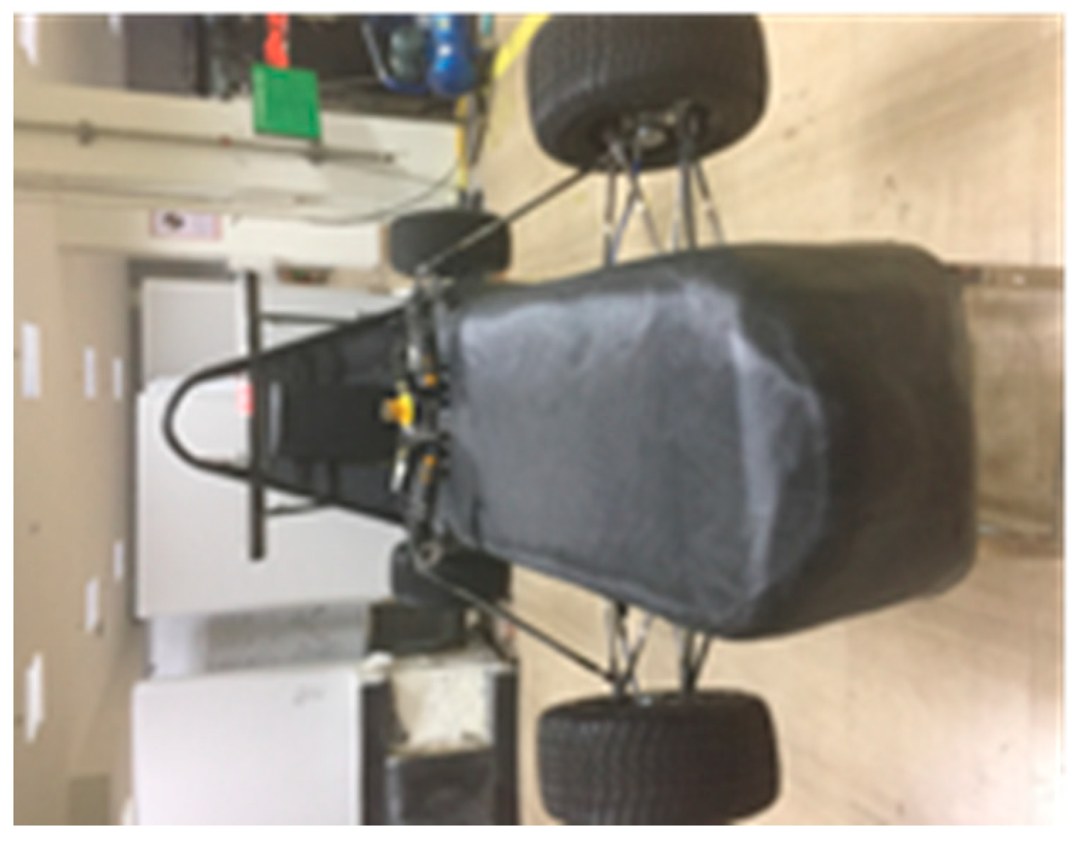
First, the prepared carbon fiber cloth is attached to the surface of the mold, and epoxy resin, mixed in a specified ratio, is applied over the mold. Following the competition’s hardness rules, either two or three layers of carbon fiber cloth may be chosen, after which a mixture of resin and glue, the ratio of which is a respective 3:1, is used to cure the carbon fiber cloth. Then, a vacuum is used to smooth the surface, and the cured car body is as shown in Figure 21. After curing, the body is demolded and then mounted onto the frame. After sanding, the body is completed. Figure 22 shows the finished product and its integration with the electric racecar’s body.
The electric racecar participated in the Formula racing competition held at the racetrack. After the competition, the car was returned to the school’s automotive laboratory, where the disassembled car body was inspected. No significant deformation or cracking was found and the driver drove the car smoothly to complete the race. The driver also gave subjective evaluations of aerodynamic characteristics, indicating that the designed electric racecar body meets the basic aerodynamic performance requirements.
6. Conclusions and Discussion
In racecar design, the structure of the body significantly impacts the vehicle’s dynamic performance. This article has explored the aerodynamic characteristics of the car body through the establishment of CFD models, numerical simulation analysis, and physical experiments on actual vehicles. The conclusions of this study are as follows:
(1) Based on the analysis of the fundamental theories of electric race aerodynamics, in accordance with competition rules, and incorporating aesthetic requirements, the basic geometric structure model of the car body was designed.
(2) A finite element model for the analysis of the electric racecar’s aerodynamic characteristics was established, and CFD technology was used to conduct simulation analysis. This provided pressure, airflow streamlines, and velocity distribution around the car body and its flow field, offering a theoretical reference for the final design of the car body.
(3) The car body’s manufacturing process was analyzed and designed, and physical prototypes were made and integrated into the racecar. Physical experiments on the complete vehicle demonstrated that the designed electric racecar body meets the basic requirements of aerodynamics.
(4) The design of the car body’s streamline affects the drag encountered by the electric racecar during operation. To enhance the aesthetic design of the car body, the lines of the body must be based on aerodynamic characteristics. The results show that the optimized car body’s aerodynamic drag is reduced to 30.5 N, a reduction of 13 N from the previous generation, and the aerodynamic lift is reduced to 20.5 N, a decrease of 3.6 N. Therefore, the aerodynamic performance of the car body has been improved, and the overall safety performance of the vehicle has also been enhanced.
There are two points of discussion:
(1) The study focuses only on the car body and does not extend to the design optimization of other components that could improve aerodynamic performance. The experimental data are derived from virtual simulations. All other factors that might affect aerodynamic performance are considered ideal. Certain manufacturing issues, such as dimensional errors, surface smoothness, and curvature precision, can occur in the car body manufacturing process, introducing some errors in the analysis and calculation.
(2) When dividing the mesh, too many meshes could lead to insufficient computer memory and program crashes. Conversely, too few meshes might result in inaccurate calculation results. Therefore, it is necessary to refer to the accumulated data from other racing teams and set experienced values for mesh division in order to improve its efficiency and accuracy.
Author Contributions
Conceptualization, J.L. and L.W.; methodology, F.L.; software, J.L.; validation, J.L., F.L. and L.W.; formal analysis, J.L.; investigation, J.L.; resources, J.L.; data curation, L.W.; writing—original draft preparation, J.L.; writing—review and editing, J.L.; visualization, J.L.; supervision, J.L.; project administration, J.L.; funding acquisition, J.L. All authors have read and agreed to the published version of the manuscript.
Funding
This research was funded by the Guangdong Basic and Applied Basic Research Foundation (No. 2020A 1515110999).
Data Availability Statement
The original contributions presented in the study are included in the article, further inquiries can be directed to the corresponding author.
Conflicts of Interest
The authors declare no conflict of interest.
References
- China University Formula Automobile Race Rules Committee. The Third Edition of the Rules of the 2019 Chinese University Formula Competition; Automobile Engineering Society: Beijing, China, 2019. [Google Scholar]
- Xuan, Z.; Han, Z.H.; Zheng, F.Y.; Li, G. Design and Analysis of Aerodynamic Devices On FSC Racing Car. J. Liaoning Univ. Technol. 2015, 35, 308–312. [Google Scholar]
- Cheng, X.H.; Luo, S.M.; Chang, X.F.; Xie, D. Numerical Analysis of an External Flow-Field a-round a Formula SAE Car Body Based on FLUENT. Adv. Mater. Res. 2014, 1039, 17–24. [Google Scholar] [CrossRef]
- Lu, X. Research on the Flow Field Around a Formula SAE Car; Sae Technical Papers; Society of Automotive Engineers (SAE): Warrendale, PA, USA, 2015. [Google Scholar]
- Bai, Q.Y.; Wang, H.; Li, J.F.; Hao, X.F. Combinational design and analysis of aerodynamic devices of FSAE racing car. J. Hefei Univ. Technol. 2016, 39, 592–597. [Google Scholar]
- Yang, W.; Xie, R.X.; Cao, Z.H.; Meng, Y.J. Improving the Aerodynamic Package for a Formula SAE Race Car. J. China Sci. Pap. 2018, 13, 2050–2054. [Google Scholar]
- Yan, Z.Y.; Du, C.Q.; Hu, Y.F.; Wang, J.P. Study on aerodynamic performance of rear wing for Formula SAE racing cars based on finite element method. J. Chongqing Univ. 2019, 42, 29–39. [Google Scholar]
- Chao, Z.Y. Automotive Aerodynamics Simulation Technology; Peking University Press: Beijing, China, 2011; pp. 47–67. [Google Scholar]
- Nan, Q.; Ying, B.S.; Wu, J.J.; Yao, J.Y. Effect Study of Rear Diffuser on Aerodynamic Characteristics of Formula SAE Racing Car. Mach. Des. Manuf. 2019, 10, 72–79. [Google Scholar]
- Zhai, G.; Ren, C.; Tong, W. Design and optimization of inner-rotation nozzle in negative pressure duster. Adv. Mech. Eng. 2019, 11. [Google Scholar] [CrossRef]
- Zhang, Q.; Zhao, Y.Q.; Yang, G.Q. Overview of the development of numerical simulation of automobile external flow field based on CFD. Agric. Equip. Veh. Eng. 2005, 12, 8–11. [Google Scholar]
- Zhang, F.J.; Yang, L.; Wan, T.T.; Zhong, X.H.; Li, J.C.; Qiu, L.W. Research of FSE racing Car Aerodynamics Devices Based on CFD. Agric. Equip. Veh. Eng. 2019, 57, 54–57. [Google Scholar]
- Guo, Y.; Zhang, X.; Li, X.L.; Chao, H.; Li, X. Optimization design of Honda energy-saving racing car body. Highw. Automob. Appl. 2013, 6, 17–19. [Google Scholar]
- Available online: https://www.sohu.com/a/301721217_739408 (accessed on 16 March 2019).
- Abdul Latif, M.F.; Hashim, M.N.; Rashid, M.Z.A.; Azhari, M.A.; Othman, M.N. Roof Box Shape Streamline Adpatation and the Impact towards Fuel Consumption, MATEC Web of Conferences. In Proceedings of the Engineering Technology International Conference 2016 (ETIC 2016), Ho Chi Minh City, Vietnam, 5–6 August 2016. [Google Scholar]
- Luo, Y.; Feng, Y. Automotive Design; Machinery Industry Press: Beijing, China, 2011. [Google Scholar]
- Li, J.; Wang, D.; Tian, Y.; Pan, H. Lightweight Design of Hona Energy-Saving Racing SINGLE-Shell Body based on Carbon Fiber Material. J. Phys. Conf. Ser. 2020, 1622, 012113. [Google Scholar] [CrossRef]
- Qiu, C.W.; Yang, L.; Li, J.C.; Zhong, X.H. Design and verification of monocoque body of FSE electric racing car. Agric. Equip. Veh. Eng. 2019, 57, 22–26. [Google Scholar]
- Han, X.Q.; Wang, H.Y.; Hou, W.B. Design and CFD analysis of aerodynamics kit based on FSAE racing car. Exp. Sci. Technol. 2016, 14, 3–7. [Google Scholar]
- Wu, J.; Zhong, Z.H.; Gu, Z.Q. Further research on numerical simulation of automobile external flow field. Chin. J. Mech. Eng. 2003, 39, 110–113. [Google Scholar]
- Tan, J.F. The basic mechanics of high-speed cornering of a Formula One car. Eng. Phys. 1994, 1, 15–16. [Google Scholar]
- Katz, J.; Plotkin, A. Low Speed Aerodynamics; University of Cambridge: Cambridge, UK, 2002. [Google Scholar]
- Fu, L.M. Numerical Calculation of Automobile Aerodynamics; Beijing Institute of Technology Press: Beijing, China, 2001. [Google Scholar]
- Zhang, H.H. CFD analysis and optimization of aerodynamic characteristics of a car. J. Shaanxi Univ. Sci. Technol. 2002, 2, 70–73. [Google Scholar]
- Wang, F.J. Computational Fluid Dynamics Analysis; Tsinghua University Press: Beijing, China, 2005; pp. 120–121. [Google Scholar]
- Wang, F.L. Numerical simulation study on the influence of crosswind on car aerodynamic characteristics. J. Harbin Inst. Technol. 2006, 8, 75–77. [Google Scholar]
Figure 1.
Body design process.

Figure 2.
Racing car requirements.
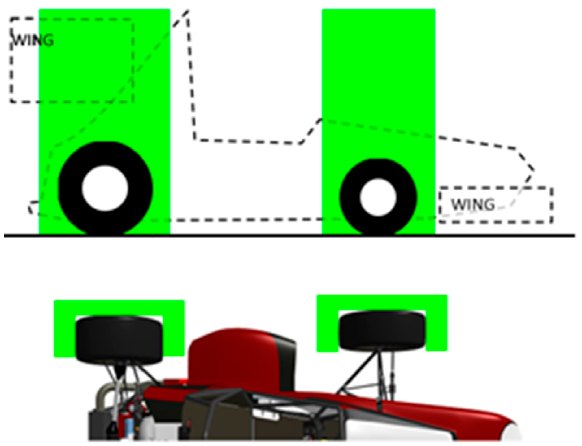
Figure 3.
The development program of the electric racecar.
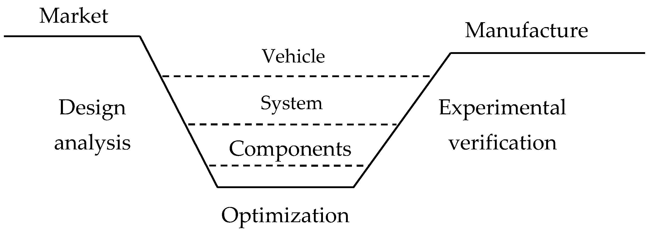
Figure 4.
Geometric model of the chassis.

Figure 5.
The front part of the car.
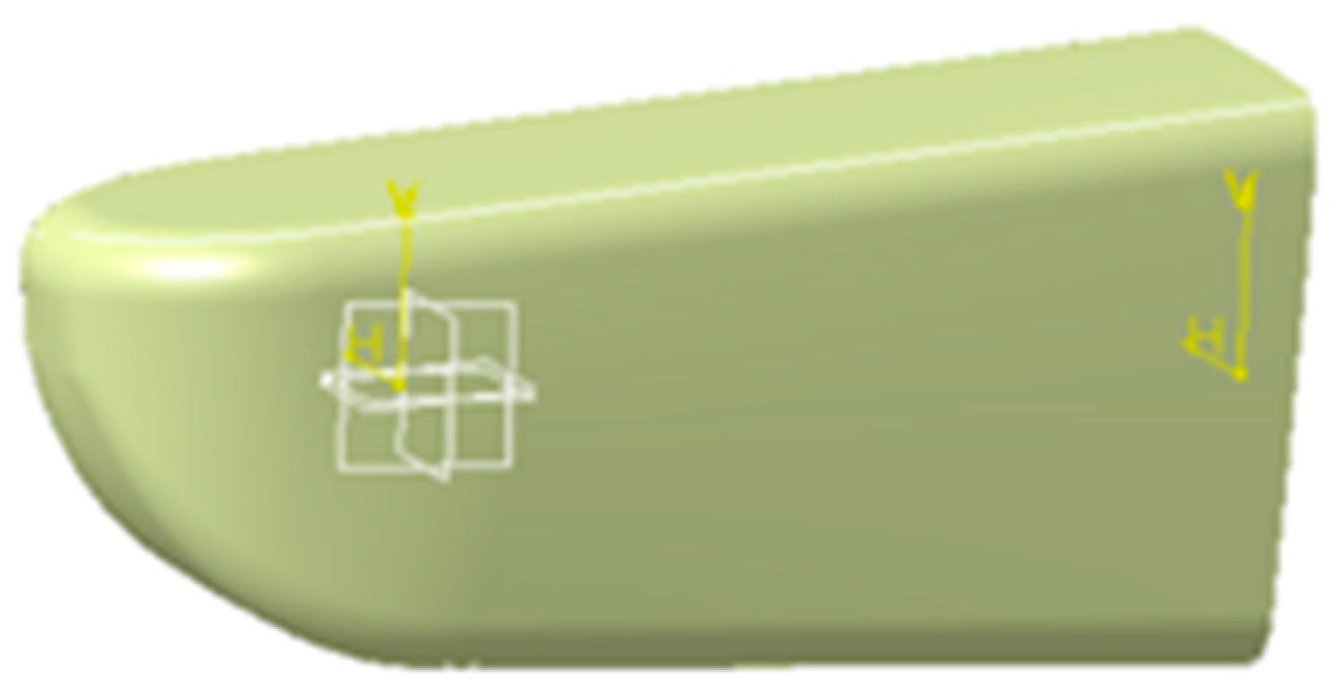
Figure 6.
Body.
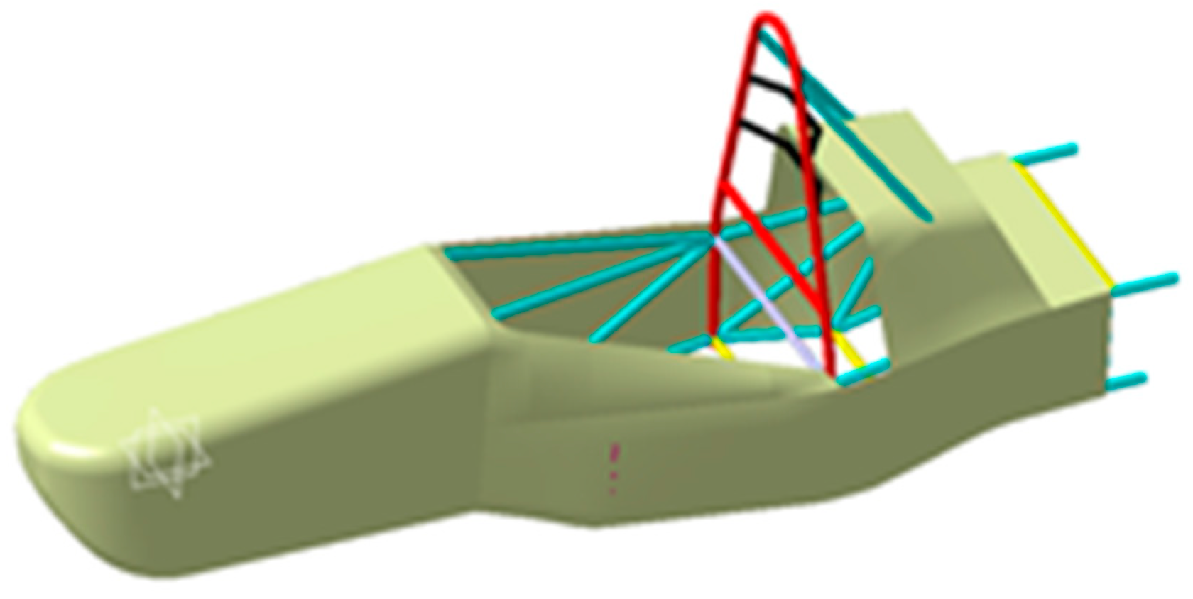
Figure 7.
Simplified body model.

Figure 8.
Simplified tire model.

Figure 9.
Fluid analysis calculation domain.
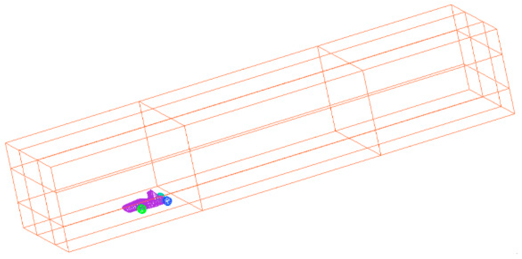
Figure 10.
Mesh refinement zone.
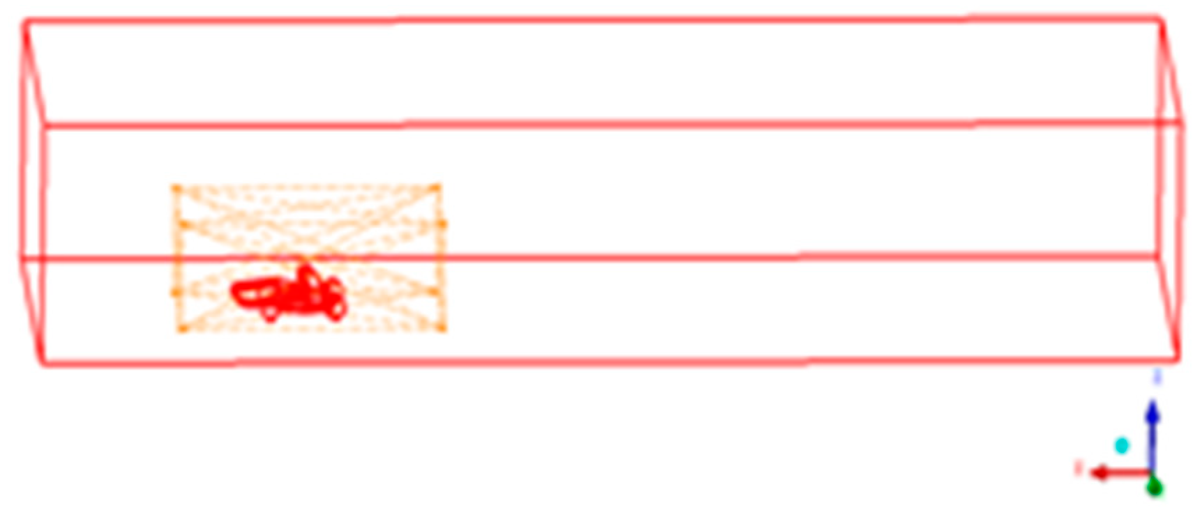
Figure 11.
Symmetry plane mesh distribution.
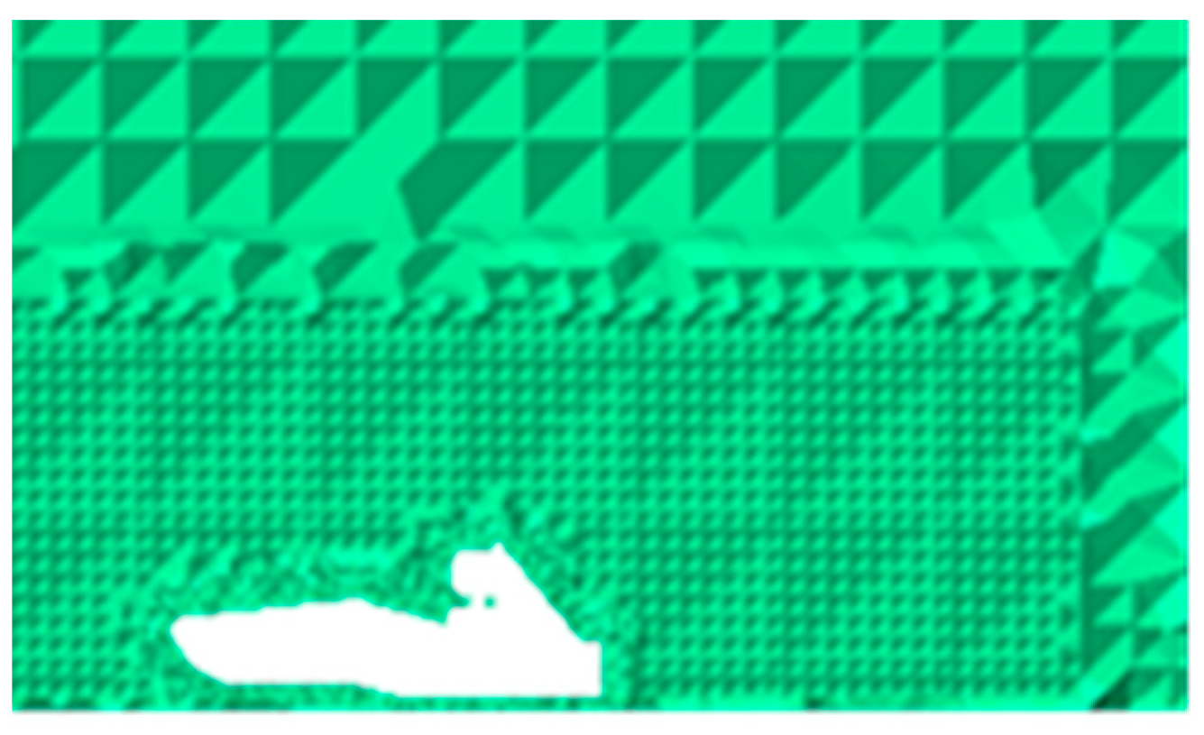
Figure 12.
Mesh distribution of densified area.

Figure 13.
Velocity Contour.
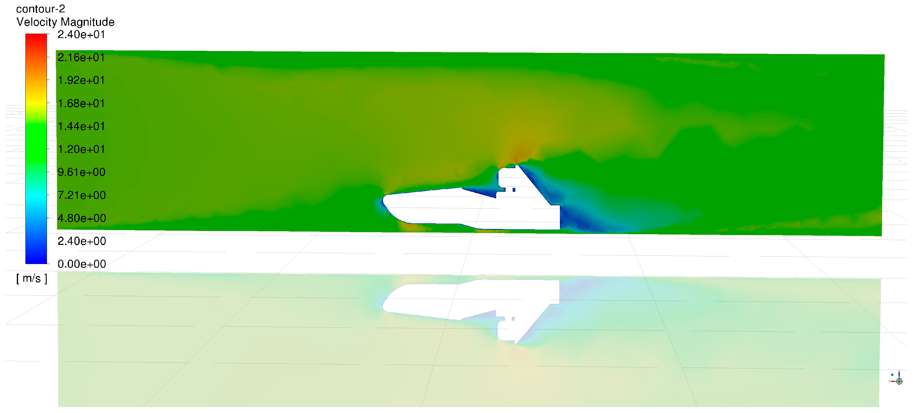
Figure 14.
Pressure contour.
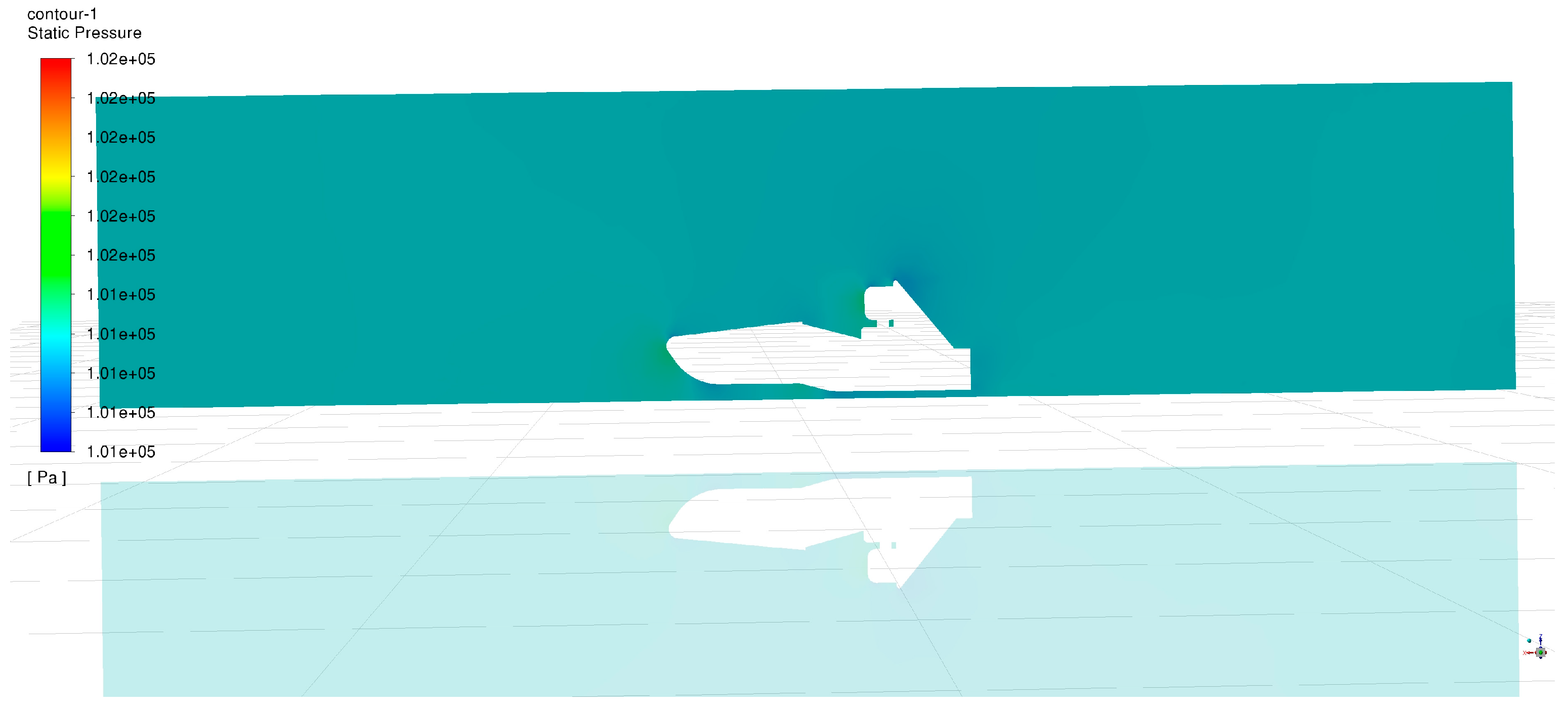
Figure 15.
Velocity vectors.

Figure 16.
Airflow streamlines.

Figure 17.
Pressure contours and airflow streamlines.
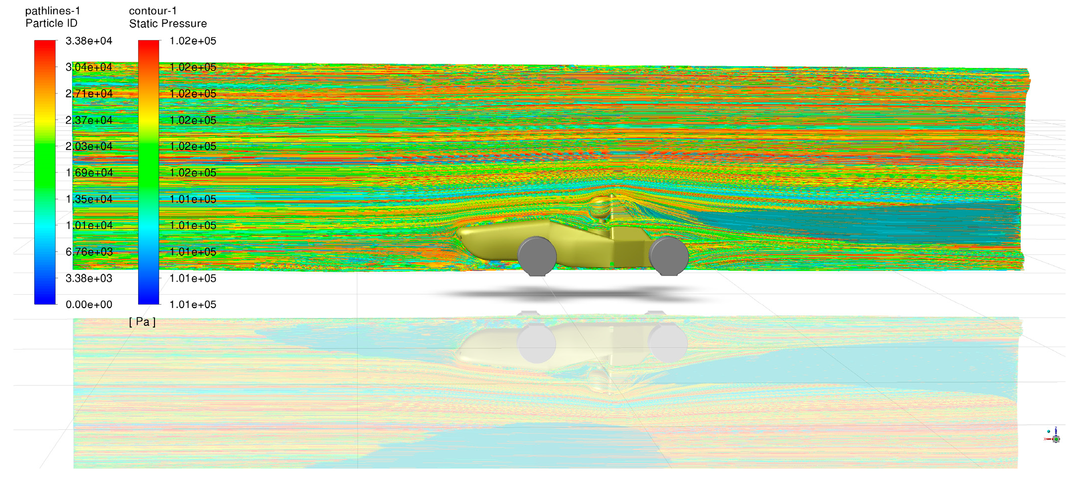
Figure 18.
Pressure and velocity vector.
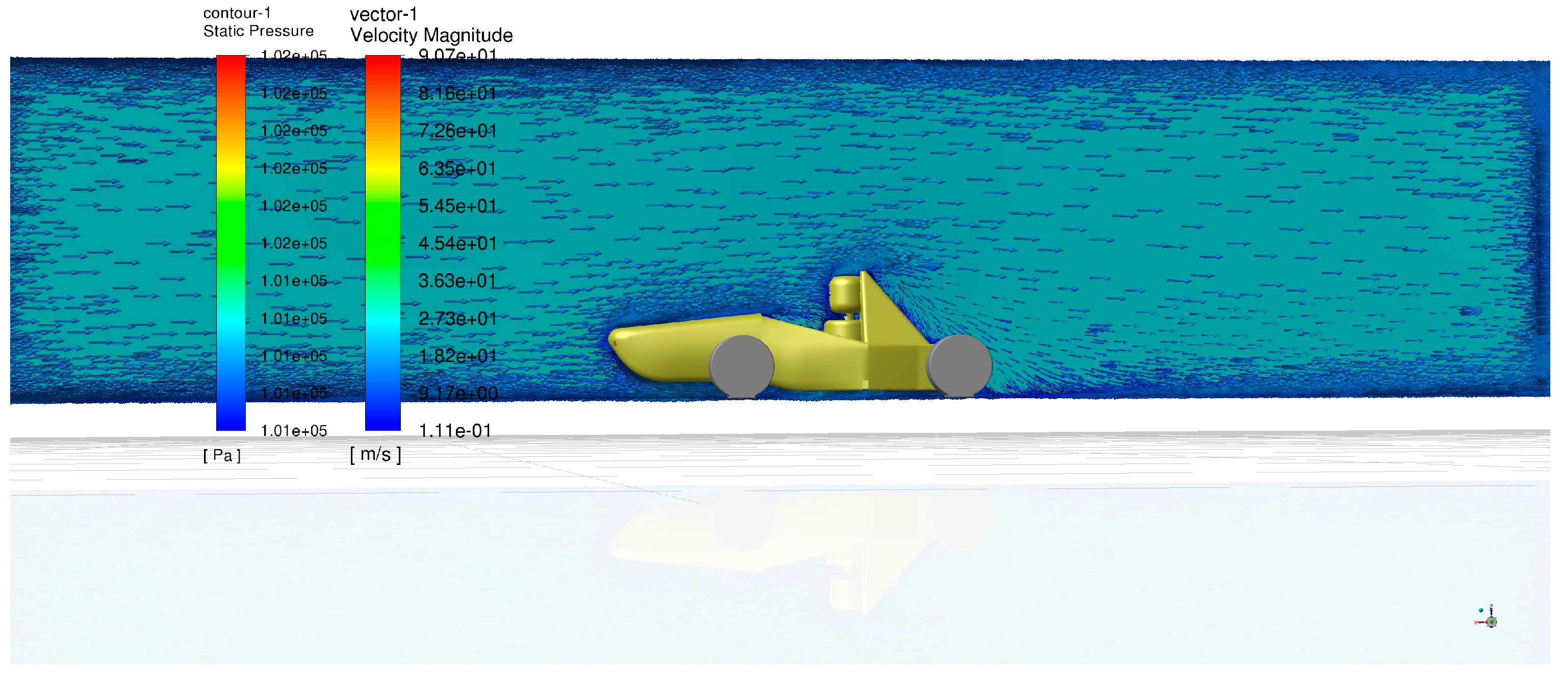
Figure 19.
Pressure, velocity and airflow streamline.
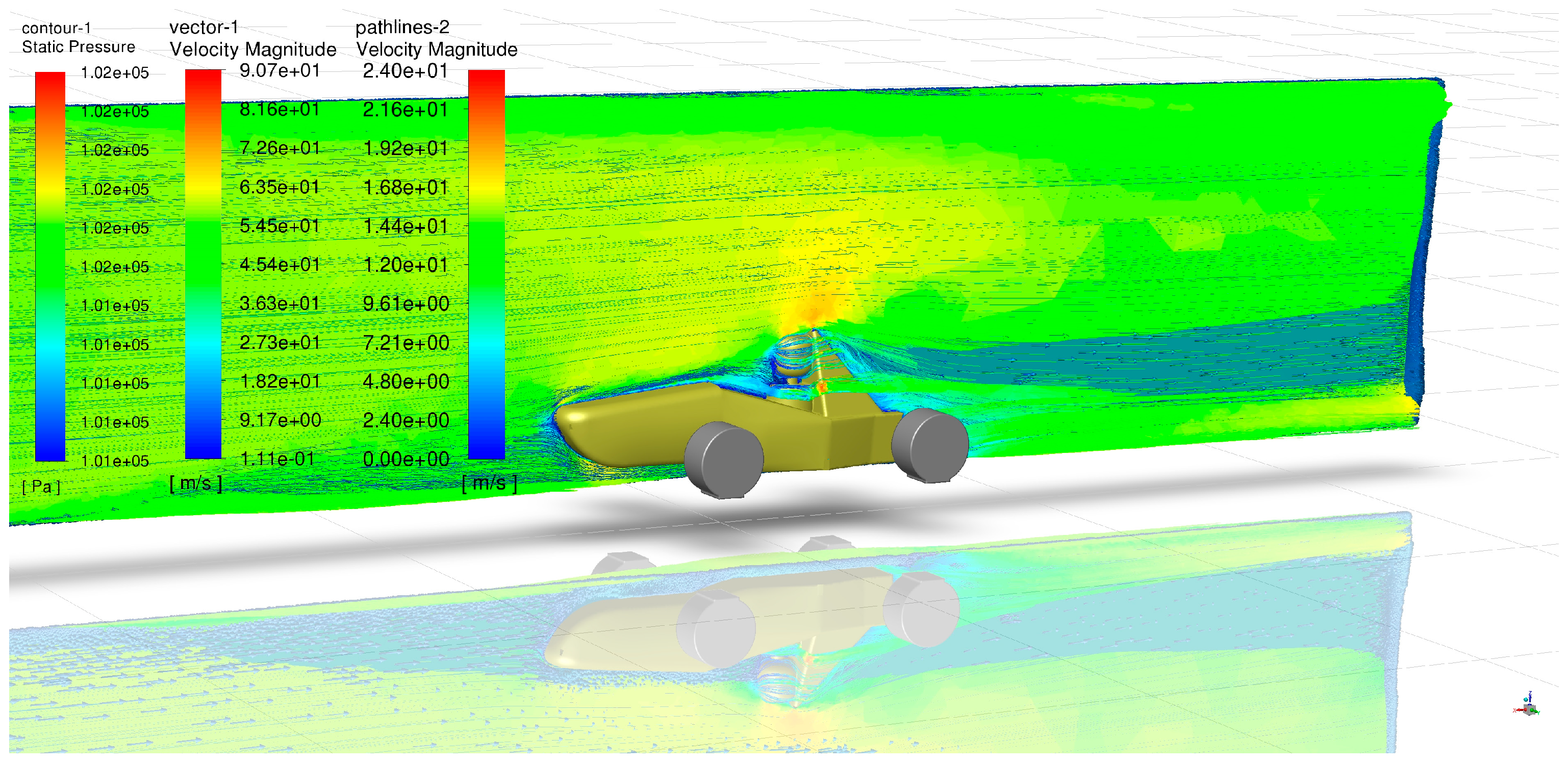
Figure 20.
Body mold.

Figure 21.
The car body after vacuuming.
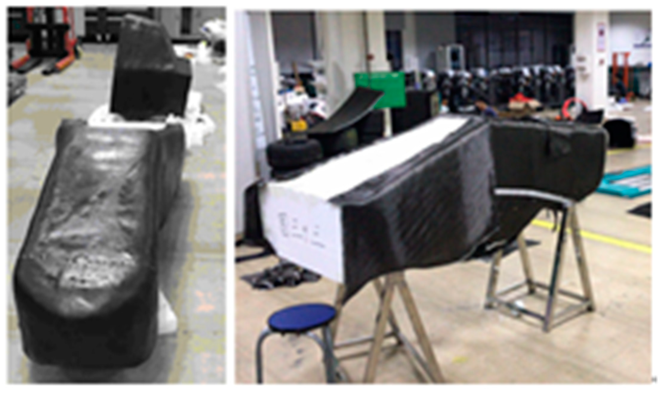
Figure 22.
The car body and integrated car body.

Table 1.
Approximate air drag resistance coefficients of various shapes.
| Name | Sphere | Half- Sphere | Cone | Cube | Angled Cube | Long Cylinder | Short Cylinder | Streamlined Body | Streamlined Half-Body |
|---|---|---|---|---|---|---|---|---|---|
| Shape | ○ |  | △ | □ | ◇ |  |  |  |  |
| coefficient | 0.47 | 0.42 | 0.5 | 1.05 | 0.8 | 0.82 | 1.15 | 0.04 | 0.09 |
Table 2.
Flow field area size table.
| Front Size | Rear Size | Total Width | Height | |
|---|---|---|---|---|
| Relative size | 2~3 times vehicle width length | 7~8 times vehicle width length | 3~4 times the vehicle width | 3~4 times vehicle height |
| Actual size | 6 m | 22 m | 8 m | 5 m |
Table 3.
Comparison of aerodynamic performance of racecar body.
| Aerodynamic Resistance (N) | Aerodynamic Lift (N) | |
|---|---|---|
| Previous generation body | 43.5 | 24.1 |
| Newly designed body | 30.5 | 20.5 |
| Comparison between two bodies | 13 | 3.6 |
Disclaimer/Publisher’s Note: The statements, opinions and data contained in all publications are solely those of the individual author(s) and contributor(s) and not of MDPI and/or the editor(s). MDPI and/or the editor(s) disclaim responsibility for any injury to people or property resulting from any ideas, methods, instructions or products referred to in the content. |
© 2024 by the authors. Licensee MDPI, Basel, Switzerland. This article is an open access article distributed under the terms and conditions of the Creative Commons Attribution (CC BY) license (https://creativecommons.org/licenses/by/4.0/).
Share and Cite
MDPI and ACS Style
Li, J.; Liu, F.; Wang, L. Design and Aerodynamic Characteristics Analysis of an Electric Racecar Body Based on CFD. World Electr. Veh. J. 2024, 15, 192. https://doi.org/10.3390/wevj15050192
AMA Style
Li J, Liu F, Wang L. Design and Aerodynamic Characteristics Analysis of an Electric Racecar Body Based on CFD. World Electric Vehicle Journal. 2024; 15(5):192. https://doi.org/10.3390/wevj15050192
Chicago/Turabian StyleLi, Jixiong, Fengbi Liu, and Lei Wang. 2024. "Design and Aerodynamic Characteristics Analysis of an Electric Racecar Body Based on CFD" World Electric Vehicle Journal 15, no. 5: 192. https://doi.org/10.3390/wevj15050192