Article

Multiple Synchronous Rotating Frame Transformation-Based 12th Current Harmonic Suppression Method for an IPMSM

1
Weichai Power Co., Ltd., Weifang 261061, China
2
Advanced Electrical Equipment Innovation Center, Zhejiang University, Hangzhou 311107, China
3
School of Electrical Engineering, Tiangong University, Tianjin 300387, China
*
Author to whom correspondence should be addressed.
World Electr. Veh. J. 2022, 13(10), 194; https://doi.org/10.3390/wevj13100194
Submission received: 2 September 2022 / Revised: 5 October 2022 / Accepted: 17 October 2022 / Published: 20 October 2022

Abstract

:
In order to solve the problem that the three-phase current of the interior permanent magnet synchronous motor (IPMSM) contains the 11th and 13th current harmonics, a multiple synchronous rotating frame transformation (MSRFT)-based current harmonic suppression method is established. Firstly, the influencing factors of current harmonics in IPMSM vector control are analyzed, and the influence mechanism of the inverter’s dead-time effect and the permanent magnet flux linkage harmonics on the current harmonics is described. Secondly, a simple current harmonic extraction method is proposed by optimizing the traditional current harmonic extraction method based on MSRFTs. The proposed method achieves the accurate extraction of the current harmonic components. Thirdly, a harmonic voltage generation method is established and is combined with the proposed current harmonic extraction method to form a current harmonic suppression strategy. Finally, the feasibility and effectiveness of the proposed method are verified via MATLAB/Simulink simulations and experiments. The simulation and experimental results show that the proposed current harmonic extraction method can extract the current harmonic components accurately, and the proposed current harmonic suppression strategy can suppress the 11th and 13th current harmonics effectively.

1. Introduction

Interior permanent-magnet synchronous motors (IPMSMs) are widely used in electric vehicle drive systems due to their compact structure, high power density, and wide field-weakening range. Ideally, the phase currents of the motor should be standard sinusoidal waveforms. However, in the actual operation of an IPMSM, the nonideal factors will cause the phase current of the motor to contain certain harmonics that will cause torque fluctuations and unnecessary motor losses. It is very important to effectively suppress the current harmonics to ensure the steady-state operation quality of the IPMSM.
The essential cause of the current harmonics is the nonsinusoidal voltage, while the nonlinearity of the inverter and the nonsinusoidal permanent magnet flux linkage are the important reasons for the existence of harmonics in the voltage. The existing current harmonic suppression strategies are mainly divided into two categories.
The first type of strategy is used to construct current controllers with harmonic suppression. Some scholars have constructed current controller structures with a repetitive controller and a PI controller in parallel to suppress the current harmonics of a specific order [1,2,3]. Similarly, some scholars have applied proportional resonance controllers to achieve the suppression of main-frequency current harmonics [4,5,6]. This kind of control method can effectively suppress the current harmonics of a specific order. However, the coefficients of the controller often need to be adaptively adjusted with the speed, so there are certain limitations in its application.
The voltage harmonic injection method is another effective current harmonic suppression method. Some scholars generate harmonic voltages by analyzing the nonlinear characteristics of the inverter, using online observations of the terminal voltage, a flux linkage observer, and real-time calculations of the compensation voltage. Then, the harmonic voltage is injected into the control system to cancel the voltage harmonics caused by the nonlinearity of the inverter, so as to achieve the suppression of the current harmonics [7,8]. However, these methods can only effectively suppress the current harmonics caused by the dead-time effect. In addition, some scholars have proposed a current harmonic suppression strategy based on the adaptive linear neuron method. Two linear neurons are first used to estimate the 6th current harmonic components and then two linear neurons are used to generate the injected voltage harmonics [9,10]. This method can effectively suppress the 6th current harmonics, but the algorithm is more complicated.
In recent years, some scholars have proposed a current harmonic suppression strategy based on multiple synchronous rotating frame transformations (MSRFTs), which consists of two parts: the current harmonic extraction and voltage harmonic generation. For the current harmonic extraction part, some scholars convert the three-phase current from an AC component to a DC component through the same coordinate transformation process as the current harmonic frequency, and combine the low-pass filter (LPF) to extract the current harmonic component [11,12]. However, for the high-current motors used in electric vehicles, the amplitude of the fundamental current is much larger than the harmonic content. Therefore, it is difficult for the LPF to completely filter out the fundamental current, which affects the accuracy of the current harmonic extraction. In order to improve the accuracy of the current harmonic extraction, a closed-loop detection method was proposed in [13]. This method achieves the accurate extraction of current harmonic components through the principle of feedback, but the control structure is complicated. An extraction method based on a type II Chebyshev filter was proposed in [14], but it also increased the algorithm’s complexity. In order to achieve the fast and accurate extraction of current harmonic components, the current average method was proposed in [15,16]. However, the half-wave asymmetry of the input current in the average current value method will generate an unnecessary integral current and affect the extraction accuracy of the current harmonic components. For the voltage harmonic generation part, the extracted 5th and 7th order current harmonic components are usually compared with 0 and then respectively pass through the PI controller to generate the harmonic voltage. This voltage is injected into the d-q axis voltage after the inverse MSRFT.
For IPMSMs, the question of how to better suppress the current harmonics is a very meaningful and challenging task. The 11th and 13th harmonic components in the three-phase coordinate system of some motors account for the main part. At present, there are very few papers on this subject. Based on this research background, the suppression methods of the 11th and 13th current harmonics are studied in this paper. Firstly, the influencing factors of the current harmonics in the vector control system of the IPMSM are theoretically analyzed, and the influence mechanism of the inverter dead-time effect and the permanent magnet flux linkage harmonics on the current harmonics is expounded. Secondly, based on the MSRFT, the accurate extraction of the 12th harmonic current amplitude in the d-q axis current is achieved. Thirdly, based on the extracted harmonic current amplitudes, a harmonic voltage generation strategy is established to achieve the suppression of the 12th harmonic. Finally, the feasibility and effectiveness of the proposed method are verified via MATLAB/Simulink simulations and experiments.

2. Current Harmonic Analysis of IPMSM Vector Control System Considering Back-EMF Nonsinusoidal and Dead-Time Effects

2.1. IPMSM Harmonic Mathematical Model in Vector Control System

Considering the permanent magnet flux linkage harmonics and the inverter dead-time effect, the stator voltage harmonics of the IPMSM in the d-q axis coordinate system can be expressed as:
{ v d h _ M = R i d h + L d d i d h d t ω e L q i q h + d λ d h d t ω e λ q h Δ v d h 1 + Δ v d h 2 v q h _ M = R i q h + L q d i q h d t + ω e L d i d h + d λ q h d t + ω e λ d h Δ v q h 1 + Δ v q h 2
where vdh_M and vqh_M are the sum of all order stator voltage harmonics of the IPMSM in the d-q axis coordinate system; R is the motor stator resistance value; idh and iqh are the sum of all order stator current harmonics of the IPMSM in the d-q axis coordinate system; λdh and λqh are the sum of all order permanent magnet flux linkage harmonics of the IPMSM in d-q axis coordinate system, ωe is the electrical angular velocity of the motor; Δvdh1 and Δvqh1 are the voltage harmonics caused by the permanent magnet flux linkage harmonics; Δvdh2 and Δvqh2 are the voltage harmonics caused by the inverter’s dead-time effect.

2.2. Analysis of Permanent Magnet Flux Harmonics and Current Harmonics

Normally, the permanent magnet flux of the motor is not completely sinusoidal in the three-phase coordinate system due to the influence of the machining technology of the motor and the method of wire embedding. Therefore, there are permanent magnet flux harmonics in the motor. The no-load back-EMF waveform of the tested motor and its fast Fourier transform (FFT) analysis results are shown in Figure 1.
In the three-phase coordinate system, the permanent magnet flux linkages considering the 11th and 13th harmonics can be expressed as:
[ λ a λ b λ c ] = [ λ s n cos ( n ω e t + θ n ) λ s n cos [ n ( ω e t 2 3 π ) + θ n ] λ s n cos [ n ( ω e t + 2 3 π ) + θ n ] ] , n = 1 ,   11 ,   13
where λsn and θn are the amplitude and initial phase angle of the permanent magnet flux linkage harmonics of each order, respectively.
The transformation matrix used to convert the three-phase coordinate system to the synchronous rotating coordinate system can be expressed as:
T a b c / d q = 2 3 [ cos ( ω e t ) cos ( ω e t 2 3 π ) cos ( ω e t + 2 3 π ) sin ( ω e t ) sin ( ω e t 2 3 π ) sin ( ω e t + 2 3 π ) ]
Multiplying Equations (2) and (3), the permanent magnet flux linkage harmonics in the d-q axis coordinate system can be expressed as:
[ λ d h 12 λ q h 12 ] = [ λ s 13 cos ( 12 ω e t + θ 13 ) + λ s 11 cos ( 12 ω e t + θ 11 ) λ s 13 sin ( 12 ω e t + θ 13 ) λ s 11 sin ( 12 ω e t + θ 11 ) ]
where λdh12 and λqh12 are the 12th permanent magnet flux linkage harmonics in the d-q axis coordinate system, respectively.
Equation (4) can be further simplified as:
[ λ d h 12 λ q h 12 ] = [ χ d h 12 cos ( 12 ω e t + α 12 ) χ q h 12 sin ( 12 ω e t + α 12 ) ]
where χdh12, χqh12, αd12, and αq12 are the amplitude and initial phase angle of the 12th permanent magnet flux linkage harmonics, respectively.
[ χ d h 12 χ q h 12 ] = [ ( λ s 11 sin θ 11 + λ s 13 sin θ 13 ) 2 + ( λ s 11 cos θ 11 + λ s 13 cos θ 13 ) 2 ( λ s 11 sin θ 11 λ s 13 sin θ 13 ) 2 + ( λ s 11 cos θ 11 λ s 13 cos θ 13 ) 2 ] ,   [ α d h 12 α q h 12 ] = [ arctan ( λ s 13 sin θ 13 + λ s 11 sin θ 11 λ s 13 cos θ 13 + λ s 11 cos θ 11 ) arctan ( λ s 13 sin θ 13 λ s 11 sin θ 11 λ s 13 cos θ 13 λ s 11 cos θ 11 ) ]
In the d-q axis coordinate system, the 12th current harmonic caused by the permanent magnet flux linkage harmonics can be expressed as:
[ i d h 112 i q h 112 ] = [ I d h 112 sin ( 12 ω e t + μ d 12 ) I q h 112 cos ( 12 ω e t + μ q 12 ) ]
where Idh112, Iqh112, μd12, and μq12 are the amplitude and initial phase angle of the 12th voltage harmonics caused by the permanent magnet flux linkage harmonics, respectively.
Without considering the voltage harmonics caused by the dead-time effect, by substituting Equation (5) into Equation (1), the relationship between the 12th current harmonics and the permanent magnet flux linkage harmonics can be expressed as:
{ i d h 112 = ω e ( χ q h 12 sin α q 12 + 12 χ d h 12 sin α d 12 ) 2 + ( χ q h 12 cos α q 12 + 12 χ d h 12 cos α d 12 ) 2 R 2 + ( 12 ω e L d ) 2 sin ( 12 ω e t + μ d 12 ) i q h 112 = ω e ( 12 χ q h 12 sin α q 12 + χ d h 12 sin α d 12 ) 2 + ( 12 χ q h 6 cos α q 12 + χ d h 6 cos α d 12 ) 2 R 2 + ( 12 ω e L q ) 2 cos ( 12 ω e t + μ q 12 )

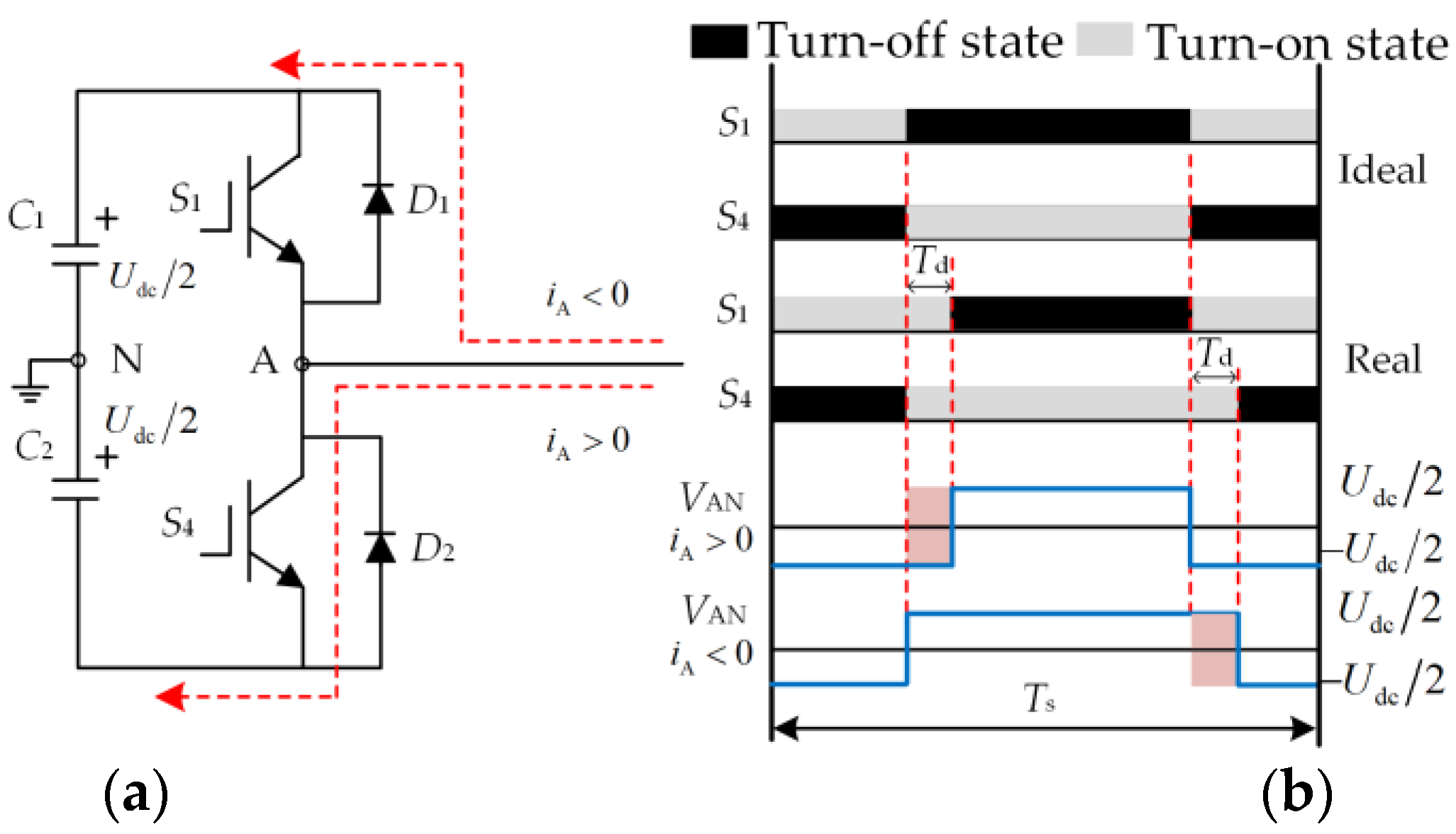
2.3. Analysis of the Inverter’s Dead-Time Effect and Current Harmonics

The switching state of the upper and lower bridge arms of the A-phase of the inverter is shown in Figure 2. The dead time is often set to prevent the straight-through effect of the upper and lower bridge arms. In the d-q axis coordinate system, the voltage error caused by the inverter dead-time effect can be expressed as:
[ Δ v d h 2 Δ v q h 2 ] = 4 V d e a d π [ sin γ n = 6 k { sin [ n ( ω e t + γ ) γ ] n 1 + sin [ n ( ω e t + γ ) + γ ] n + 1 } cos γ n = 6 k { cos [ n ( ω e t + γ ) γ ] n 1 cos [ n ( ω e t + γ ) + γ ] n + 1 } ]
where Vdead is the voltage loss caused by the inverter dead-time effect; γ is the angle between the current vector and the q-axis; k = 1, 2, 3….
The 12th voltage harmonics caused by the inverter dead-time effect can be expressed as:
[ Δ v d h 212 Δ v q h 212 ] = 4 V d e a d π [ sin ( 12 ω e t + 11 γ ) 11 sin ( 12 ω e t + 13 γ ) 13 cos ( 12 ω e t + 11 γ ) 11 + cos ( 12 ω e t + 13 γ ) 13 ]
where Δvdh212 and Δvqh212 are the 12th voltage harmonics caused by the inverter dead-time effect in the d-q axis coordinate system, respectively.
Equation (9) can be further simplified as:
[ Δ v d h 212 Δ v q h 212 ] = [ V d h 212 sin ( 6 ω e t + ϕ d 12 ) V q h 212 cos ( 6 ω e t + ϕ q 12 ) ]
where Vdh212, Vqh212, ϕd12, and ϕq12 are the amplitudes and initial phase angles of the 12th voltage harmonics caused by the inverter dead-time effect, respectively.
[ V d h 212 V q h 212 ] = 4 V d e a d 143 π [ ( 13 sin 11 γ + 11 sin 13 γ ) 2 + ( 13 cos 11 γ + 11 cos 13 γ ) 2 ( 13 sin 11 γ 11 sin 13 γ ) 2 + ( 13 cos 11 γ + 11 cos 13 γ ) 2 ] ,   [ ϕ d h 12 ϕ q h 12 ] = [ arctan ( 11 sin 13 γ + 13 sin 11 γ 11 cos 13 γ + 13 cos 11 γ ) arctan ( 11 sin 13 γ 13 sin 11 γ 11 cos 13 γ 13 cos 11 γ ) ] ,
In the d-q axis coordinate system, the 12th current harmonics caused by the dead-time effect of the inverter can be expressed as:
[ i d h 212 i q h 212 ] = [ I d h 212 sin ( 12 ω e t + σ d h 12 ) I q h 212 cos ( 12 ω e t + σ q h 12 ) ]
where Idh212, Iqh212, σd12, and σq12 are the amplitudes and initial phase angles of the 12th current harmonics caused by the inverter dead-time effect, respectively.
It is assumed that the coupling of the harmonic current is well decoupled by the feedforward decoupling, so only the voltage harmonics caused by the dead-time effect are analyzed. Substituting Equations (10) and (11) into Equation (1), the current harmonic calculation formula can be expressed as:
{ i d h 212 = V d h 212 R 2 + ( 12 ω e L d ) 2 sin ( 12 ω e t + σ d h 12 ) i q h 212 = V q h 212 R 2 + ( 12 ω e L q ) 2 cos ( 12 ω e t + σ q h 12 )

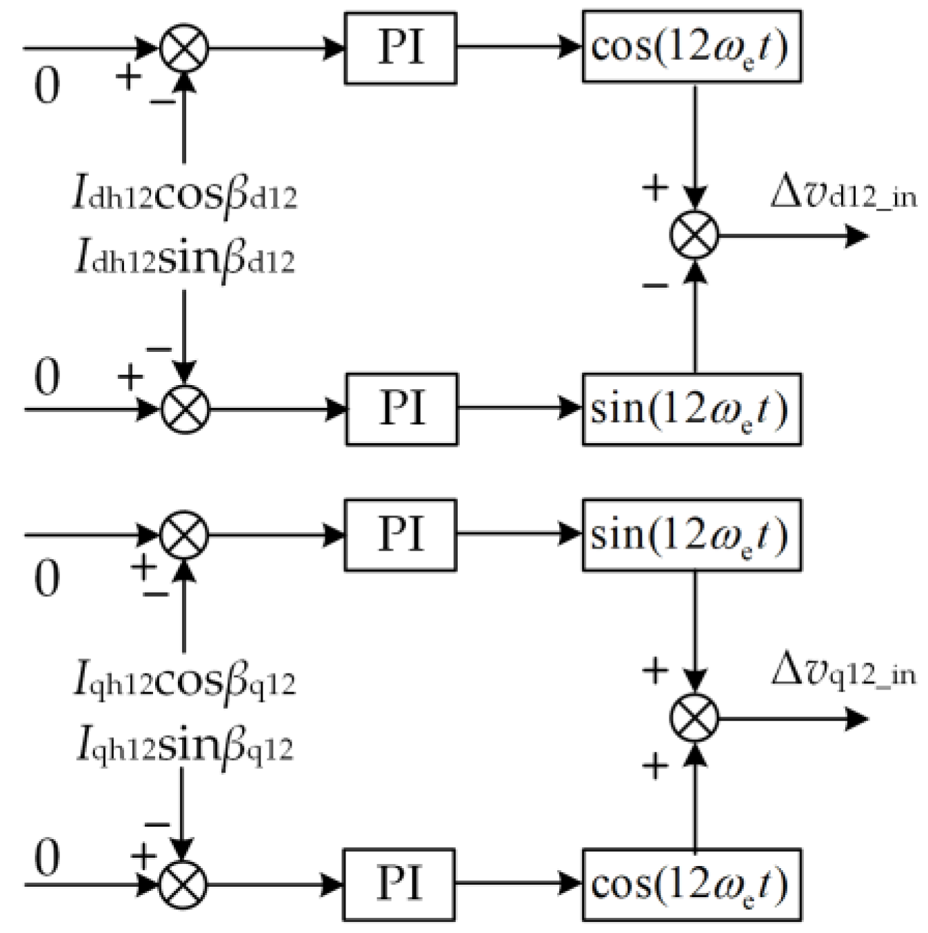
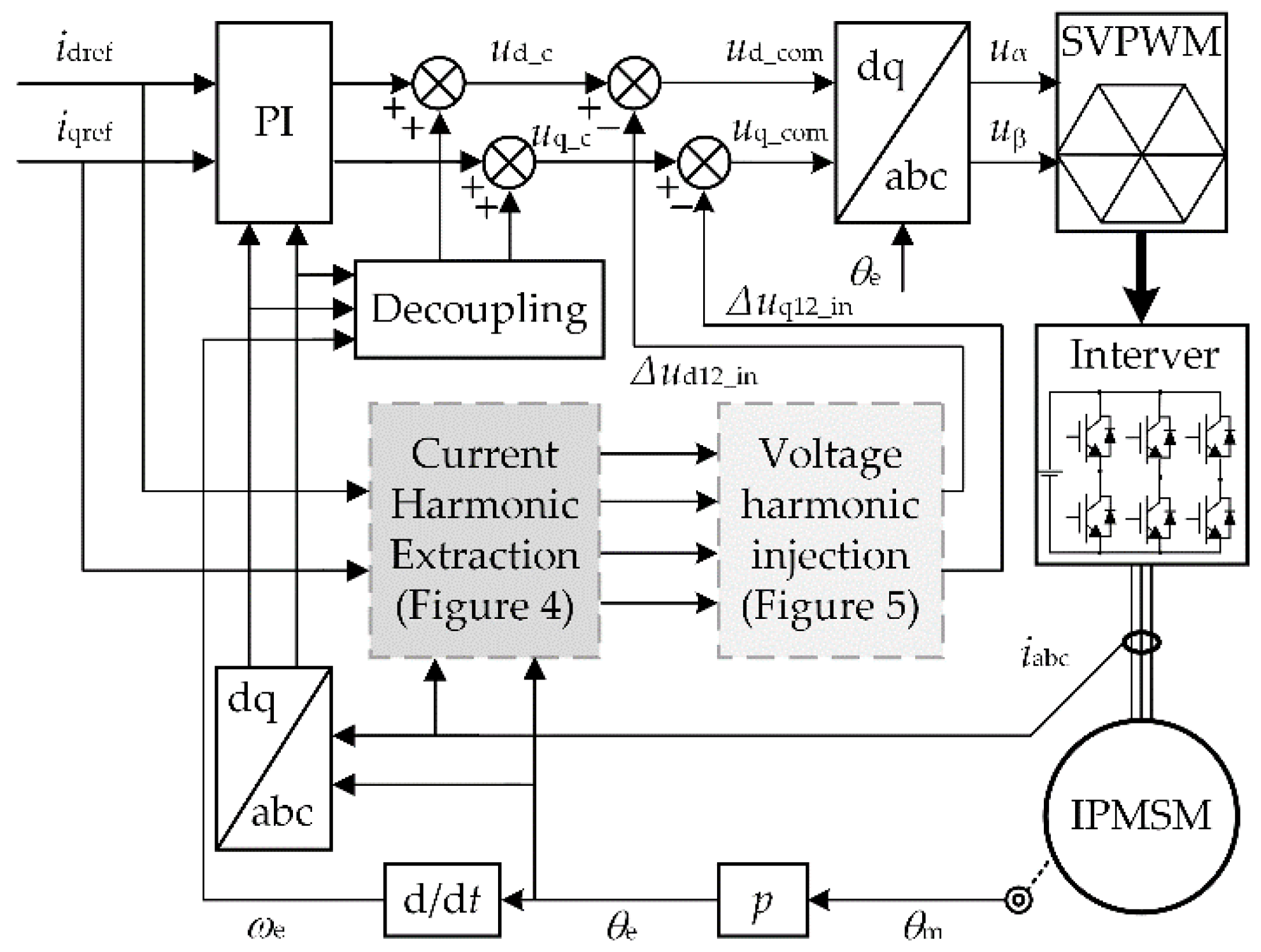
3. The Proposed Current Harmonic Suppression Strategy

In order to suppress the current harmonics excellently, the accuracy of the current harmonic extraction is particularly important. An LPF is commonly used to extract the current harmonics. The traditional current harmonic extraction method is shown in Figure 3.
After the 11th and 13th coordinate transformation of the three-phase current, the fundamental component of the three-phase current will appear as the 12th harmonic component, while the 11th and 13th harmonics of the three-phase current will appear as the DC component. Since the amplitude of the 12th harmonic component in the current obtained after the 11th and 13th coordinate transformation is much larger than that of the DC component, the amplitude of the 12th harmonic component after being filtered by the LPF is still not negligible compared to the DC component. Therefore, it is difficult to accurately extract the harmonic current using traditional methods. In order to improve the accuracy of the harmonic current extraction, PI-based closed-loop control methods or other complex filter methods have been proposed by some scholars, but this undoubtedly increases the complexity of the algorithm.
In order to extract the harmonic components of the phase current simply and accurately, a current harmonic extraction method based on MSRFTs is proposed in this paper. The motor phase currents considering the 11th and 13th harmonics can be expressed as:
[ i a i b i c ] = [ I s n cos ( n ω e t + η n ) I s n cos [ n ( ω e t 2 3 π ) + η n ] I s n cos [ n ( ω e t + 2 3 π ) + η n ] ] , n = 1 ,   11 ,   13
where ia, ib, and ic are the three-phase currents; Isn and ηn are the amplitude and initial phase angle of each harmonic order in the phase current, respectively.
After Equation (13) is transformed by Equation (3), the three-phase current can be expressed as:
[ i d h 12 i q h 12 ] = [ I s 13 cos ( 12 ω e t + η 13 ) + I s 11 cos ( 12 ω e t + η 11 ) I s 13 sin ( 12 ω e t + η 13 ) I s 11 sin ( 12 ω e t + η 11 ) ]
where idh12 and iqh12 are the 12th current harmonics in the d-q axis coordinate system, respectively.
Equation (15) can be further simplified as:
[ i d h 12 i q h 12 ] = [ I d h 12 cos ( 12 ω e t + β d 12 ) I q h 12 sin ( 12 ω e t + β q 12 ) ]
where Idh12, Iqh12, βd12, and βq12 are the 12th current harmonic amplitudes and initial phase angles in the d-q axis coordinate system, respectively.
[ I d h 12 I q h 12 ] = [ ( I s 11 sin η 11 + I s 13 sin η 13 ) 2 + ( I s 11 cos η 11 + I s 13 cos η 13 ) 2 ( I s 11 sin η 11 I s 13 sin η 13 ) 2 + ( I s 11 cos η 11 I s 13 cos η 13 ) 2 ] ,   [ β d h 12 β q h 12 ] = [ arctan ( I s 13 sin η 13 + I s 11 sin η 11 I s 13 cos η 13 + I s 11 cos η 11 ) arctan ( I s 13 sin η 13 I s 11 sin η 11 I s 13 cos η 13 I s 11 cos η 11 ) ]
Equation (15) describes the relationship between the 12th harmonic current and the 11th and 13th harmonics in the phase current in the d-q axis coordinate system.
The current harmonic extraction method proposed in this paper is shown in Figure 4. Firstly, the fundamental phase current is reconstructed from the d-q axis reference currents. Secondly, the fundamental phase current in Equation (13) is subtracted to obtain the harmonic components in the three-phase current. Thirdly, the obtained harmonic components are subjected to the coordinate transformation shown in Equations (16) and (17). Finally, after filtering the result obtained by the coordinate transformation, the 12th current harmonic components shown in Equations (18) and (19) can be obtained.
T a b c / d q 11 = 2 3 [ cos ( 11 ω e t ) cos [ 11 ( ω e t 2 3 π ) ] cos [ 11 ( ω e t + 2 3 π ) ] sin ( 11 ω e t ) sin [ 11 ( ω e t 2 3 π ) ] sin [ 11 ( ω e t + 2 3 π ) ] ]
T a b c / d q 13 = 2 3 [ cos ( 13 ω e t ) cos [ 13 ( ω e t 2 3 π ) ] cos [ 13 ( ω e t + 2 3 π ) ] sin ( 13 ω e t ) sin [ 13 ( ω e t 2 3 π ) ] sin [ 13 ( ω e t + 2 3 π ) ] ]
[ I d h 12 cos β d 12 I q h 12 sin β d 12 ] = [ I s 11 cos η 11 + I s 13 cos η 13 I s 11 sin η 11 + I s 13 sin η 13 ]
[ I d h 12 cos β q 12 I q h 12 sin β q 12 ] = [ I s 11 cos η 11 I s 13 cos η 13 I s 11 sin η 11 I s 13 sin η 13 ]
After passing the extracted current harmonic components through the desired voltage harmonic generation module as shown in Figure 5, the voltage required to suppress the current harmonic to 0 can be generated. The whole block diagram of the current harmonic suppression strategy is shown in Figure 6.

4. Simulation Results

In order to verify the effectiveness of the proposed strategy, the simulation verification is carried out on the MATLAB/Simulink platform. The parameters of the IPMSM and controller are shown in Table 1.

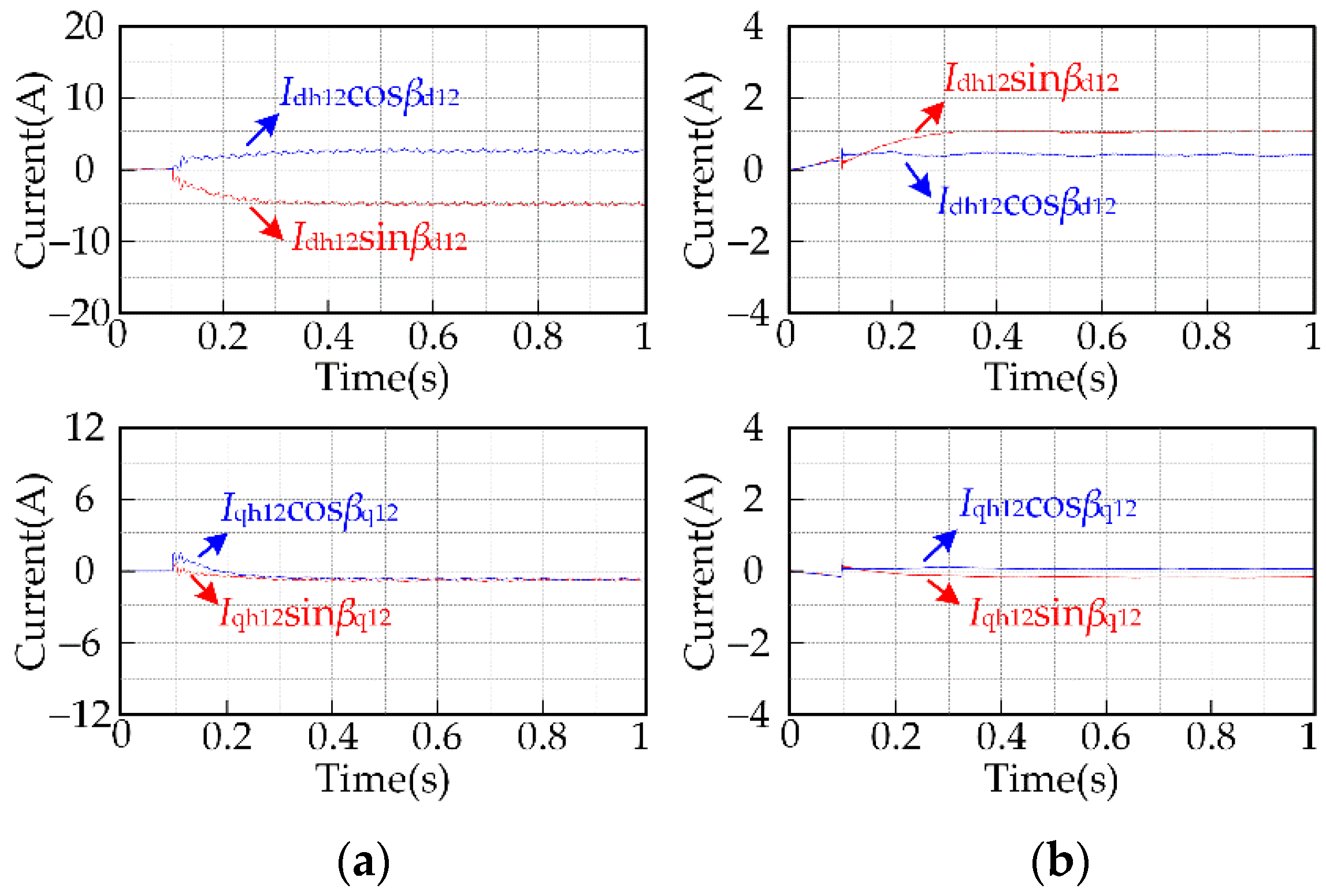
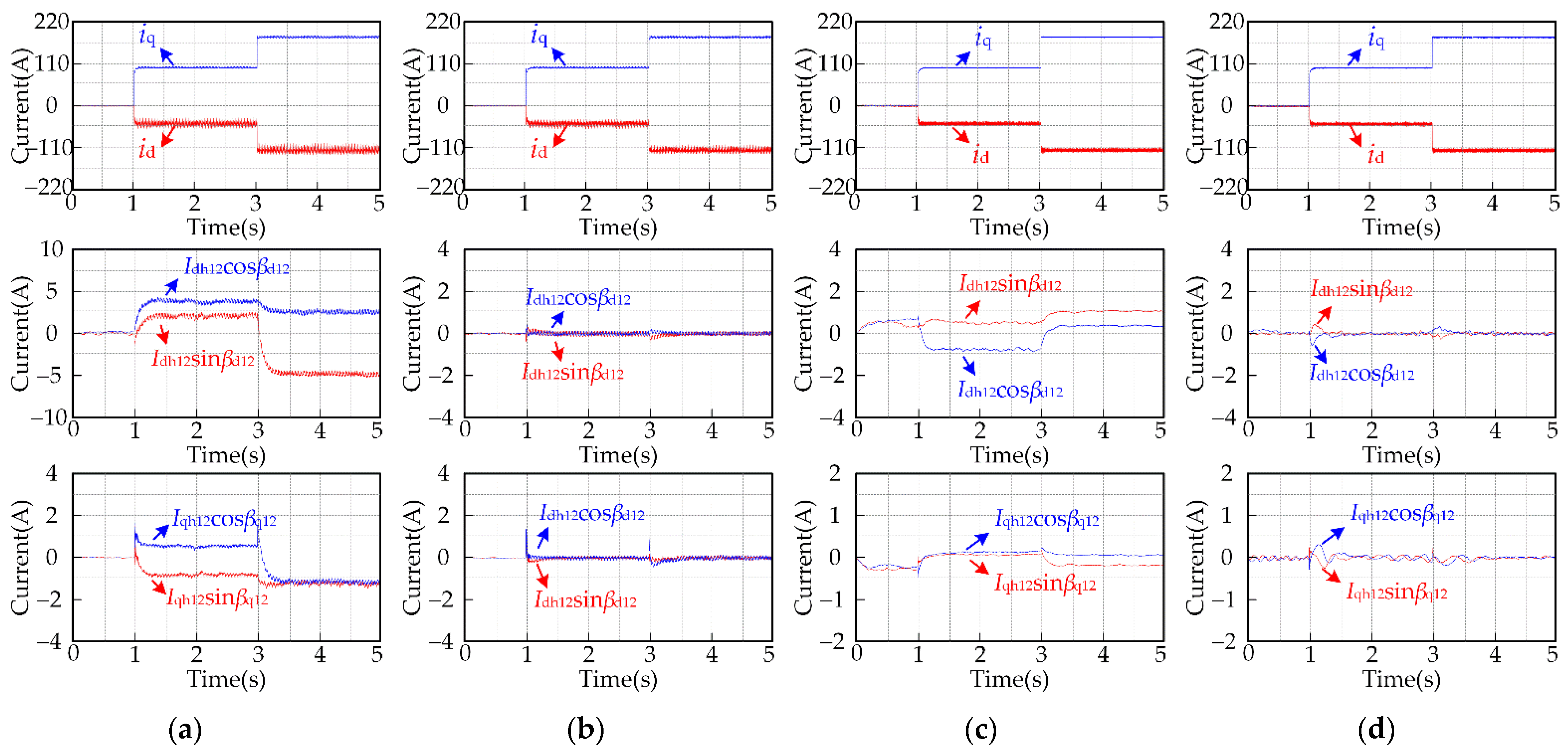
4.1. Simulation Results for the Proposed Harmonic Extraction Method

For motor speeds of 100 rpm and 3000 rpm and a load torque of 30 Nm, the results of the 12th current harmonic components extracted by the traditional method are shown in Figure 7. In the simulation, the cutoff frequency of the FLPF is 2 Hz.
It can be seen from Figure 7a that when the motor speed is low, the current harmonic components extracted by the traditional method contain high-amplitude AC components, so with the traditional method it is difficult to obtain accurate current harmonic components. It can be seen from Figure 7b that when the motor speed is high, the amplitude of the AC components in the extracted current harmonic components is small. This is because the frequency of the AC components in the input current of the filter is relatively large, and the filter has a strong ability to attenuate high-frequency signals. However, the filter cannot completely attenuate the signal to 0, so the traditional method still cannot accurately obtain the current harmonic components when the motor speed is high.
For motor speeds of 100 rpm and 3000 rpm and a load torque of 30 Nm, the results of the 12th current harmonic components extracted by the proposed method are shown in Figure 8. Likewise, the cutoff frequency of the FLPF is 2 Hz.
Comparing Figure 7 and Figure 8, it can be seen that no matter whether the motor runs at low speed or high speed, the amplitude of the alternating current contained in the current harmonic components extracted by the proposed method is smaller than that obtained by the traditional method. This is because the proposed method eliminates the high-amplitude fundamental current in the three-phase current by reconstructing the input current of the filter. Therefore, the current harmonic components extracted by the proposed method are more accurate than those extracted by the traditional method.

4.2. Simulation Results for the Proposed Current Harmonic Suppression Strategy

For motor speeds of 100 rpm and 3000 rpm with load torque changes from 0 Nm to 30 Nm and then to 72 Nm, the d-q axis current waveforms and the 12th current harmonic component waveforms before and after applying the proposed current harmonic suppression strategy are shown in Figure 9.
It can be seen from Figure 9 that no matter whether the motor runs at low speed or high speed, after applying the proposed current harmonic suppression strategy, the amplitude of the 12th current harmonic component can be controlled to 0 under different load torques. This also shows that the amplitudes of the 11th and 13th harmonic components in the three-phase current are controlled to be 0.
For a motor speed of 500 rpm and a load torque of 72 Nm, the three-phase current waveforms and the FFT results of the A-phase current before and after applying the current harmonic suppression strategy are shown in Figure 10.
It can be seen from Figure 10 that when the motor runs at 500 rpm, the amplitudes of the 11th and 13th current harmonic components decrease from 1.18% and 1.57% of the fundamental amplitude to 0.07% and 0.09%, respectively, and the total harmonic distortion (THD) value decreases from 3.21% to 2.29%.
The simulation results show that the proposed current harmonic suppression strategy can effectively suppress the 11th and 13th harmonics in the IPMSM stator three-phase current.

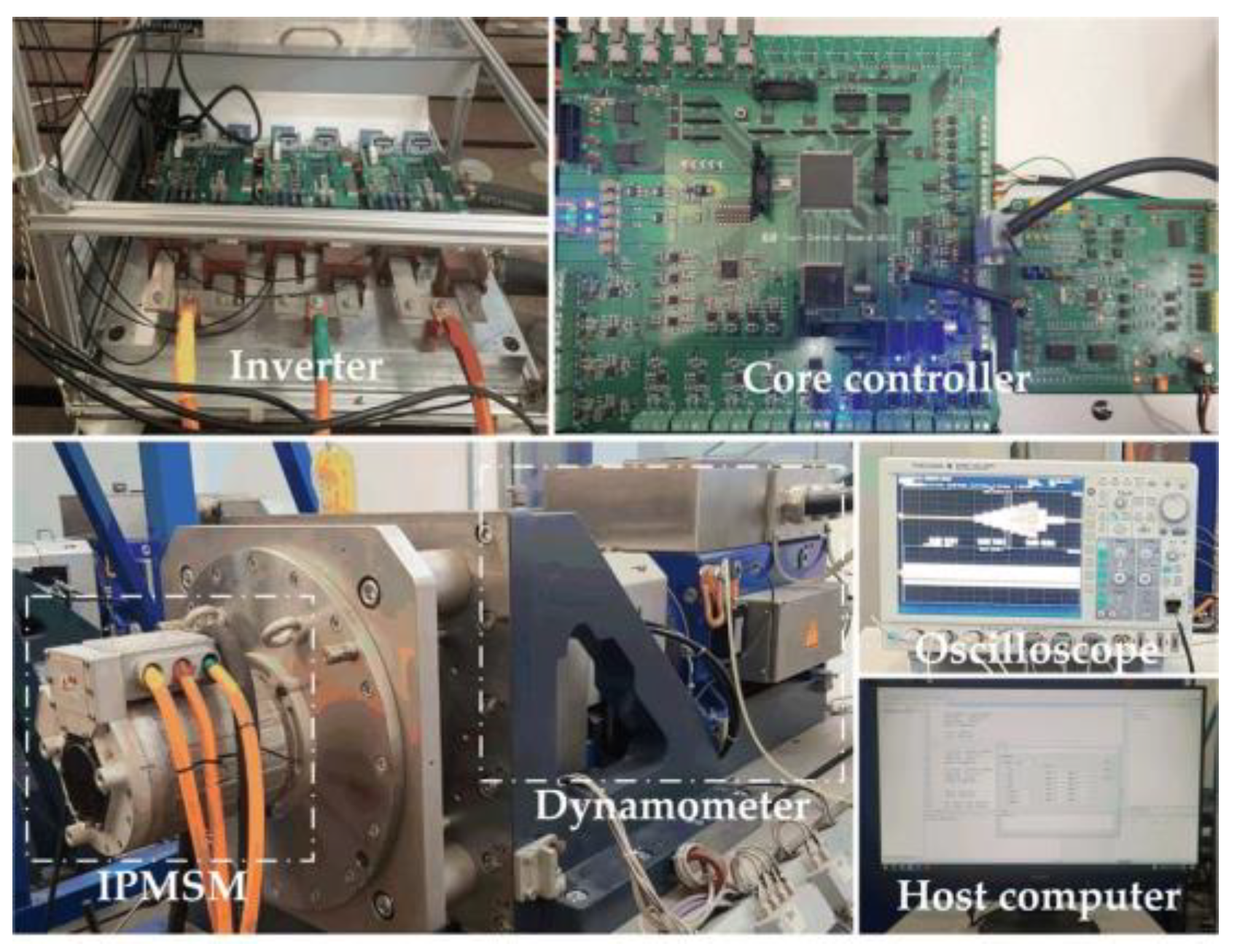
5. Experimental Results

In order to verify the effectiveness and feasibility of the proposed strategy, an experimental system as shown in Figure 11 was built. The control unit is composed of DSP (TMS320F28335) and FPGA (EQ1C6Q240C8). The sampling frequency of the control system is 10 kHz, and the motor load is provided by the dynamometer. The IPMSM and controller parameters are shown in Table 1, and the dead time is 2.6 μs.

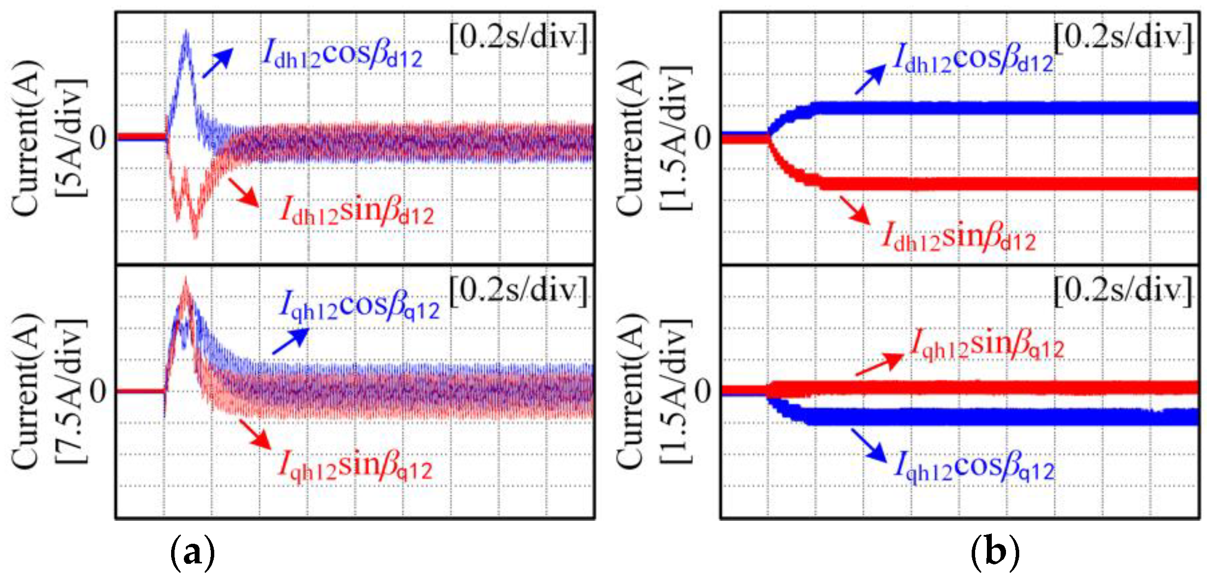
5.1. Experimental Results for the Proposed Harmonic Extraction Method

For motor speeds of 100 rpm and 3000 rpm and a load torque of 30 Nm, the 12th current harmonic components extracted by the traditional method and the proposed method are shown in Figure 12 and Figure 13, respectively. In the experiment, the cutoff frequency of the FLPF was 2 Hz.
It can be seen from Figure 12 that when the rotational speed is low, the current harmonic components extracted by the traditional method contain a relatively large AC component. When the rotation speed is high, the amplitude of the AC component in the harmonic components of the current extracted by the traditional method is reduced, but it cannot be ignored. It can be seen from Figure 12 and Figure 13 that the proposed method can accurately extract the current harmonic components regardless of whether the motor runs at low speed or high speed. This is because the proposed method reconstructs the input current of the filter, so that the input current of the filter does not contain a high-amplitude AC component, which fundamentally solves the problem that the filtered current contains a high-amplitude AC component.

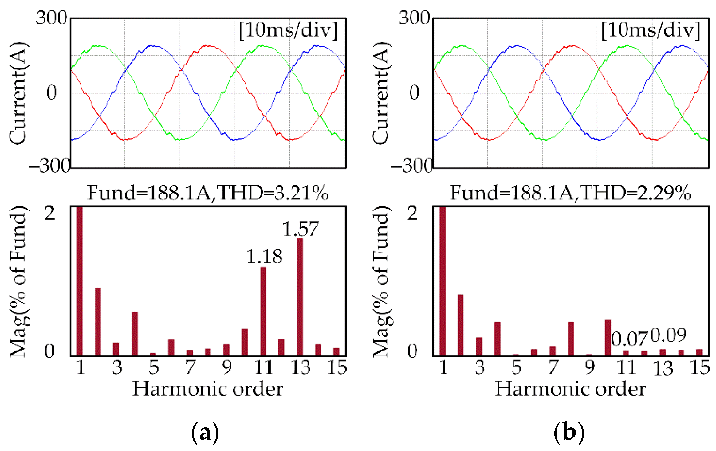
5.2. Experimental Results for the Proposed Current Harmonic Suppresion Strategy

For motor speeds of 100 rpm and 3000 rpm with load torque changes from 0 Nm to 30 Nm and then to 72 Nm, the d-q axis current waveforms and the 12th current harmonic component waveforms before and after applying the proposed current harmonic suppression strategy are shown in Figure 14.
It can be seen from Figure 14 that no matter whether the motor runs at low speed or high speed, after applying the proposed current harmonic suppression strategy, the amplitude of the 12th current harmonic component can be controlled to 0 under different load torques. This also shows that the amplitudes of the 11th and 13th harmonic components in the three-phase current are controlled to be 0.
When the motor speed is 500 rpm and the load torque is 72 Nm, the three-phase current waveforms and the FFT results of the A-phase current before and after applying the current harmonic suppression strategy are shown in Figure 15.
It can be seen from Figure 15 that when the motor runs at 500 rpm, the amplitudes of the 11th and 13th current harmonic components decrease from 0.62% and 0.97% of the fundamental amplitude to 0.11% and 0.14%, respectively, and the THD value decreases from 2.98% to 2.53%.
The experimental results show that the proposed current harmonic suppression strategy can effectively suppress the 11th and 13th harmonics in the IPMSM stator three-phase current.

6. Conclusions

Non-ideal factors will cause the IPMSM stator three-phase current to contain some harmonics, which will cause torque ripple and unnecessary motor losses. In order to solve this problem, a current harmonic suppression strategy based on multiple synchronous rotating frame transformations is proposed in this paper. The main contributions of this study are as follows:
  • The influencing factors of the current harmonics in the IPMSM vector control system were theoretically analyzed, and the influence mechanism of the inverter dead-time effect and permanent magnet flux linkage harmonics on current harmonics was expounded;
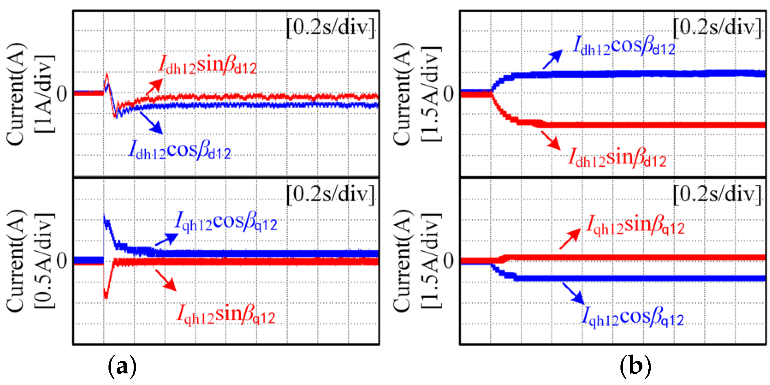
  • Based on the MSRFT, a simple current harmonic extraction method was proposed. The proposed method can accurately extract the 12th current harmonic components in the d-q axis current without increasing the difficulty of the algorithm;
  • Based on the extracted harmonic current components, a harmonic voltage generation strategy was established, and a current harmonic suppression strategy was formed with the proposed current harmonic extraction method;
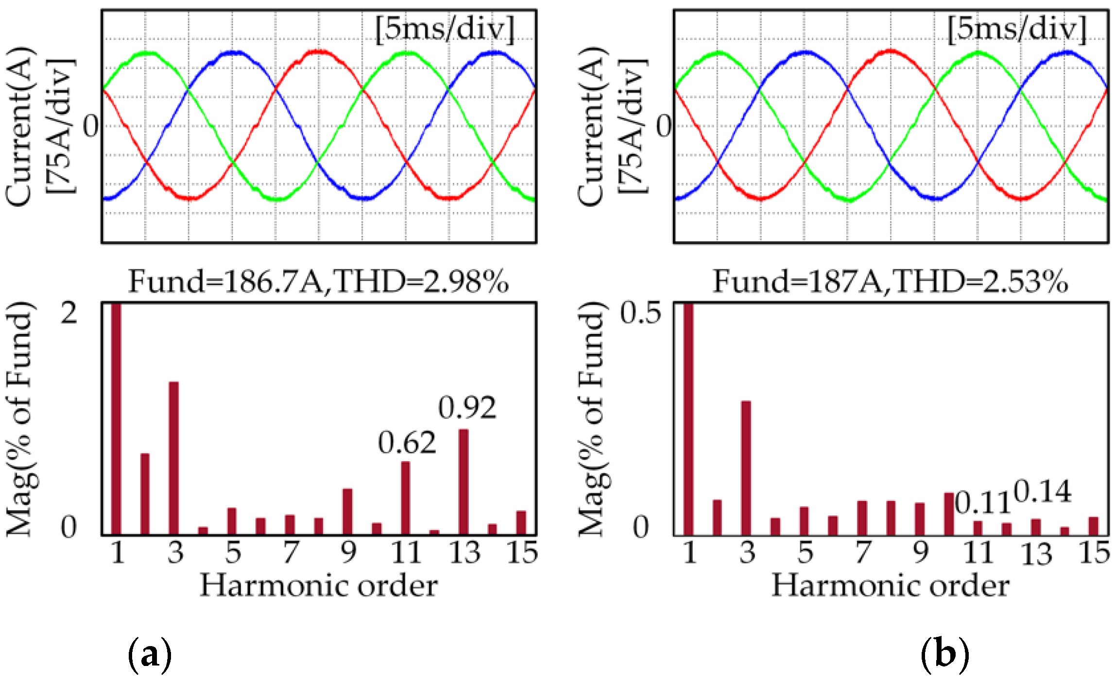
  • The feasibility and effectiveness of the proposed method were verified via MATLAB/Simulink simulations and experiments, respectively. The simulation and experimental results showed that the proposed current harmonic extract method can accurately extract the current harmonic components, and the proposed current harmonic suppression strategy can effectively suppress the 11th and 13th harmonics in the IPMSM stator three-phase current.

Author Contributions

Data curation, Y.X.; formal analysis, Y.X.; funding acquisition, X.L.; investigation, Q.M. and P.Z.; methodology, Y.X.; project administration, Z.L. and X.L.; resources, Z.L.; validation, Z.L. and Y.L.; writing—original draft, Y.L.; writing—review and editing, Y.X. and Y.L. All authors have read and agreed to the published version of the manuscript.

Funding

This research was supported by the Zhejiang Provincial Basic Public Welfare Research Projects under grant numbers LGG22E070010 and LGG22E070011.

Institutional Review Board Statement

Not applicable.

Informed Consent Statement

Not applicable.

Data Availability Statement

Not applicable.

Conflicts of Interest

Y.X., Q.M. and P.Z. are employees of Weichai Power Co., Ltd., Shandong 261061, China. The paper reflects the views of the scientists and not the company.

References

  1. Chen, Z.; Shi, T.; Lin, Z.; Wang, Z.; Gu, X. Analysis and Control of Current Harmonic in IPMSM Field-Oriented Control System. IEEE Trans. Power Electron. 2022, 37, 9571–9585. [Google Scholar] [CrossRef]
  2. Li, Y.; Lu, H.; Qu, W.; Sheng, S. Improved repetitive control for inverter current harmonics suppression. J. Tsinghua Univ. Sci. Technol. 2013, 53, 1030–1035. [Google Scholar]
  3. Tang, Z.; Akin, B. Suppression of Dead-Time Distortion Through Revised Repetitive Controller in PMSM Drives. IEEE Trans. Energy Convers. 2017, 32, 918–930. [Google Scholar] [CrossRef]
  4. Wei, Y.; Luo, X.; Zhu, L.; Zhao, J. Research on current harmonic suppression strategy of high saliency ratio permanent magnet synchronous motor based on proportional resonance controller. Proc. CSEE 2021, 41, 2526–2538. [Google Scholar]
  5. Mai, Z.; Xiao, F.; Liu, J.; Zhang, W.; Liang, C. Harmonic current suppression strategy of dual three-phase permanent magnet synchronous motor based on quasi proportional resonant cascading PI. Trans. CES 2018, 33, 5751–5759. [Google Scholar]
  6. Li, Y.; Lu, H.; Qu, W.; Sheng, S. A permanent magnet synchronous motor current suppression method based on resonant controllers. Proc. CSEE 2014, 34, 423–430. [Google Scholar]
  7. Shen, Z.; Jiang, D. Dead-Time Effect Compensation Method Based on Current Ripple Prediction for Voltage-Source Inverters. IEEE Trans. Power Electron. 2019, 34, 971–983. [Google Scholar] [CrossRef]
  8. Lee, D.; Ahn, J. A simple and Direct Dead-Time Effect Compensation Scheme in PWM-VIS. IEEE Trans. Ind. Appl. 2014, 50, 3017–3025. [Google Scholar] [CrossRef]
  9. Qiu, T.; Wen, X.; Zhao, F. Adaptive-Linear-Neuron-Based Dead-Time Effects Compensation Scheme for PMSM Drives. IEEE Trans. Power Electron. 2016, 31, 2530–2538. [Google Scholar] [CrossRef]
  10. Wang, L.; Zhu, Z.; Bin, H.; Gong, L. Current Harmonic Suppression Strategy for PMSM With Nonsinusoidal Back-EMF Based on Adaptive Linear Neuron Method. IEEE Trans. Ind. Electron. 2022, 67, 9164–9173. [Google Scholar] [CrossRef]
  11. Li, S.; Sun, L.; Liui, X.; An, Q. Current Harmonics Suppression Strategies of Permanent Magnet Synchronous Motor. Trans. CES 2019, 34, 87–96. [Google Scholar]
  12. Yi, P.; Wang, X.; Sun, Z. Instantaneous Harmonic Decomposition Technique for Three-phase Current Based on Multiple Reference Coordinates. IET Electr. Power Appl. 2018, 12, 547–556. [Google Scholar] [CrossRef]
  13. Liu, G.; Chen, B.; Wang, K.; Song, X. Selective Current Harmonic Suppression for High-Speed PMSM Based on High-Precision Harmonic Detection Method. IEEE Trans. Ind. Inform. 2019, 15, 3457–3468. [Google Scholar] [CrossRef]
  14. Wang, W.; Liu, C.; Liu, S.; Song, Z.; Zhao, H.; Dai, B. Current Harmonic Suppression for Permanent-Magnet Synchronous Motor Based on Chebyshev Filter and PI Controller. IEEE Trans. Magn. 2021, 57, 3017671. [Google Scholar] [CrossRef]
  15. Li, S.; Xiao, Y.; Liang, J.; Meng, L. Harmonic Current Suppression of Permanent Magnet Synchronous Motor Based on Closed-Loop Current Average Method. Electr. Mach. Control. Appl. 2019, 46, 51–57. [Google Scholar]
  16. Qi, G.; Wang, Z.; Zhang, L. Research on Harmonic Suppression Strategy of Permanent Magnet Synchronous Motor Stator Phase Current Based on Coordinate Transformation and Current Average Method. Small Spec. Electr. Mach. 2020, 48, 17. [Google Scholar]
Figure 1. Back-EMF waveform and its harmonics spectrum content at no load.
Wevj 13 00194 g001
Figure 2. Schematic diagram of the inverter’s dead time: (a) structural diagram of the A-phase bridge arm; (b) switch tube signal waveform and output voltage waveform.
Wevj 13 00194 g002
Figure 3. Block diagram of the traditional method of current harmonic extraction.
Wevj 13 00194 g003
Figure 4. Block diagram of the proposed method of current harmonic extraction.
Wevj 13 00194 g004
Figure 5. Block diagram of the expected voltage harmonic generation.
Wevj 13 00194 g005
Figure 6. Block diagram of the whole proposed control scheme.
Wevj 13 00194 g006
Figure 7. Simulation results for extracting the 12th current harmonic components using the traditional method: (a) the motor speed is 100 rpm; (b) the motor speed is 3000 rpm.
Wevj 13 00194 g007
Figure 8. Simulation results for extracting the 12th current harmonic components using the proposed method: (a) the motor speed is 100 rpm; (b) the motor speed is 3000 rpm.
Wevj 13 00194 g008
Figure 9. Simulation results for the d-q axis current and 12th current harmonic component: (a) the motor speed is 100 rpm and the proposed strategy is not applied; (b) the motor speed is 100 rpm and the proposed strategy is applied; (c) the motor speed is 3000 rpm and the proposed strategy is not applied; (d) the motor speed is 3000 rpm and the proposed strategy is applied.
Wevj 13 00194 g009
Figure 10. Simulation results for three-phase current waveform and the A-phase current FFT analysis results when the motor speed is 500 rpm and the load torque is 72 Nm: (a) before applying the proposed strategy; (b) after applying the proposed strategy.
Wevj 13 00194 g010
Figure 11. Experimental system.
Wevj 13 00194 g011
Figure 12. Experimental results for extracting the 12th current harmonic components using the traditional method: (a) the motor speed is 100 rpm; (b) the motor speed is 3000 rpm.
Wevj 13 00194 g012
Figure 13. Experimental results for extracting the 12th current harmonic components using the proposed method: (a) the motor speed is 100 rpm; (b) the motor speed is 3000 rpm.
Wevj 13 00194 g013
Figure 14. Experimental results for the d-q axis current and 12th current harmonic component: (a) the motor speed is 100 rpm and the proposed strategy is not applied; (b) the motor speed is 100 rpm and the proposed strategy is applied; (c) the motor speed is 3000 rpm and the proposed strategy is not applied; (d) the motor speed is 3000 rpm and the proposed strategy is applied.
Wevj 13 00194 g014
Figure 15. Experimental results for three-phase current waveform and the A-phase current FFT analysis results when the motor speed is 500 rpm and the load torque is 72 Nm: (a) before applying the proposed strategy; (b) after applying the proposed strategy.
Wevj 13 00194 g015
Table 1. The parameters of the IPMSM and controller.
ParametersSymbolValue
Pole pairsnp4
Permanent magnet flux linkageλf0.038749 Wb
Stator resistanceRs0.003 Ω
d-axis inductanceLd0.1099 mH
q-axis inductanceLq0.3453 mH
Rated speedn3000 rpm
Rated torqueTN72 Nm
Rated voltageUN320 V
Rated currentIN180 A
Control frequencyfs10 kHz
Publisher’s Note: MDPI stays neutral with regard to jurisdictional claims in published maps and institutional affiliations.

