Review

A Brief Survey on Important Interconnection Standards for Photovoltaic Systems and Electric Vehicles

by
Suvetha Poyyamani Sunddararaj
1,*,
Shriram S. Rangarajan
2,*,†,
Subashini Nallusamy
1,
E. Randolph Collins
2 and
Tomonobu Senjyu
3
1
Department of Electrical and Electronics Engineering, SASTRA Deemed University, Thanjavur 613401, Tamil Nadu, India
2
Department of Electrical and Computer Engineering, Clemson University, Clemson, SC 29634, USA
3
Department of Electrical and Electronics Engineering, University of Ryukyus, Okinawa 903-0213, Japan
*
Authors to whom correspondence should be addressed.
Current Affiliation: Department of Electrical and Electronics Engineering, SR University, Warangal 506371, Telangana, India.
World Electr. Veh. J. 2021, 12(3), 117; https://doi.org/10.3390/wevj12030117
Submission received: 17 July 2021 / Revised: 4 August 2021 / Accepted: 9 August 2021 / Published: 11 August 2021
(This article belongs to the Special Issue Feature Papers in World Electric Vehicle Journal in 2021)

Abstract

:
The consumer adoption of electric vehicles (EVs) has become most popular. Numerous studies are being carried out on the usage of EVs, the challenges of EVs, and their benefits. Based on these studies, factors such as battery charging time, charging infrastructure, battery cost, distance per charge, and the capital cost are considered factors in the adoption of electric vehicles and their interconnection with the grid. The large-scale development of electric vehicles has laid the path to Photovoltaic (PV) power for charging and grid support, as the PV panels can be placed at the top of the smart charging stations connected to a grid. By proper scheduling of PV and grid systems, the V2G connections can be made simple. For reliable operation of the grid, the ramifications associated with the PV interconnection must be properly addressed without any violations. To overcome the above issues, certain standards can be imposed on these systems. This paper mainly focuses on the various standards for EV, PV systems and their interconnection with grid-connected systems.

1. Introduction

In the rapidly developing world, environmental pollution is one of the major global issues that needs to be countered. Electric vehicles (EVs) are being promoted for the mitigation of the toxic emissions which come from internal combustion engines. Though it possesses several advantages, some of the factors, such as the high cost of the electric vehicle and lack of charging infrastructure, make it complex for consumer adoption [1]. To implement the charging infrastructure for electric vehicles, we need to provide communication among the vehicle and the charging plugs/sockets. There are different categories of electric vehicles, and each has different features and operating principles. Therefore, it is necessary to look into the standards and safety requirements for the installation of charging stations [2]. The major pollution to the environment is caused mainly by Green House Gases (GHG) that are emitted by the automobile sector. Therefore, to reduce the amount of GHG emission, the government of India has proposed the idea of “EV by 2030”. In the same way, it is also proposed at the “8th Clean Energy Ministerial (CEM8) held in Beijing, China. To encourage these ideas, governments are providing incentives for EV transition. By 2030, it is aimed that thirty percent of India’s total market share will be allotted to EV incorporations, of which ten percent will be made up of light commercial vehicles and buses [3]. To reduce the fuel cost of the vehicles and to suppress the economic fluctuations, the government encourages car manufacturers to migrate to the production of electric vehicles. As we step into the new generation of the transportation sector, there are some challenges that must be addressed. The various challenges associated with EV are given in Figure 1.
As discussed already, the charging infrastructure, size, and battery cost are the major issues in EVs. To assist the charging facility of electric vehicles PV panels can be added to the system. Distributed generators can relate to the grid and topological design to ensure better reliability and facilitates the V2G operation. Apart from this, new techniques such as the swapping of batteries are introduced in some countries which has proven to be a partial success. The main objective of this paper is to provide a brief knowledge to those who are working in the field of electric vehicles and distributed generators (DGs) and their interconnection with the smart grid. This review paper is organized as follows: firstly, we discuss the various categories of electric vehicles, the challenges in the EV domain, after which, we discuss the various standards for the development of EV and PV in a smart grid.

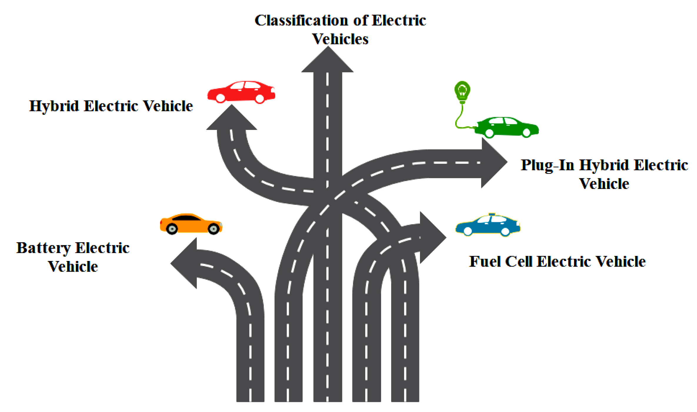
2. Categories of Electric Vehicles

Electric vehicles are propelled with electric motors and the energies are stored in a portable energy storage device such as a battery. It provides an efficient means for transportation and helps in reducing atmospheric pollution due to the emission of GHG. These electric vehicles are classified into different types, as shown in Figure 2.

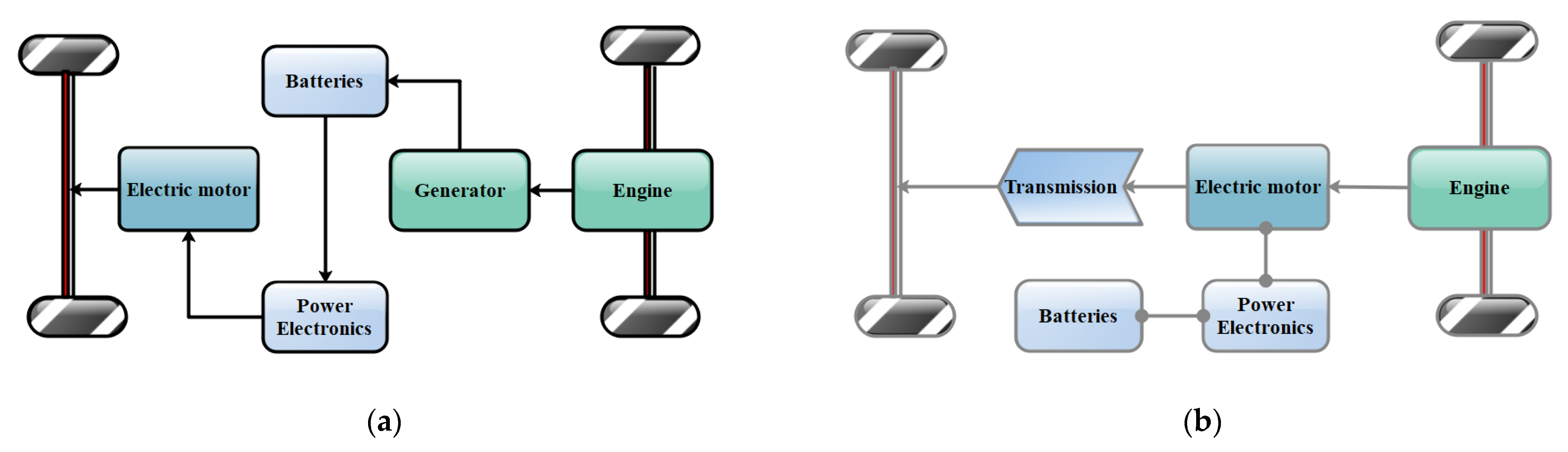
2.1. Hybrid Electric Vehicles (HEV)

This kind of electric vehicle is formed by the combination of two different power sources i.e., an engine and an electric motor [4]. The battery connected with the HEV system is charged by the electricity that is generated by the braking system. By using this model, fuel economization can be enhanced and thus supersedes the usage of internal combustion engines [5]. The pictorial representation of series and parallel hybrid electric vehicle drive trains is shown in Figure 3a,b, respectively.

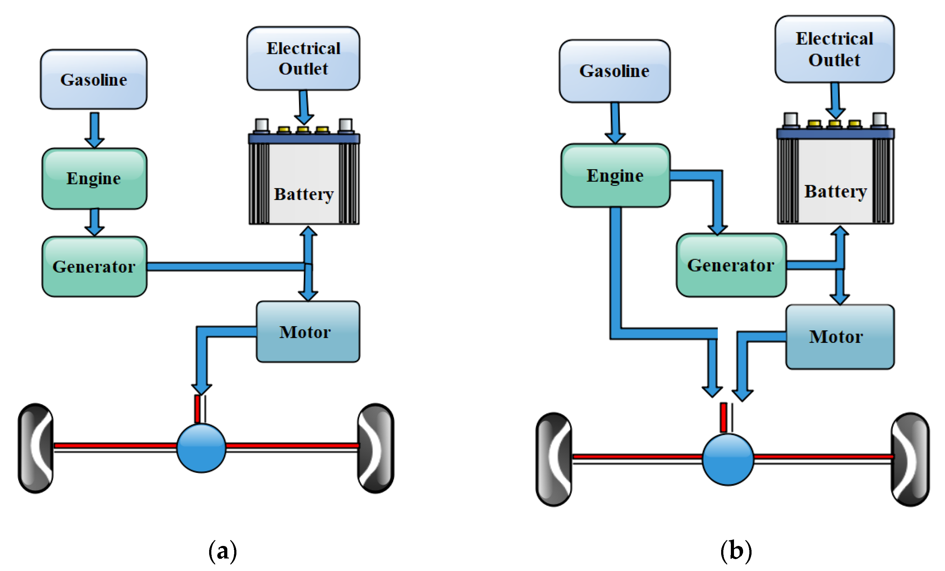
2.2. Plug-In Hybrid Electric Vehicle (PHEV)

The plug-in hybrid electric vehicle is similar to HEV, with electricity as the prime source and the engines used when the battery is depleted. The schematic of PHEV for series and the parallel connection is shown in Figure 4. One of the major advantages of PHEV is that it uses gasoline for driving vehicles. This makes it more flexible and popular among the EV sector [6]. The batteries employed in PHEV can be charged in two ways, either by using an external electric source or by the braking system. Some of the basic requirements of batteries for PHEV system are listed below [7].
  • It should have a high power density
  • It should have a high energy density
  • It should have the capability of recycling
  • It is advised to use the batteries with a long life cycle, provided with high safety measures.

2.3. Battery Electric Vehicles (BEV)

In BEVs, the vehicle is driven by an electric motor, and the energy is stored in batteries that are attached to the system. The block diagram of battery electric vehicles is given in Figure 5.
These vehicles can be charged by an external electric source and are therefore also called plug-in electric vehicles. Apart from the merits of BEVs, the major drawback of this kind of vehicle is the size of the battery. BEVs can be used only for short-distance transportation. For longer distances, the battery cost will be high and the system becomes complex [8].

2.4. Fuel Cell Electric Vehicle (FCEV)
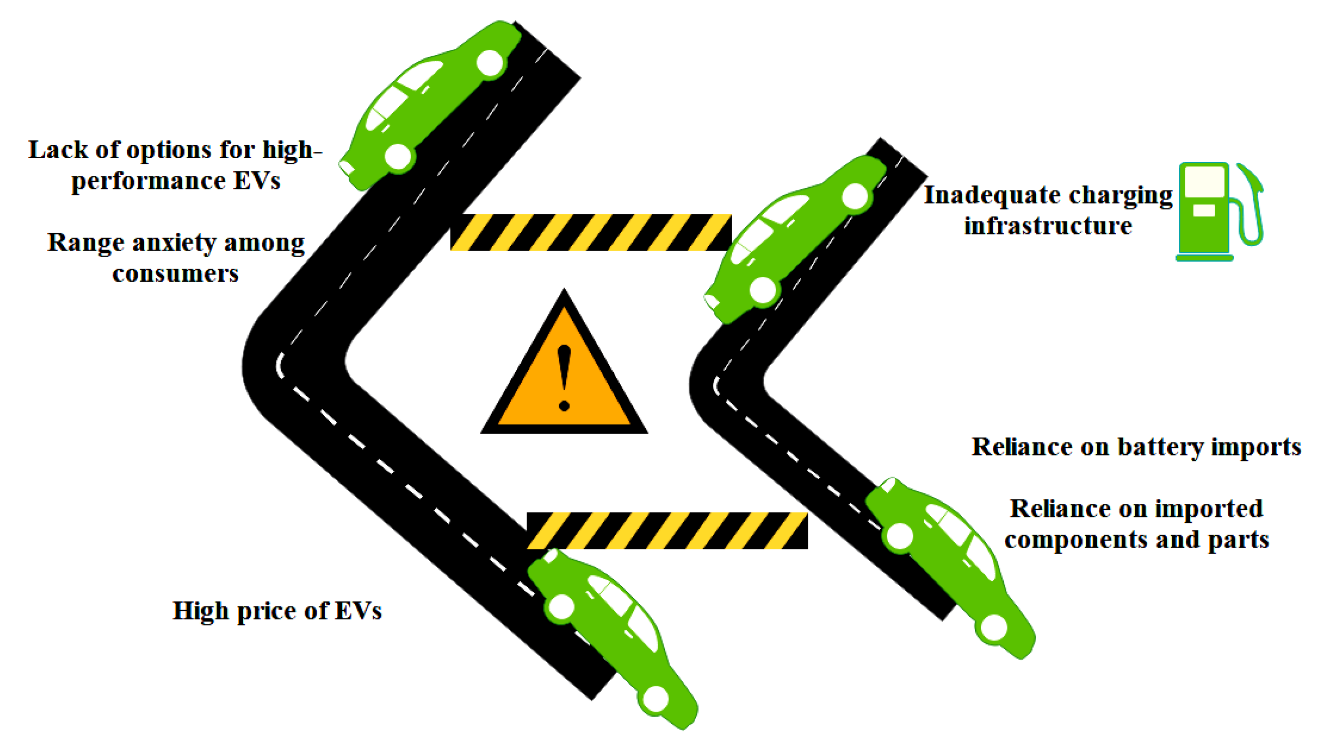
FCEVs are novel kind of EV that are driven by the electrical energy obtained from the hydrogen fuel from a fuel cell stack. These vehicles are emerging as a clean source of energy with high conversion efficiency. It possesses good dynamic properties with an efficient driving range. The drawbacks of internal combustion engine (ICE) vehicles, such as shortage in energy, pollution, etc., can be rectified with the help of FCEVs [9,10]. The drive train of FCEVs consists of a fuel cell stack, power battery bank, converter topology (DC-DC), and an electric drive system with the motor. A schematic of the FCEV system is shown in Figure 6.
The entireties of electric vehicle types are compared based on some parameters and listed in Table 1.

3. Challenges in EV

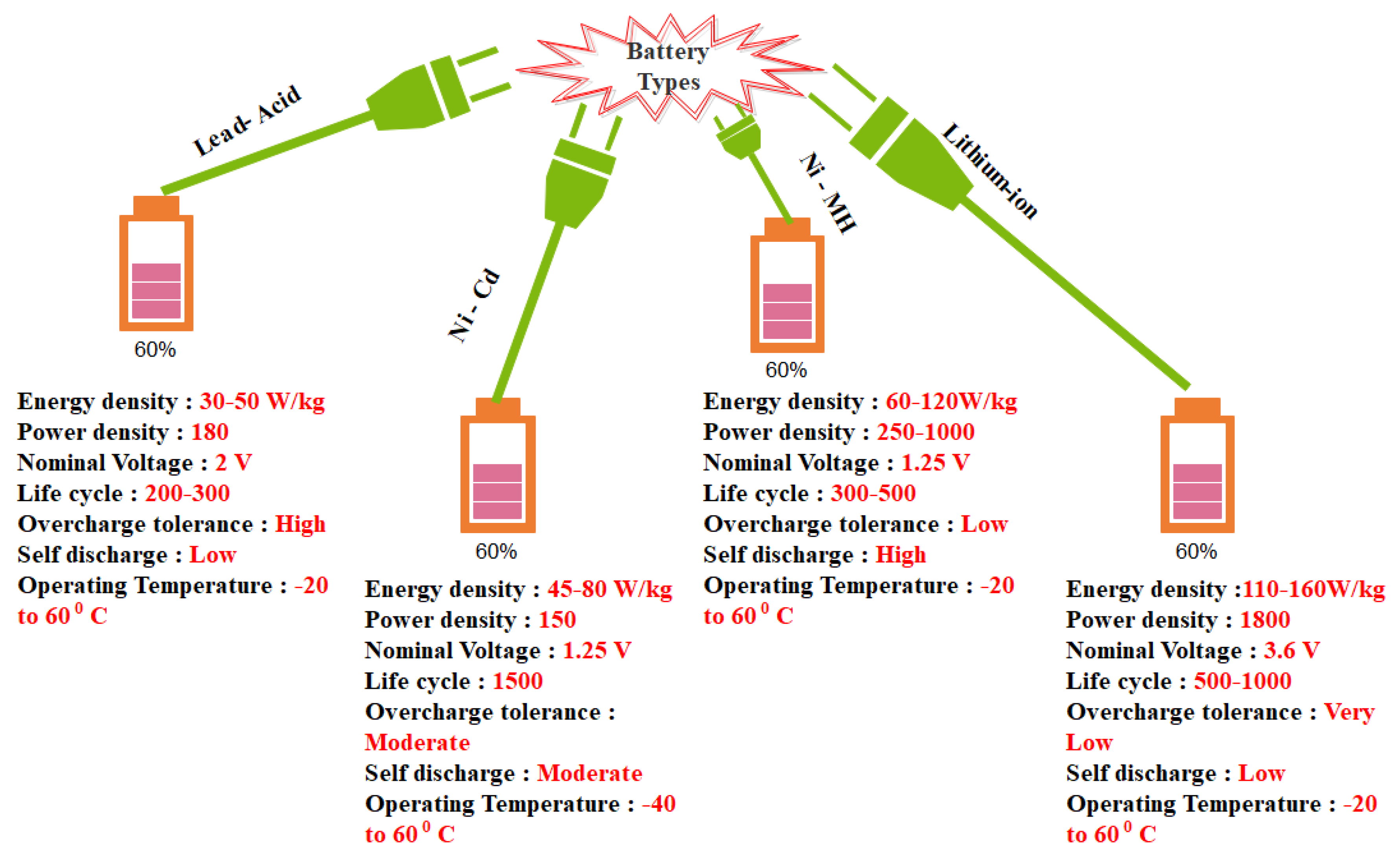
3.1. Battery Technology

Battery plays a vital role in the development of electric vehicles. It is one of the key parts of the vehicle drive train system for the efficient operation of EVs. The power rating, size, characteristics, and life cycle of the batteries are the few parameters that have to be noted while selecting a battery for an electric vehicle. The other important factor in the battery is the charging and discharging scheme. Generally, the level of charge in EVs refers to the voltage and power rating of the charging system [11,12]. The charging characteristics of the batteries are determined by the factors SOC, SOH, and DOD and they can be estimated by incorporating a battery management system (BMS) [13].
Researchers have analyzed and performed many experiments on battery technologies to improve the efficiency of the batteries incorporated in EVs. Some of the advanced batteries developed for EV which are light in weight, compact in size, and cost-effective are discussed below:
(i)
Lithium-ion battery: The lithium battery possesses high power and energy density. The charging and discharging capability of lithium-ion are fast when compared to other types of batteries. It has a longer life cycle [14].
(ii)
Lithium-sulfur battery: In this case, the anode is made up of lithium, and the cathode is made up of sulfur-carbon. Theoretically, it proves to be cost-effective than lithium-ion batteries but the life cycle of Lithium-sulfur batteries is low.
(iii)
Solid-state batteries: Solid-state batteries include a capacitor. The important features of solid-state batteries are as follows: capable of operating at higher temperature range, eliminates electrolyte leaks, extended lifecycle [15].
A diagram representing the characteristics and performance parameter of commonly used batteries for EVs is shown in Figure 7 [16].

3.2. Charging Infrastructure

Next to battery technology, the charging infrastructure for an electric vehicle is one of the most important factors. Generally, charging equipment includes different types of converters for power conversions from AC/DC, DC/DC, etc. The basic block diagram for an electric charger is shown in Figure 8.
The charging modes of PHEV and BEVs are classified into four types based on the charging station type [17]. A detailed view of the types of charging modes is given in Table 2 [18,19,20,21].

4. Standards for Electric Vehicles

The usage of electric chargers for EVs can be chosen based on the rating of the system with the help of some predefined standards. The different IEC and SAE standards related to electric vehicle equipment are given below:
IEC 62196: This standard defines about the plugs, socket outlets, vehicle inlets and couplers.
[22,23]
The various accessories required for the charging of an electric vehicle is included and explained in this standard. The operating voltage and current ratings of these devices should not exceed 690 V AC at 50 Hz and 250 A, respectively. In the case of DC voltage, it is restricted to 1500 V DC and 400 A. The installation of all these components should be done by a skilled person. These components can be used with the charging circuit explained in the standard IEC 61851.
IEC 61851: This standard defines the on-board and off-board equipment for charging electric vehicles.
[24]
The standard explains the services for providing additional power that are required by the electric vehicle whenever it is connected to a supply. The supply voltage ratings are limited to 690 V AC and 1000 V in the case of DC supply. It also suggests the electrical safety requirement of the devices which apply to this standard.
SAE J2293: This explains about the energy transfer system for Electric Vehicles.
[25]
It defines the requirements for energy transfer between the EV and the utility system. It applies to both onboard and Off-board electric vehicles to ensure the interoperability of the vehicles and supply system.
SAE J1772: This standard deals with the electric vehicle conductive charge coupler.
[26]
This standard is meant for the functional and operational requirements for the EV inlet and the connectors when operated under conductive charging mode.
SAE J1773: This standard deals with the electric vehicle inductively couple charging.
[27]
This explains the phenomenon of inductively coupled charging in electric vehicles for power transfer at a frequency that is greater than the power line frequency. It applies to inductive charging for the power transfer at Levels 1 and 2. The important point to be noted in this case is that this standard is only for manual connected mode and is not applicable for automatic connection methods.
SAE J2836: Recommended Practice for communication between Plug-In Vehicles and utility grid.
[28]
It includes the functional operations for plug-in electric vehicles, interoperability standards for the transfer of power from the utility to EV, and security measures. It also gives instructions for hybrid communication of vehicles, such as V2G connection employed with an off-board inverter.
NEC 625 USA: It defines about the Electric Vehicle Charging System.
The provisions of this article cover the electrical conductors and equipment external to an electric vehicle that connect an electric vehicle to a supply of electricity by conductive or inductive means, and the installation of equipment and devices related to electric vehicle charging.
CHAdeMO Japan: DC fast charging standard.
[29]
It defines the method of fast charging of battery-operated electric vehicles which can operate up to 1000 V DC with a current rating of 400 A. DC of high voltage rating is supplied through a specially designed electrical connector.
SS 428 08 34: Plugs and socket-outlets for household and similar purposes—Particular requirements for plugs and socket-outlets used in Sweden.
[30]
The safety measures for electric vehicle accessories such as plugs and socket-outlets have been given in detail. The voltage rating for the devices ranges between 50–1000 V AC and 75–1500 V DC. Other than the plugs and sockets, the instructions for general provisions of electrical equipment is explained in the National Electrical Safety Board regulation—2000:1.
SS-EN 61851-1: Electric vehicle conductive charging system—Part 1: General requirements.
The standard gives detailed instruction on the operating conditions of the electric vehicle along with its supply system and the interconnection of EV and its accessories. It also explains the safety measures of the supplied equipment with its voltage and current rating limited to 1000 V AC and 1500 V DC.
SS 436 40 00: Low-voltage electrical installations—Rules for design and erection of electrical installations.
[31]
It recommends the guidelines for the design, erection, and verification of electrical installations for low voltage. It also provides the safety measure for people and livestock against damages that could arise during the installation of such equipment and to ensure the proper functioning of the system.
SS-EN 60309-1: Plugs, socket-outlets and couplers for industrial purposes—Part 1: General requirements.
[32]
It applies to all electrical accessories which are operating under a voltage rating of 500 V and a current rating of 250 A at a frequency range of 500 Hz.
SS-EN 60309-2: Plugs, socket outlets and couplers for industrial purposes—Part 2: Dimensional interchangeability requirements for pin and contact-tube accessories.
[33]
The second part of this standard deals with the requirements of electrical accessories that can be employed for industrial usage. Here, the operating voltage is limited to 690 V at a frequency of 500 Hz. The current rating should not exceed 125 A. It cannot be implemented for those accessories which are meant to be used for domestic and general purposes.
SS-EN 62196-1: Plugs, socket-outlets, vehicle connectors and vehicle inlets—Conductive charging of electric vehicles—Part 1: General requirements.
[34]
It recommends the usage of plugs, sockets, and vehicle connectors for the conductive charging mode of EVs. The voltage rating of these devices should not exceed 690 V AC, 50 Hz, and the current rating restricted to 250 A. Similarly for DC, it should be maintained within 1500V DC at a rated current of 400 A. The later version of this standard describes the requirement which needs to be identified under the locking/interlock of the device and the latching device. It also gives instructions on insulated caps and proper testing methods.
SS-EN 62196-2: Plugs, socket-outlets, vehicle connectors and vehicle inlets—Conductive charging of electric vehicles—Part 2: Dimensional compatibility and interchangeability requirements for a.c. pin and contact-tube accessories.
[35]
It gives the requirements of electrical accessories with the additional dimensional compatibility and interchangeability for AC pins, connectors, and contact tubes. The ratings of these devices are limited to 480 V AC, 50 Hz with a current rating of 60 A.
SS-EN 62196-3: Plugs, socket-outlets, vehicle connectors and vehicle inlets—Conductive charging of electric vehicles—Part 3: Dimensional compatibility and interchangeability requirements for d.c. and a.c./d.c. pin and contact-tube vehicle couplers.
[36]
It defines the accessory requirements for AC and DC pins, connectors, and contact tubes for electric vehicles. For DC pins it can be maintained up to 1500 V DC, 250 A and for AC pins it should not exceed 1000 V, 250 A. This standard is applicable for interfacing the components at higher DC power.
SS-IEC 60884-1: Plugs and socket-outlets for household and similar purposes—Part 1: General requirements.
[37]
It can be applied to both fixed and portable devices with AC supply only. The voltage can be varied between 50–440 V AC with a current rating of 32 A.
SS-EN 50160: Voltage characteristics of electricity supplied by public distribution systems.
[38]
It describes the characteristics of voltage at the user’s terminal under normal operating conditions. It is not applicable for places such as construction work/maintenance with temporary supply.
SS-EN 61557-9: Electrical safety in low-voltage distribution systems up to 1 kV a.c. and 1,5 kV d.c.—Equipment for testing, measuring or monitoring of protective measures—Part 9: Equipment for insulation fault location in IT systems.
[39]
It recommends the requirements for equipment that can be incorporated at the insulation fault location system. In the case of unearthed IT ac systems, the nominal voltage rating is limited up to 1000 V and for DC systems it is up to 1500 V.
SS-EN 60529: Degrees of protection provided by enclosures (IP Code).
[40]
This standard applies to the classification of degrees of protection provided by enclosures for electrical equipment with a rated voltage not exceeding 72.5 kV.
SS-EN 61558-2-4: Safety of transformers, reactors, power supply units and similar products for supply voltages up to 1100 V—Part 2-4: Particular requirements and tests for isolating transformers and power supply units incorporating isolating transformers.
[41]
SS-EN ISO 15118-1:2019: Road vehicles—Vehicle to grid communication interface—Part 1: General information and use-case definition (ISO 15118-1:2019).
[42]
It is applicable for conductive and wireless power transfer technologies. The energy can be transferred either from the EV battery to the supply unit or vice versa. This ISO 15118 standard does not include the internal communication between the battery and other internal equipment of the vehicle.
SS-EN 61643-11: Low-voltage surge protective devices—Part 11: Surge protective devices connected to low-voltage power systems—Requirements and test methods.
[43]
Standard 61643-11:2011 deals with the specifications of the devices that are used for surge protection against the effects of lightning and other transient conditions. The frequency should be maintained at 50 Hz with the power circuits rated at 1000 V RMS.
SS-EN 62262: Degrees of protection provided by enclosures for electrical equipment against external mechanical impacts (IK code).
[44]
It refers to the degrees of protection provided by the enclosures against mechanical impacts whenever it is operated at a rating less than 72.5 kW.
SS-EN 60898-1: Circuit-breakers for overcurrent protection for household and similar installations—Part 1: Circuit-breakers for a.c. operation.
[45]
It is applicable for AC circuit breakers that operate at 50 Hz with a rated voltage of 440 V, 125 A. The short circuit current rating is limited up to 25,000 A. It can be used to protect over current against the households and wiring installations.
Apart from these standards, several other standards can be adopted for the interconnection of EVs. Researchers working in the electric vehicle domain have performed many experiments on the charging of EVs in distributed systems and their penetration levels. The EV acts as an active load element during the charging condition and acts as generators during the regeneration process [46,47].
Similarly, when a distributed generator like PV is connected to a power system network, certain standards and guidelines are recommended to ensure the compatible and reliable operation of the PV systems. As the penetration of PV gradually increases, its intermittent nature influences the operation of the power systems with voltage fluctuations and reverse power flow. To overcome this problem, suitable protective equipment can be added while interfacing with the grid [48]. The operational safety, signals indicating warning, insulation, access limitation, islanding protection, grounding, and other aspects form the crux of the guidelines while the standards are being framed, implemented, and revised.
Several standards are framed irrespective of the type of PV and the technologies from various manufacturers across the globe. The International Electrotechnical Commission (IEC) and Institute of Electrical and Electronics Engineers (IEEE) standards are widely used as a reference to develop other electric power standards [49,50]. Some of the major electric power standards applied towards PV interconnection for various countries and regions are shown in Figure 9.
Recently, solar-based EVs are also becoming more popular as they promotes the usage of renewable energy. Therefore, some of the above-mentioned standards can be utilized while interconnecting the solar-based EVs with the distributed systems. In that, the IEEE 1547 series explains the various standards such as the interconnection of distributed resources, testing procedures, monitoring, etc. The IEEE 1547 standards are given below in Table 3 [51].
In the IEEE 1547 standard, the general requirements and specifications for the interconnection of DERs with the electric power system (EPS) are mentioned. But this standard does not include any test procedures for evaluation and conformance testing of the equipment. Therefore, the IEEE has published another standard in the year 2005. In IEEE 1547.1 standard, the demonstration procedures for the interconnection of equipment, the specifications about the type of devices, and certain commissioning test procedures have been included. In 2008 another standard called IEEE 1547.2, was published which provides the guidelines for schematics, technical descriptions, and guidance on applications as a rule of thumb to ensure the proper usage of the 1547 standard. The guidelines on information exchange, monitoring, and control scheme of DER interconnections were explained in IEEE standard 1547.3. This helps to address proper communication and interoperability functions between the equipment and the operating personnel. The IEEE standard 1547.4 includes the guidelines on unintentional islanding, so that the power transfer from DERs to the adjacent electricity customers or the grid can be prevented when there is a sudden loss in power supply between the grid and the transmission system. It also addresses the capability for reconnection to a part of the grid while providing power to the nearby grid customers. In the year 2011, the IEEE standard 1547.6 was published to address the issues on the secondary networks of the distribution system. It also gives better solutions for the interconnection of distributed energy resources to the distribution networks. In 2013, IEEE framed a standard 1547.7 to address the scope, criteria, and impact of DER on the distribution system. It describes a scheme based on a tiered approach with certain criteria and also about the conventional impacts. These criteria are used for the determination of impact mitigation. In the final standard of the 1547 series, IEEE standard 1547.8 innovative process and operational procedures have been addressed and published in the year 2014. It includes some advanced control techniques for power electronic devices such as an inverter that can be used for grid support during the operation of the grid. All these standards can be utilized to ensure the proper operation of the grid and the devices associated with it.
Based on the IEEE and IEC standards, few other international standards are developed and being practiced for PV interconnection. Some of the international standards are given in Table 4 [52].

5. Supporting Standards Facilitating PV Interconnection

Apart from the above-mentioned standards, other standards that are associated with PV Solar interconnection helps in the integration of PV with the power system. Several other devices such as PV modules, data acquisition systems, smart grid interoperability, protection devices, and standards for balance of system (BOS) components like mounting structure, cables, batteries, junction boxes, switch gears, charge controllers are also discussed in this section.
(a)
PV solar module technology standards
PV solar modules are classified based on the type of material used. They are crystalline and thin-film solar modules. The United States adopts IEC 61215, IEC 61730-I &II, IEC 61701 for using crystalline technology. IEC 61646, IEC 61730-I&II, IEC 61701 are adopted for employing crystalline technology. Part I are the requirements for the construction of the module and part II are the requirements for testing and safety qualification. India adopts IEC 61215 (CEA)/IS 14286, IEC 61730—I & II (CEA), IEC 61701/IS 61701 (MNRE) for using the crystalline technology. IEC 61646 (MNRE), IEC 61730- I &II (CEA), IEC 61701/IS 61701 (MNRE) are adopted for the thin-film PV solar modules. Germany adopts IEC 61215, IEC 61730-I &II, IEC 61701 for using crystalline technology, and IEC 61646, IEC 61730-I&II, IEC 61701 for thin-film technology. Australia adopts IEC 61215, IEC 61730- I &II, AS/NZS 5033 using crystalline type PV. IEC 61646, IEC 61730-I & II, AS/NZS 5033 (installation and safety requirements of PV array) for thin-film technology [53].
(b)
Data acquisition systems
A suitable combination of computer software application and electronic hardware is required for extracting the information about the health of the power system network to which PV solar has been interconnected. The complete status of this PV solar could then be reported to a remote location. A data acquisition system could perform this task. This can be considered to be a subset of the supervisory control and data acquisition (SCADA) system. With the introduction of digital computers, command signals from the control center were issued to lower or raise the generation levels and the opening and closing of the circuit breakers based on suitable monitoring of the system status.
Following a disturbance at the generation and transmission level, the ability of the system to withstand such contingences defines the system’s security. Power system security is an important facet in monitoring, analysis, and real-time coordination of transmission and generation systems [54]. As the traditional power system becomes complex, the next-generation grid is commonly referred to as a smart grid. As a part of the planning and operation of the grid, during the high penetration of PV solar acquiring the data has become an important aspect. As the penetration becomes more significant, the role of data acquisition systems becomes necessary. In the USA, FERC Order 661-A contains SCADA requirements for wind plants. These are sometimes applied to large-scale PV plants. Further details on SCADA for power system application on SCADA for power system can be found in IEEE 1547.3 The complete guidelines for SCADA in power systems for monitoring, exchange of information, and the control of the distributed resources’ interconnection be found in IEEE 1547 standard.
IEC 61850 is the global standard that has been applied towards communication networks and systems for power utility automation functionalities. Australia adopts AS 4418.1 as a part of telecommunication systems and a protocol for SCADA systems. CEA in India does not mandate any such protocol using data acquisition systems like SCADA.
(c)
Communication standards
For the small PV power stations, there are no communication standards, but for medium and large-scale PV, there are standards that are adopted.
China has adopted GB/T 19964, Q/GDW 617, and GB/T29319. Tracking the irradiance, temperature and ambient temperature are part of this standard developed. Information about the parameters like voltage, frequency, active power, reactive power, power factor, main transformer, and disconnection status is also yielded. The communication standards for the U.S and Germany are based on the negotiations between the grid company and the party that generates power [55].
(d)
Interoperability—IEEE 2030 Standard
This standard provides guidelines in understanding and defining smart grid interoperability of the electric power system with end-use applications and loads. Interconnection and intra-facing frameworks and strategies with design definitions are addressed in this standard, guiding in expanding current knowledge. This expanded knowledge base is needed as a key element in grid architectural designs and operations to promote a more reliable and flexible electric power system. Interoperability is the “ability of two or more systems or components to exchange information and to use the information that has been exchanged.” The issues include the interoperation of system components supposedly conforming to a particular standard as well as the interoperation of components across standards. It is comprised of the interaction between different domains including the power systems, information technology, and communication architecture. Though the standard doesn’t exclusively address PV interconnection, it is embedded within this as a part of the smart grid. During the interconnection process, the information about the interaction of PV solar interconnection from the renewable energy domain with other different domains like communication systems and information technologies is evident.
(e)
Traditional Power System
A traditional/conventional power system infrastructure is distinctly made up of generation, transmission, and distribution systems. The flow of electricity in this setting is unidirectional, i.e., from the generation systems to the transmission systems and then to the distribution systems that would cater to the needs of a large number of customers. In other words, a traditional power system consists of centralized generation with mainly one-way communication, limited sensing, monitoring, and autonomous control.
(f)
Smart Grid Infrastructure
A smart grid can be defined in several ways. It can be referred to as a smart power system, an intelligent grid, the grid of the future, a self-healing grid, etc. A smart grid is the transformation of a traditional power system by incorporating distributed generation including renewable sources of energy like PV Solar and energy storage, intelligent power electronics, intelligent measurements, intelligent communications, computational intelligence, cybersecurity, visual and data analytics, and intelligent control systems. Unlike the traditional power systems, a smart grid allows reverse power flow that could also be referred to as a two-way flow of electricity with two-way communication providing system and customer flexibility A smart grid would no longer be defined in terms of N-1, N-2, or N-k, as in a traditional power system, but now in terms S-1, S-2, or S-k, where ‘S’ refers to a system of the systems. Currently, there are three additional complementary standards designed to expand upon the base 2030 standard. IEEE P2030.1, Guide for Electric-Sourced Transportation Infrastructure, IEEE P2030.2, Guide for the Interoperability of Energy Storage Systems Integrated with the Electric Power Infrastructure, and IEEE P2030.3, Standard for Test Procedures for Electric Energy Storage Equipment and Systems for Electric Power Systems Applications. The series of IEEE 1547, the IEEE Std 1547.4 (microgrids) addresses many of the technical integration issues for a mature smart grid, including issues of high penetration of distributed generators like PV Solar and electric storage systems, grid support, and load management. The smart grid interoperability standard is more of a layered approach. As the grid is evolving and expanding, the smart grid interoperability defines the PV interconnection as its interaction with other domains of engineering [56].
(g)
Protection Devices
During abnormal events like voltage fluctuations, frequency deviations and unintentional islanding can occur. To protect from further intensification of the events, protective devices are mandatory, and hence their standards are associated. Typical protection devices in solar systems consist of surge protective devices, DC and AC isolator switches, and an isolation transformer.
(h)
Surge Protection Devices
PV Solar is subjected to lightning strikes and surges at any unexpected instant of time that can lead to electrical/mechanical damages. Irrespective of the distance, even if the lightning strikes a few meters away, it will induce surge voltage in the electrical installation loops that will cause severe damage. The U.S adopts UL 1449. Standards DIN CLC/TS 50539-12 (VDE V 0675-39-12): 2010-09, prEN 50539-11, EN 61643-11 are adopted by Germany. Australia adopted AS/NZS 1768. India adopts relevant International Standards as mandated by CEA and MNRE [57].
(i)
Isolator Switch
Both DC and AC isolator switches are used in the PV and grid-connected systems. The AC switch is required to provide manual isolation during system installation or any subsequent maintenance whereas DC switches are connected with PV array to isolate it from the grid during installation. The U.S adopts UL 98 and UL 508. IEC 60364-7-7-12, DIN VDE 0100-712, IEC 60947-3 are standards adopted by Germany. Standards for Australia include AS/NZS 60898/IEC 60947. India adopts IEC 60947-I, II & III/IS 60947-I, II & III (MNRE) [58].
(j)
Isolation Transformer
For safety reasons, electrical equipment or devices are isolated from the main power source as a part of AC reasons while the transformer supplies AC power from the source to the device. They can be used to eliminate the noise produced by the sensitive devices and also provides galvanic isolation between the interconnected systems. The standards associated with PV interconnection for an isolation transformer are as follows. IEC 61558-2-6 is adopted by Germany. India adopts IEC 61727 (CEA). It has also been mandated by some SERC [59].
(k)
Balance of System (BOS) components
A solar PV balance of system refers to the components and equipment which move the DC energy generated by the solar panels. Using a suitable inverter, the DC power is converted into AC power. BOS includes mounting structure, cables, batteries, junction boxes, switch gears, charge controllers. Short descriptions of selective BOS components with their standards are presented in this section [60].
(l)
Junction box
A junction box is an enclosure where all PV strings of any PV array are electrically connected and where protection devices can be located, if necessary. It also serves as a protection device when a fault occurs in the DC circuit.
(m)
Battery
Off-grid systems employ batteries more compared to grid-tied systems. The types of batteries used mainly in PV systems are vented (flooded) and valve-regulated. This regulation applies to all batteries made of lead acid and nickel. The life of a battery could be determined using a comprehensive testing procedure. The battery is put through 150 cycles of discharging and charging, assuming that the daily discharge is in the range of 2–20%. The cycles are continued until the battery capacity has decreased to 80% of its rated capacity, which is considered as the end of the useful battery life.
(n)
Charge controller
There is more possibility that batteries get overcharged due to the high rate of current. Solar charge controllers are charge regulators, in other words, they are referred to as battery regulators. The basic functionality of a solar charge controller is to protect the battery bank from getting overcharged by acting as a current limiter. They also ensure the life span of the battery. A charge controller is typically integrated with the battery-based inverter. The IEC 62093 standard is the most widely used globally for the testing procedure for all BOS components of PV systems in natural environments [61].
(o)
PV module mounting system
This system serves in the best way for fixing the PV panels on building facades, roofs, or to the ground. It also enables retrofitting of PV panels on the ceiling or building structures.
(p)
Cables and connectors
Cables and connectors play a vital role in connecting modules of PV solar farms to the inverter. Though the electrical connections in a system are not noticeable, they do have an impact in terms of losses at the points of contact. To avoid such losses and accidents, cable connections with less contact resistance can be done with protection and durability. Table 5 presents the standards for BOS components for PV interconnection.

6. Conclusions

Electric vehicles have emerged as a tool for the energy and transportation sector which uses electricity as the prime source for the propulsion of vehicles. This proves to be clean energy transportation, with several benefits including reduced air pollution, reduced noise pollution, high reliability, compact design structure with a well-equipped control system. This paper discusses the different types of EVs and their performance. Along with this, the challenges in the EV sector are also explained in brief. For a better operation of EV for domestic and commercial use, it is necessary to follow certain international standards that are published and proved to be efficient. Some of the important standards to be followed in the design and manufacturing of EVs are also mentioned in this paper. Hence, it will serve as a good point of reference for those working in the EV domain. In addition, some of the important PV standards were discussed briefly.

Author Contributions

S.P.S. performed the review under the guidance and direction of S.S.R. and S.N. who devised the idea in collaboration with E.R.C. and T.S. All authors have contributed towards the review. All authors have read and agreed to the published version of the manuscript.

Funding

This research received no external funding.

Conflicts of Interest

The authors declare no conflict of interest.

References

  1. Khurana, A.; Kumar, V.V.R.; Sidhpuria, M. A Study on the Adoption of Electric Vehicles in India: The Mediating Role of Attitude. Vision 2020, 24, 23–34. [Google Scholar] [CrossRef]
  2. Lazzeroni, P.; Olivero, S.; Repetto, M.; Stirano, F.; Vallet, M. Optimal battery management for vehicle-to-home and vehicle-to-grid operations in a residential case study. Energy 2019, 175, 704–721. [Google Scholar] [CrossRef]
  3. International Energy Agency. 2016. Available online: https://www.iea.org/news/electric-vehicles-have-another-record-year-reaching-2-million-cars-in-2016 (accessed on 7 June 2017).
  4. Zakaria, H.; Hamid, M.; Abdellatif, E.L.M.; Imane, A. Recent Advancements and Developments for Electric Vehicle Technology. In Proceedings of the 2019 International Conference of Computer Science and Renewable Energies (ICCSRE), Agadir, Morocco, 22–24 July 2019; pp. 1–6. [Google Scholar]
  5. Hannan, M.A.; Azidin, F.A.; Mohamed, A. Hybrid electric vehicles and their challenges: A review. Renew. Sustain. Energy Rev. 2014, 29, 135–150. [Google Scholar] [CrossRef]
  6. Maheshwari, P.; Tambawala, Y.; Nunna Kumar, H.S.V.S.K.; Doolla, S. A review on plug-in electric vehicles charging: Standards and impact on distribution system. In Proceedings of the 2014 IEEE International Conference on Power Electronics, Drives and Energy Systems (PEDES), Mumbai, India, 16–19 December 2014. [Google Scholar]
  7. Dhameja, S. Electric Vehicle Battery Systems; Elsevier: Amsterdam, The Netherlands, 2002; ISBN 0750699167. [Google Scholar]
  8. Chan, C.C. An overview of power electronics in electric vehicles. EEE Trans. Ind. Electron. 1997, 44, 3–13. [Google Scholar] [CrossRef] [Green Version]
  9. Dominguez, E.; Leon, J.I.; Montero, C.; Marcos, D.; Rodriguez, M.; Bordons, C.; Ridao, M.A.; Fernandez, E.; Lopez, E.; Rosa, F. Practical implementation of an hybrid electric-fuel cell vehicle. In Proceedings of the 2009 35th Annual Conference of IEEE Industrial Electronics, Porto, Portugal, 3–5 November 2009; pp. 3828–3833. [Google Scholar]
  10. Hegazy, O.; Van Mierlo, J.; Lataire, P.; Coosemans, T.; Smenkens, J.; Monem, M.A.; Omar, N.; Van den Bossche, P. An evaluation study of current and future fuel cell hybrid electric vehicles powertrains. World Electr. Veh. J. 2013, 6, 464–475. [Google Scholar]
  11. Xu, Y.; Wang, Z.; Li, Y.; Xin, A. Research on the model of EV battery and charger. In Proceedings of the 2012 Power Engineering and Automation Conference, Wuhan, China, 18–20 September 2012; pp. 3–6. [Google Scholar]
  12. Dragomir, F.; Dragomir, O.E.; Oprea, A.; Olteanu, L.; Olariu, N.; Ursu, V. Simulation of lithium-ion batteries from a electric vehicle perspective. In Proceedings of the 2017 Electric Vehicles International Conference (EV), Bucharest, Romania, 5–6 October 2017; pp. 1–5. [Google Scholar]
  13. Bhatt, D.K.; El Darieby, M. An Assessment of Batteries form Battery Electric Vehicle Perspectives. In Proceedings of the 2018 IEEE International Conference on Smart Energy Grid Engineering (SEGE), Oshawa, ON, Canada, 12–15 August 2018; pp. 255–259. [Google Scholar]
  14. Shafiei, A.; Williamson, S.S. Plug-in hybrid electric vehicle charging: Current issues and future challenges. In Proceedings of the 2010 IEEE Vehicle Power and Propulsion Conference, Lille, France, 1–3 September 2010. [Google Scholar]
  15. Suciu, G.; Pasat, A. Challenges and opportunities for batteries of electric vehicles. In Proceedings of the 2017 10th International Symposium on Advanced Topics in Electrical Engineering (ATEE), Bucharest, Romania, 23–25 March 2017; pp. 113–117. [Google Scholar]
  16. Aifantis, K.E.; Hackney, S.A.; Kumar, R.V. High Energy Density Lithium Batteries, Materials, Engineering, Applications; Wiley-Vch Verlag GmbH & Co. KGaA: Weinheim, Germany, 2010. [Google Scholar]
  17. SS-EN 61851-1. Electric Vehicle Conductive Charging System—Part 1: General Requirements. In SEK Svensk Elstandard, 2nd ed.; Swedish Institute for Standards: Stockholm, Sweden, 2011. [Google Scholar]
  18. Kersten, A.; Kuder, M.; Thiringer, T. Hybrid Output Voltage Modulation (PWM-FSHE) for a Modular Battery System Based on a Cascaded H-Bridge Inverter for Electric Vehicles Reducing Drivetrain Losses and Current Ripple. Energies 2021, 14, 1424. [Google Scholar] [CrossRef]
  19. Vitols, K. Efficiency of LiFePO4 battery and charger with passive balancing. In Proceedings of the 2015 IEEE 3rd Workshop on Advances in Information, Electronic and Electrical Engineering (AIEEE), Riga, Latvia, 13–14 November 2015; pp. 1–4. [Google Scholar]
  20. Directive, E.U. 94/EU of the European Parliament and of the Council of 22 October 2014 on the deployment of alternative fuels infrastructure. Off. J. Eur. Union 2014, 307, 1–20. [Google Scholar]
  21. Haghbin, S. Design of a 300 kW Compact and Efficient Fast Charger Station Utilizing High-Power SiC Modules and Nanocrystalline Magnetic Materials. In Proceedings of the 2018 20th European Conference on Power Electronics and Applications (EPE’18 ECCE Europe), Riga, Latvia, 17–21 September 2018; pp. P.1–P.7. [Google Scholar]
  22. IEC 62196-1:2014. Standards for Plugs, Socket Outlets, Vehicle Inlets and Couplers—Part I. Available online: https://www.sis.se/api/document/preview/573019/ (accessed on 18 February 2016).
  23. IEC 62196-2:2016. Standards for Plugs, Socket Outlets, Vehicle Inlets and Couplers—Conductive Charging of Electric Vehicles —Part 2: Dimensional Compatibility and Interchangeability Requirements for a.c. pin and Contact-Tube Accessories. Available online: https://www.sis.se/api/document/preview/8018957/ (accessed on 18 February 2016).
  24. IEC 61851-1:2010. Electric Vehicle Conductive Charging System Part-I: General Requirements; IEC: Geneva, Switzerland, 2010. [Google Scholar]
  25. SAE J2293-/1-200807: Energy Transfer System for Electric Vehicles-Part-I: Functional Requirements and System Architectures. Available online: https://www.sae.org/standards/content/j2293/1_200807/ (accessed on 7 July 2008).
  26. SAE J1772. This Standard Deals with the Electric Vehicle Conductive Charge Coupler. Available online: https://www.sae.org/standards/content/j1772_199610/ (accessed on 13 October 2017).
  27. SAE J1773/201406: Electric Vehicle Inductively Couple Charging. Available online: https://www.sae.org/standards/content/j1773_200905/ (accessed on 5 June 2014).
  28. SAE J2836_1/201907: Use Cases for Communication between Plug-In Vehicles and Utility Grid. Available online: https://www.sae.org/standards/content/j2836/1_201907/ (accessed on 15 July 2019).
  29. Chademo. DC Fast Charging. Available online: https://en.wikipedia.org/wiki/CHAdeMO (accessed on 29 April 2021).
  30. SS 428 08 34. Plugs and Socket-Outlets for Household and Similar Purposes—Particular Requirements for plugs and socket-outlets used in Sweden. In SEK Svensk Elstandard, 1st ed.; Swedish Institute for Standards: Stockholm, Sweden, 2018. [Google Scholar]
  31. SS 436 40 00. Low-voltage electrical installations—Rules for design and erection of electrical installations. In SEK Svensk Elstandard, 3rd ed.; Swedish Institute for Standards: Stockholm, Sweden, 2017. [Google Scholar]
  32. SS-EN 60309-1. Plugs, socket-outlets and couplers for industrial purposes—Part 1: General requirements. In SEK Svensk Elstandard, 3rd ed.; Swedish Institute for Standards: Stockholm, Sweden, 1999. [Google Scholar]
  33. SS-EN 60309-2. Plugs, socket outlets and couplers for industrial purposes—Part 2: Dimensional interchangeability requirements for pin and contact-tube accessories. In SEK Svensk Elstandard, 3rd ed.; Swedish Institute for Standards: Kista, Sweden, 1999. [Google Scholar]
  34. SS-EN 62196-1. Plugs, socket-outlets, vehicle connectors and vehicle inlets—Conductive charging of electric vehicles—Part 1: General requirements. In SEK Svensk Elstandard, 3rd ed.; Swedish Institute for Standards: Stockholm, Sweden, 2015. [Google Scholar]
  35. SS-EN 62196-2. Plugs, socket-outlets, vehicle connectors and vehicle inlets—Conductive charging of electric vehicles—Part 2: Dimensional compatibility and interchangeability requirements for a.c. pin and contact-tube accessories. In SEK Svensk Elstandard, 2nd ed.; Swedish Institute for Standards: Stockholm, Sweden, 2017. [Google Scholar]
  36. SS-EN 62196-3. Plugs, socket-outlets, vehicle connectors and vehicle inlets—Conductive charging of electric vehicles—Part 3: Dimensional compatibility and interchangeability requirements for d.c. and a.c./d.c. pin and contact-tube vehicle couplers. In SEK Svensk Elstandard, 1st ed.; Swedish Institute for Standards: Stockholm, Sweden, 2015. [Google Scholar]
  37. SS-IEC 60884-1. Plugs and socket-outlets for household and similar purposes—Part 1: General requirements. In SEK Svensk Elstandard, 3rd ed.; Swedish Institute for Standards: Stockholm, Sweden, 2013. [Google Scholar]
  38. SS-EN 50160. Voltage characteristics of electricity supplied by public distribution systems. In SEK Svensk Elstandard, 3rd ed.; Swedish Institute for Standards: Stockholm, Sweden, 2008. [Google Scholar]
  39. SS-EN 61557-9. Electrical safety in low-voltage distribution systems up to 1 kV a.c. and 1,5 kV d.c.—Equipment for testing, measuring or monitoring of protective measures—Part 9: Equipment for insulation fault location in IT systems. In SEK Svensk Elstandard, 2nd ed.; Swedish Institute for Standards: Stockholm, Sweden, 2009. [Google Scholar]
  40. SS-EN 60529. Degrees of protection provided by enclosures (IP Code). In SEK Svensk Elstandard; Swedish Institute for Standards: Stockholm, Sweden, 2014. [Google Scholar]
  41. SS-EN 61558-2-4. Safety of transformers, reactors, power supply units and similar products for supply voltages up to 1100 V—Part 2—4: Particular requirements and tests for isolating transformers and power supply units incorporating isolating transformers. In SEK Svensk Elstandard, 2nd ed.; Swedish Institute for Standards: Stockholm, Sweden, 2009. [Google Scholar]
  42. SS-EN ISO 15118-1:2019. Road vehicles—Vehicle to grid communication interface—Part 1: General information and use-case definition (ISO 15118-1:2019). In SEK Svensk Elstandard, 2nd ed.; Swedish Institute for Standards: Stockholm, Sweden, 2019. [Google Scholar]
  43. SS-EN 61643-11. Low-voltage surge protective devices—Part 11: Surge protective devices connected to low-voltage power systems—Requirements and test methods. In SEK Svensk Elstandard, 2nd ed.; Swedish Institute for Standards: Stockholm, Sweden, 2013. [Google Scholar]
  44. SS-EN 62262. Degrees of protection provided by enclosures for electrical equipment against external mechanical impacts (IK code). In SEK Svensk Elstandard, 1st ed.; Swedish Institute for Standards: Stockholm, Sweden, 2008. [Google Scholar]
  45. SS-EN 60898-1. Circuit-breakers for overcurrent protection for household and similar installations—Part 1: Circuit-breakers for a.c. operation. In SEK Svensk Elstandard, 2nd ed.; Swedish Institute for Standards: Stockholm, Sweden, 2019. [Google Scholar]
  46. Shafiee, S.; Fotuhi-Firuzabad, M.; Rastegar, M. Investigating the impacts of plug-in hybrid electric vehicles on power distribution systems. IEEE Trans. Smart Grid 2013, 4, 1351–1360. [Google Scholar] [CrossRef]
  47. Zhang, P.; Qian, K.; Zhou, C.; Stewart, B.G.; Hepburn, D.M. A methodology for optimization of power systems demand due to electric vehicle charging load. IEEE Trans. Power Syst. 2012, 27, 1628–1636. [Google Scholar] [CrossRef]
  48. Kadir, A.F.A.; Khatib, T.; Elmenreich, W. Integrating photovoltaic systems in power system: Power quality impacts and optimal planning challenges. Int. J. Photoenergy 2014, 2014, 1–7. [Google Scholar] [CrossRef]
  49. Schwartfeger, L.; Santos-Martin, D. Review of distributed generation interconnection standards. In Proceedings of the EEA Conference & Exhibition 2014, Auckland, New Zealand, 18–20 June 2014. [Google Scholar]
  50. International Electrotechnical Commission. IEC 61727 ed2.0 Photovoltaic (PV) Systems—Characteristics of the Utility Interface; International Electrotechnical Commission: Geneva, Switzerland, 2004. [Google Scholar]
  51. IEEE Standards Association. IEEE 1547 Standard for Interconnecting Distributed Resources with Electric Power Systems; IEEE Standards Association: Piscataway, NJ, USA, 2003. [Google Scholar]
  52. Rangarajan, S.S.; Collins, E.R.; Fox, J.C.; Kothari, D.P. A survey on global PV interconnection standards. In Proceedings of the IEEE Power and Energy Conference at Illinois (PECI), Champaign, IL, USA, 23–24 February 2017; pp. 1–8. [Google Scholar]
  53. Wohlgemuth, J.H. Standards for pv modules and components—Recent developments and challenges. In Proceedings of the 27th Eur. Photovoltaic Solar Energy Conference and Exhibition, Frankfurt, Germany, 24–28 September 2012; pp. 2976–2980. [Google Scholar]
  54. Abdallah, M.; Elkeelany, O. A survey on data acquisition systems DAQ. Int. Conf. Comput. Eng. Sci. Inf. 2009, 240–243. [Google Scholar] [CrossRef]
  55. Li, R. Distributed Power Resources: Operation and Control of Connecting to the Grid; Elsevier: Amsterdam, The Netherlands, 2019. [Google Scholar]
  56. Basso, T. IEEE 1547 and 2030 Standards for distributed Energy Resources Interconnection and Interoperability with the Electricity Grid; National Renewable Energy Lab. (NREL): Golden, CO, USA, 2014. [Google Scholar]
  57. DD CLC/TS 50539-12:2010. Low Voltage Surge Protective Devices: Surge Protective Devices for Specific Application Including d.c. Available online: https://343lzp26ts7kiqip8biqf71a-wpengine.netdna-ssl.com/wp-content/uploads/DD-CLC-TS-50539-12-2010-Low-voltage-surge-protective-devices-Surge-protective-devices-for-specific-application-including-d.c.pdf (accessed on 12 March 2010).
  58. IEC 60364-7-712:2017. Low Voltage Electrical Installations-Part-7-712: Requirements for Special Installations. Available online: https://343lzp26ts7kiqip8biqf71a-wpengine.netdna-ssl.com/wp-content/uploads/IEC-60364-7-712-2017-Low-voltage-electrical-installations-Part-7-712-Requirements-for-special-installations-or-locations.pdf (accessed on 10 April 2017).
  59. IEC 61558-2-6:2009. Safety of Transformers, Reactors, Power Supply Units and Similar Products for Supply Voltages Up to 1 100 V—Part 2–6: Particular Requirements and Tests for Safety Isolating Transformers and Power Supply Units Incorporating Safety Isolating Transformers. Available online: https://standards.iteh.ai/catalog/standards/iec/c0db4842-f786-4033-b611-94be8dc3149d/iec-61558-2-6-2009 (accessed on 11 February 2009).
  60. Elshurafa, A.M.; Albardi, S.R.; Bigerna, S.; Bollino, C.A. Estimating the learning curve of solar PV balance–of–system for over 20 countries: Implications and policy recommendations. J. Clean. Prod. 2018, 196, 122–134. [Google Scholar] [CrossRef]
  61. EN 62093:2005. Balance-of-System Components for Photovoltaic Systems—Design Qualification Natural Environments. Available online: https://standards.iteh.ai/catalog/standards/clc/c5c1c57b-23aa-43f1-a8ef-dfe56d6bd993/en-62093-2005 (accessed on 18 May 2005).
Figure 1. Challenges of electric vehicles.
Wevj 12 00117 g001
Figure 2. Classification of electric vehicles.
Wevj 12 00117 g002
Figure 3. (a) Series HEV drive train (b) Parallel HEV drive train.
Wevj 12 00117 g003
Figure 4. (a) Series PHEV drive train (b) Parallel PHEV drive train.
Wevj 12 00117 g004
Figure 5. Battery electric vehicle drive train.
Wevj 12 00117 g005
Figure 6. Schematic of fuel cell vehicle.
Wevj 12 00117 g006
Figure 7. Characteristics of batteries used for EV.
Wevj 12 00117 g007
Figure 8. Block diagram of EV charger.
Wevj 12 00117 g008
Figure 9. Major electric power system standards towards PV interconnection.
Wevj 12 00117 g009
Table 1. Comparison of Electric Vehicles.
Types of EVsHEVPHEVBEVFCEV
PropellantElectric motor drive and internal combustion engineElectric motor drive andinternal combustion engineElectric motorElectric motor drives
Energy storage systemBattery, ultra capacitor, ICE generating unitBattery, ultra capacitor, ICE generating unitBattery, ultra capacitorFuel cells
Operating modesCharge (assisting)Charge (assisting) and mixed modeCharge (depleting)Charge (depleting)
Battery typeNiMHNiMH, Li-ionLi-ionLi-ion
Maximum speed (km/h)17016080–200100–160
Maximum distance covered (km)900–1200900 during hybrid
20–60 during electric mode
120–400100–600 km
Electricity Consumption (kwh/km)-0.2250.1750.13
CO2 emission (gCO2/km)109132882.7–20.9
Energy SourceElectric grid, gasolineElectric grid, gasolineElectric grid charging stationsHydrogen
CharacteristicsVery low emission,
long range.
Power can be obtained in two ways.
Recharged from external outlet,
driving for long distance with electric mode alone
No emissionsVery little or no emissions, high efficiency
DrawbacksBattery and engine size optimization,
complex energy management
Relatively expensive,
maintenance cost is high and it is complex.
Battery cost is high for large capacity range, charging time, lack of availability of charging stationsCost is high, lack of availability of fueling facilities, battery sizing
Table 2. Parameters and levels of charging modes.
Charging LevelsSupplyVoltage RatingCurrent RatingPower RatingConnectors Used Based on the Standards
Level ISingle Phase120 V AC16 A2 kWSAEJ1772, NEMA 5–15 connectors
Level IISingle Phase240 V AC12–80 A2.9–19.2 kWSAE J1772, IEC 62196, IEC 60309, IEC 62198-2 Mennekes & Scame connectors
Level IIIThree Phase400 V AC32–63 A22.1–43.7 kWIEC 60309, Magne charge, IEC 62198-2 Mennekes & Scame connectors
Level IVDC supply300–600 V DCUpto 400 AUpto 240 kWCombo of SAEJ1772 & CHAdeMO, IEC 62196 Mennekes Combo connectors
Table 3. IEEE standards for interconnection of DGs (PV and EV) with distributed systems.
StandardDescription
IEEE 1547–2003IEEE Standard for Interconnecting Distributed Resources with Electric Power Systems.
IEEE 1547.1–2005IEEE Standard Conformance Test Procedures for Equipment Interconnecting Distributed Resources with Electric Power Systems.
IEEE 1547.2–2008IEEE Application Guide for IEEE Std 1547, IEEE Standard for Interconnecting Distributed Resources with Electric Power Systems.
IEEE 1547.3–2007IEEE Guide for Monitoring, Information Exchange, and Control of Distributed Resources Interconnected with Electric Power Systems.
IEEE 1547.4–2011Guide for Design, Operation, and Integration of Distributed Resource Island Systems with Electric Power Systems.
IEEE 1547.6–2011Recommended Practice for Interconnecting Distributed Resources with Electric Power Systems Distribution Secondary Network.
IEEE P1547.7Guide to conduct Distribution Impact studies for Distributed Resource Interconnection.
IEEE P1547.8Recommended Practice for Establishing Methods and Procedures that Provide Supplemental Support/ancillary services for Implementation Strategies for expanded use of IEEE Std 1547.
Table 4. Various standards for PV and EV and its charging (applicable for DGs).
StandardsDescription
IEEE Standard 929-2000IEEE Recommended Practice for Utility Interface of DG systems up to 10 kW
IEEE Standard 1547-2004IEEE standards for interconnecting distributed resources with electric power systems laid the foundation for: UL 1741, inverters, converters, controllers, interconnection system equipment for use with distributed energy resources.
CSA 22.2 No. 107.1-01(R2011)General use power supplies.
CAN/CSA-C22.2.NO.257-06 (R2011)Interconnecting Inverter based micro-distributed resources to distribution systems.
CAN/CSA-C22.3. NO. 9-08Interconnection of distributed resources and electric supply systems.
IEC-TC8Grid integration of renewable energy generation
IEC-TC57Security standards for power system’s information infrastructure
TC 82Solar photovoltaic energy systems.
TC 22Equipments for electronic power conversion.
IEC 62109Safety of power converters for use in photovoltaic power systems—Part 1: General requirements & Part 2: Particular requirements for inverters.
IEC 62116Test procedure of islanding prevention measures for utility-interconnected photovoltaic inverters.
IEC/TR 61850-90-7Communication networks and systems for power utility automation—Part 90-7 Object models for power converters in distributed energy resources (DER) systems.
IEC 62477Safety requirements for power electronic converter systems and equipment—Part1: general & Part 2: Power electronic converters from 1000 V AC or 1500 V DC upto 35 kV AC.
IEC 62116Test procedure of islanding prevention measures for utility-interconnected Photovoltaic inverters.
IEC 61727Photovoltaic (PV) systems characteristics of the utility interface.
Table 5. BOS component standards for PV interconnection.
BOS ComponentU.SGermanyAustraliaIndia
Junction boxesIEC 60670, UL 50DINEN50548
(VDE 0126-5):2012-02
AS 1939IEC 529-IP54, IP 21 (MNRE)
BatteryIEC 61427IEC 61427, DINEN 61427AS 4086IEC 61427, IS 1651, IS 13369 or IS 15549 (MNRE)
Charge controllerUL 1741IEC 60068-2, IEC 62093/EN 62093:2005IEC 62093IEC60068-2, IEC 62093 (MNRE)
PV module mounting systemUL 2703NoneAS/NZS 1170.2None
Cables and connectorsUL62, UL758, EN50521VDE0285, VDE 276, EN 50521, VDE-AR-E-2283-4: 2011-10AS/NZS 5000.1, AS/NZS 3191, AS/NZS 3000IEC 60227/IS 694,
IEC 60502/IS 1554-I&II, IEC 60189, EN 50,521 (MNRE)
Publisher’s Note: MDPI stays neutral with regard to jurisdictional claims in published maps and institutional affiliations.

