
A Novel AHRS Inertial Sensor-Based Algorithm for Wheelchair Propulsion Performance Analysis


Abstract
:1. Introduction
2. Materials and Methods
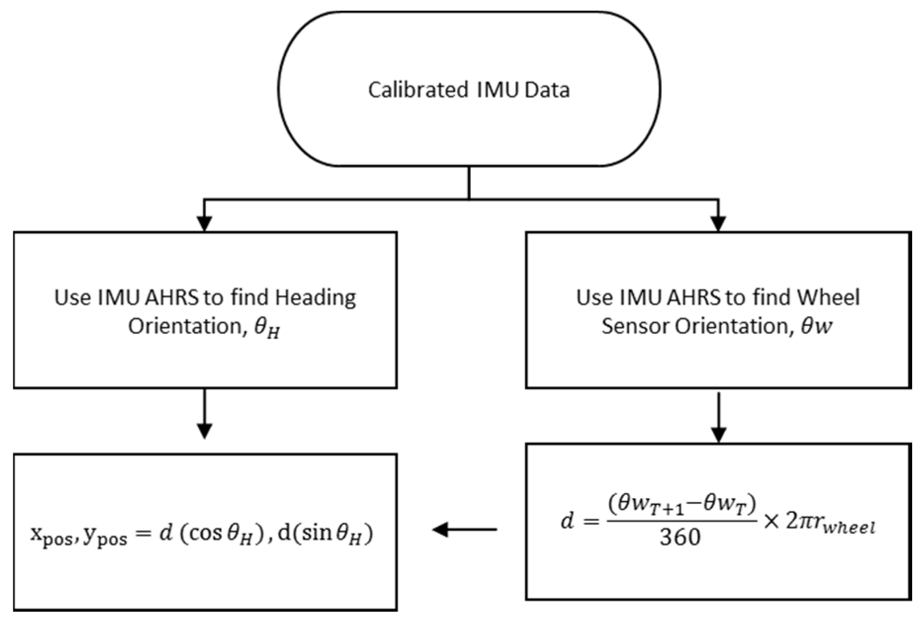
2.1. Algorithm
2.2. Validation
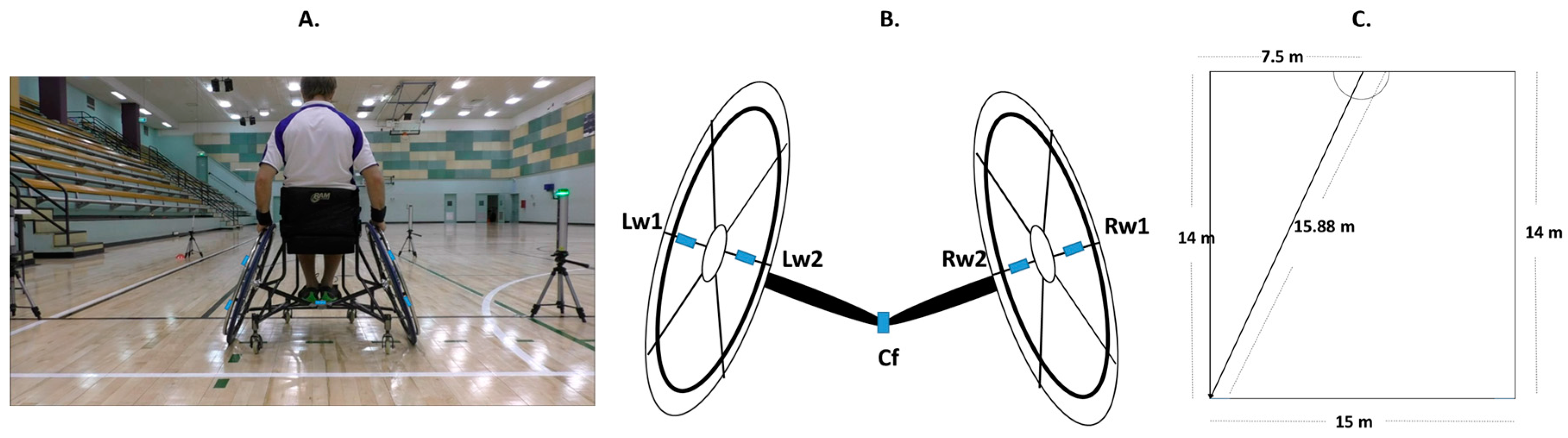
2.2.1. Methods
2.2.2. Trials
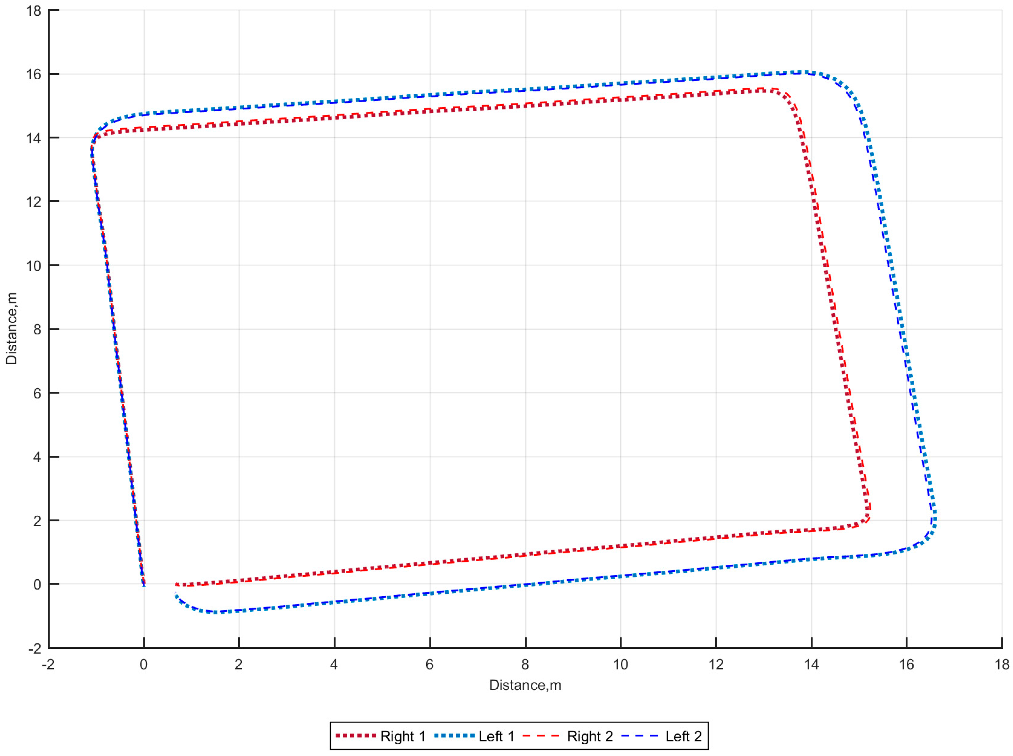
3. Results
4. Discussion
5. Conclusions
Acknowledgments
Author Contributions
Conflicts of Interest
References
- Goosey-Tolfrey, V.L.; Mason, B.; Burkett, B. The role of the velocometer as an innovative tool for Paralympic coaches to understand wheelchair sporting training and interventions to help optimise performance. Sports Technol. 2012, 5, 20–28. [Google Scholar] [CrossRef]
- Espinosa, H.G.; Lee, J.; James, D.A. The inertial sensor: A base platform for wider adoption in sports science applications. J. Fit. Res. 2015, 4, 13–20. [Google Scholar]
- Bergamini, E.; Morelli, F.; Marchetti, F.; Vannozzi, G.; Polidori, L.; Paradisi, F.; Traballesi, M.; Cappozzo, A.; Delussu, A.S. Wheelchair Propulsion Biomechanics in Junior Basketball Players: A Method for the Evaluation of the Efficacy of a Specific Training Program. Bio. Med. Res. Int. 2015, 2015. Article ID 275965. [Google Scholar] [CrossRef] [PubMed]
- Chua, J.J.C.; Fuss, F.K.; Subic, A. Evaluation of different gyroscope sensors for smart wheelchair applications. Procedia Eng. 2011, 13, 519–524. [Google Scholar] [CrossRef]
- Van der Slikke, R.M.A.; Berger, M.A.M.; Bregman, D.J.J.; Lagerberg, A.H.; Veeger, H.E.J. Opportunities for measuring wheelchair kinematics in match settings; reliability of a three inertial sensor configuration. J. Biomech. 2015, 48, 3398–3405. [Google Scholar] [CrossRef] [PubMed]
- Usma-Alvarez, C.C.; Chua, J.J.C.; Fuss, F.K.; Subic, A.; Burton, M. Advanced performance analysis of the Illinois agility test based on the tangential velocity and turning radius in wheelchair rugby athletes. Sports Technol. 2010, 3, 204–214. [Google Scholar] [CrossRef]
- Fuss, F.K.; Subic, A.; Chua, J.J.C. Analysis of wheelchair rugby accelerations with fractal dimensions. Procedia Eng. 2012, 34, 439–442. [Google Scholar] [CrossRef]
- Van der Slikke, R.M.A.; Berger, M.A.M.; Bregman, D.J.J.; Veeger, H.E.J. Wheel Skid Correction is a Prerequisite to Reliably Measure Wheelchair Sports Kinematics Based on Inertial Sensors. Procedia Eng. 2015, 112, 207–212. [Google Scholar] [CrossRef]
- Xu, H.; Chua, J.C.; Burton, M.; Zhang, K.; Fuss, F.K.; Subic, A. Development of low cost on-board velocity and position measurement system for wheelchair sports. Procedia Eng. 2010, 2, 3121–3126. [Google Scholar] [CrossRef]
- Chua, J.J.C.; Fuss, F.K.; Kulish, V.V.; Subic, A. Wheelchair rugby: Fast activity and performance analysis. Procedia Eng. 2010, 2, 3077–3082. [Google Scholar] [CrossRef]
- Pansiot, J.; Zhang, Z.; Lo, B.; Yang, G.Z. WISDOM: Wheelchair inertial sensors for displacement and orientation monitoring. Meas. Sci. Technol. 2011, 22, 105801. [Google Scholar] [CrossRef]
- Hiremath, S.V.; Ding, D.; Cooper, R.A. Development and evaluation of a gyroscope-based wheel rotation monitor for manual wheelchair users. J. Spinal Cord Med. 2013, 36, 347–356. [Google Scholar] [CrossRef] [PubMed]
- Ojeda, L.; Borenstein, J. Personal Dead-Reckoning System for GPS-Denied Environments. In Proceedings of the 2007 IEEE International Workshop on Safety, Security and Rescue Robotics, Rome, Italy, 27–29 September 2007; pp. 1–6.
- Madgwick, S.O.H.; Harrison, A.J.L.; Vaidyanathan, R. Estimation of IMU and MARG orientation using a gradient descent algorithm. In Proceedings of the 2011 IEEE International Conference on Rehabilitation Robotics (ICORR), Zurich, Switzerland, 29 June–1 July 2011; pp. 1–7.
- Mason, B.S.; Rhodes, J.M.; Goosey-Tolfrey, V.L. Validity and reliability of an inertial sensor for wheelchair court sports performance. J. Appl. Biomech. 2014, 30, 326–331. [Google Scholar] [CrossRef] [PubMed]
- James, D.A.; Wixted, A. ADAT: A Matlab toolbox for handling time series athlete performance data. Procedia Eng. 2011, 13, 451–456. [Google Scholar] [CrossRef]
- James, D.A.; Leadbetter, R.I.; Neeli, M.R.; Burkett, B.J.; Thiel, D.V.; Lee, J.B. An integrated swimming monitoring system for the biomechanical analysis of swimming strokes. Sports Technol. 2011, 4, 141–150. [Google Scholar] [CrossRef]
- Lai, A.; James, D.A.; Hayes, J.P.; Harvey, E.C. Semi-Automatic Calibration Technique using Six Inertial Frames of Reference; International Society for Optics and Photonics: Bellingham, WA, USA, 2004; pp. 531–542. [Google Scholar]
- Moore, J.; Hubbard, M.; Schwab, A.; Kooijman, J. Accurate measurement of bicycle parameters. In Proceedings of the Bicycle and Motorcycle Dynamics 2010, Symposium on the Dynamics and Control of Single Track Vehicles 2010, Delft, The Netherlands, 20–22 October 2010.


| Test | Laser | R1 | R2 | L1 | L2 | Mean | SD | % Error |
|---|---|---|---|---|---|---|---|---|
| 1 | 13.96 | 14.06 | 14.23 | 14.49 | 14.30 | 14.27 | 0.16 | 1.92 |
| 2 | 13.93 | 14.18 | 14.32 | 14.48 | 14.33 | 14.325 | 0.105 | 2.323 |
| 3 | 14.02 | 14.15 | 14.31 | 14.52 | 14.34 | 14.330 | 0.130 | 2.354 |
| 4 | 13.94 | 14.08 | 14.25 | 14.62 | 14.40 | 14.334 | 0.200 | 2.386 |
| 5 | 13.96 | 14.11 | 14.26 | 14.49 | 14.30 | 14.290 | 0.134 | 2.068 |
| Mean | 13.96 | 14.12 | 14.27 | 14.52 | 14.33 | - | - | - |
| SD | 0.03 | 0.04 | 0.04 | 0.05 | 0.03 | - | - | - |
| % Error | 0.28 | 0.81 | 1.90 | 3.57 | 2.33 | - | - | - |
| Test | Laser | R1 | R2 | L1 | L2 | Mean | SD | % Error |
|---|---|---|---|---|---|---|---|---|
| 1 | 15.87 | 16.04 | 16.03 | 16.51 | 16.37 | 16.24 | 0.21 | 2.23 |
| 2 | 15.87 | 16.04 | 16.13 | 16.54 | 16.42 | 16.28 | 0.21 | 2.51 |
| 3 | 15.82 | 16.07 | 16.09 | 16.45 | 16.32 | 16.23 | 0.16 | 2.20 |
| 4 | 15.91 | 16.12 | 16.21 | 16.73 | 16.58 | 16.41 | 0.25 | 3.32 |
| 5 | 15.85 | 16.13 | 16.22 | 16.45 | 16.33 | 16.28 | 0.12 | 2.52 |
| Mean | 15.86 | 16.08 | 16.14 | 16.53 | 16.40 | - | - | - |
| SD | 0.03 | 0.04 | 0.07 | 0.10 | 0.09 | - | - | - |
| % Error | 0.10 | 1.22 | 1.57 | 3.94 | 3.18 | - | - | - |
| Test | RWx | RWy | Error Distance (m) | LWx | LWy | Error Distance (m) |
|---|---|---|---|---|---|---|
| 1A * | −0.12 | 0.82 | 0.88 | 0.57 | 0.08 | 0.58 |
| 1B * | 0.54 | 0.41 | 0.68 | −0.22 | 0.65 | 0.69 |
| 2A * | 0.03 | 0.64 | 0.64 | −0.66 | 0.29 | 0.72 |
| 2B * | 0.01 | 0.68 | 0.68 | −0.28 | 0.67 | 0.72 |
| 3A * | −0.20 | 0.89 | 0.91 | −0.18 | 0.47 | 0.51 |
| 3B * | 0.47 | −0.77 | 0.91 | −0.35 | 0.47 | 0.59 |
| 1A ** | −0.13 | 0.61 | 0.62 | 0.09 | −0.99 | 1.00 |
| 1B ** | −0.09 | 0.56 | 0.56 | 1.03 | −0.14 | 1.04 |
| 2A ** | −0.15 | −0.55 | 0.57 | 0.44 | −0.02 | 0.44 |
| 2B ** | −0.24 | −0.48 | 0.53 | 0.13 | −0.54 | 0.56 |
| 3A ** | 0.05 | −0.64 | 0.64 | 1.02 | 0.38 | 1.08 |
| 3B ** | 0.04 | −0.65 | 0.65 | −0.12 | −0.90 | 0.91 |
| Test | RW1 | RW2 | % Error | LW1 | LW2 | % Error |
|---|---|---|---|---|---|---|
| 1 * | 56.73 | 57.88 | 1.86 | 61.59 | 61.12 | −0.60 |
| 2 * | 56.72 | 57.07 | 1.13 | 61.03 | 60.75 | −1.35 |
| 3 * | 56.56 | 58.84 | 2.56 | 61.54 | 61.09 | −0.67 |
| 1 ** | 59.93 | 60.34 | −2.58 | 58.14 | 57.82 | 3.05 |
| 2 ** | 60.45 | 60.80 | −1.78 | 57.19 | 57.06 | 1.53 |
| 3 ** | 60.57 | 60.97 | −1.56 | 56.60 | 56.63 | 0.64 |
© 2016 by the authors; licensee MDPI, Basel, Switzerland. This article is an open access article distributed under the terms and conditions of the Creative Commons Attribution (CC-BY) license (http://creativecommons.org/licenses/by/4.0/).
Share and Cite
Shepherd, J.B.; Wada, T.; Rowlands, D.; James, D.A. A Novel AHRS Inertial Sensor-Based Algorithm for Wheelchair Propulsion Performance Analysis. Algorithms 2016, 9, 55. https://doi.org/10.3390/a9030055
Shepherd JB, Wada T, Rowlands D, James DA. A Novel AHRS Inertial Sensor-Based Algorithm for Wheelchair Propulsion Performance Analysis. Algorithms. 2016; 9(3):55. https://doi.org/10.3390/a9030055
Chicago/Turabian StyleShepherd, Jonathan Bruce, Tomohito Wada, David Rowlands, and Daniel Arthur James. 2016. "A Novel AHRS Inertial Sensor-Based Algorithm for Wheelchair Propulsion Performance Analysis" Algorithms 9, no. 3: 55. https://doi.org/10.3390/a9030055
APA StyleShepherd, J. B., Wada, T., Rowlands, D., & James, D. A. (2016). A Novel AHRS Inertial Sensor-Based Algorithm for Wheelchair Propulsion Performance Analysis. Algorithms, 9(3), 55. https://doi.org/10.3390/a9030055