Review

Review of Recent Advances in the Application of the Wavelet Transform to Diagnose Cracked Rotors

Maqlab Group, Mechanical Engineering Department, University Carlos III of Madrid, Av. de la Universidad, 30, Leganés, Madrid 28911, Spain
*
Author to whom correspondence should be addressed.
Algorithms 2016, 9(1), 19; https://doi.org/10.3390/a9010019
Submission received: 9 January 2016 / Revised: 2 March 2016 / Accepted: 8 March 2016 / Published: 14 March 2016

Abstract

:
Wavelet transform (WT) has been used in the diagnosis of cracked rotors since the 1990s. At present, WT is one of the most commonly used tools to treat signals in several fields. Understandably, this has been an area of extensive scientific research, which is why this paper aims to summarize briefly the major advances in the field since 2008. The present review considers advances in the use and application of WT, the selection of the parameters used, and the key achievements in using WT for crack diagnosis.

1. Introduction

The detection of cracks in rotors is a vitally important area of maintenance as failure to recognize cracks can lead to catastrophic mechanical failure. The dynamic behaviour of cracked rotors has been studied since the 1960s, and since then advances have allowed for the detection and recognition of cracks before breaking occurs. However, there remain some cases, where crack detection occurs late, when the situation has become critical and catastrophic failure is imminent. Therefore, it is important to focus research on improving existing crack detection techniques by using knowledge about the dynamical behavior of these systems. Studies which focus on cracked rotors have been carried out using a variety of different methods in order to select patterns able to detect fault conditions.
This has become such a pressing issue that in 2008, the journal “Mechanical Systems and Signal Processing” published a special issue focusing solely on cracked rotors. Bachschmid and Pennacchi [1] highlighted that despite the high number of papers published about the dynamics of cracked rotors, these papers do not present experimental results, making it difficult to translate the results obtained to real systems. It is often the case that these studies do not focus on the inverse process of crack identification. Sekhar [2] stated that most of the studies dealt with a single crack, however, the problem of crack sizing and locating becomes more complex. A review of crack identification in rotating shafts by Papadopoulos [3], concluded that most of the work in crack detection was based on using vibration signatures. Papadopoulos classified diagnosis techniques as applying either model-based or vibration methods.
Model-based methods consider aim to produce identical effects to those seen in real life by using equivalent loading at the place of the crack. Usually these models are based on information extracted from directly measured signals, signal models, and process models, as demonstrated by in [4,5,6]. Vibration methods are based on detecting variations in the response, which are then assigned to a crack. Signals analyzed via vibration methods can come from real systems or models, as in the cases of [7,8], respectively. Models are mainly based on the crack breathing mechanism; further detail regarding this can be found in [9], and new breathing functions were proposed in [10]. The most commonly used model in this field is the simple Jeffcott rotor model, detailed in [11,12]. The Finite Elements Approach (FEA) has attracted researchers as an investigative tool for the study of crack breathing phenomena. However, traditional FEA has some limitations, such as low efficiency and accuracy, slow convergence, and strong nonlinearity. Wavelet spaces have also been employed, and from this wavelet finite element methods (WFEM) have been developed [13]. When comparing numerical results obtained using this model with experimental data, it is not only possible to detect the crack, but also the location and depth of that crack. These models have been applied to experimental results in works as demonstrated by [14], where it was combined with Genetic Algorithms (GA). Other examples of the WFEM model have been presented in [15,16].
Signals obtained from studying rotating machinery have complex structures and are comprised of a large amount of information. The aim of condition monitoring is to select the proper processing to extract the optimal features of a signal for fault detection. The features must fit two main requirements: they must be easy to handle with a low computational cost, and they must contain valuable information about the fault to be predicted. Within vibration methods, there is a large range of different signal processing methods that can be applied for this purpose. Short Time Fourier Transform (STFT) and Hilbert transform (HT) have traditionally been used to observe changes in response or in eigenfrequencies when a crack forms and propagates [17,18]. In 2004, Sabnavis et al. [19] affirmed that, for cracks, 1x and 2x frequency components using Fast Fourier Transform (FFT) and HT experiment very important changes at the steady state when a crack forms. However, in practice, these changes are very difficult to detect due to the presence of noise and other interfering factors. In recent years, new techniques classified by Sabnavis et al. [19], which they termed `non-traditional methods’, have appeared. The non-traditional techniques that have emerged work in both the time and frequency domains. Specifically, the Hilbert-Huang Transform (HHT), based on the Empirical Mode Decomposition (EMD) for obtaining the Intrinsic Mode Functions (IMFs), has been used effectively in the diagnosis of cracked rotors. This approach was detailed in [20,21]. However, due to its effectiveness in treating non-stationary signals, the most widely used technique in crack diagnosis in rotors is the Wavelet Transform (WT). Nowadays, WT is the most common technique used to treat signals [22].
WT theory has also been applied to acoustic emission (AE) signals to detect crack growth, as demonstrated in [23]. Recently, AE signals have been widely used in order to monitor the condition of rotating machinery. When the sensor is close to the source, AE is capable of detecting crack growth [24]. Typical frequencies associated with activity of AE range from 20 kHz to 1 MHz.
A review of the use of WT in the diagnosis of faults in machinery was presented by Peng and Chu [25] in 2004. They stated that the use of WT had not yet achieved precedent. The main reason for this is that the wavelet application is not a straightforward issue due to the requirement to select the wavelet function and the range scale, and also due to the fact that there are no standardized or generalized methods to carry out these requirements. Another drawback of using WT is the difficulty in understanding the results obtained.
The aim of the present review is to summarize the advances that have been achieved since 2008 in the application of WT to diagnose cracked rotors.

2. The Wavelet Transform

WT is a modern mathematical development for the treatment of signals both the time and frequency domains. Therefore it is specially useful in observing the changes in patterns over time. The Fourier Transform, and most techniques derived from it, are inappropriate to treat non-stationary signals due to the absence of any temporary information. A technique that is suitable for treating non-stationary signals is STFT. However, the major disadvantage for this technique is the resolution of the frequency obtained, which remains constant for the whole signal as the same window is applied. On the other hand, WT allows a high frequency resolution at low frequencies, and high time resolution at high frequencies, as desired.
The first concept of wavelets was set up by Morlet in 1984. Later, Meyer, Mallat, and Daubechies contributed with important developments regarding orthogonal wavelet functions. However, the use of WT became popular in engineering applications since the end of the 1980s, when Mallat [26] found that there was a relationship between Quadrature Mirror Filters and orthonormal wavelet functions. From this, new techniques allowed for the application of WT to a signal using recursive-filtering banks. Recently, WT has become the most widely applied tool in signal processing in many different fields such as voice recognition [27,28], noise reduction [29,30], electrocardiographs [31], and radio-frequency interference mitigation [32], amongst others.
Specifically in the field of fault detection, WT has been widely applied with the purpose of detect faults in shafts [33], bearings [34,35,36], gears [37,38,39] and beams [2,40].

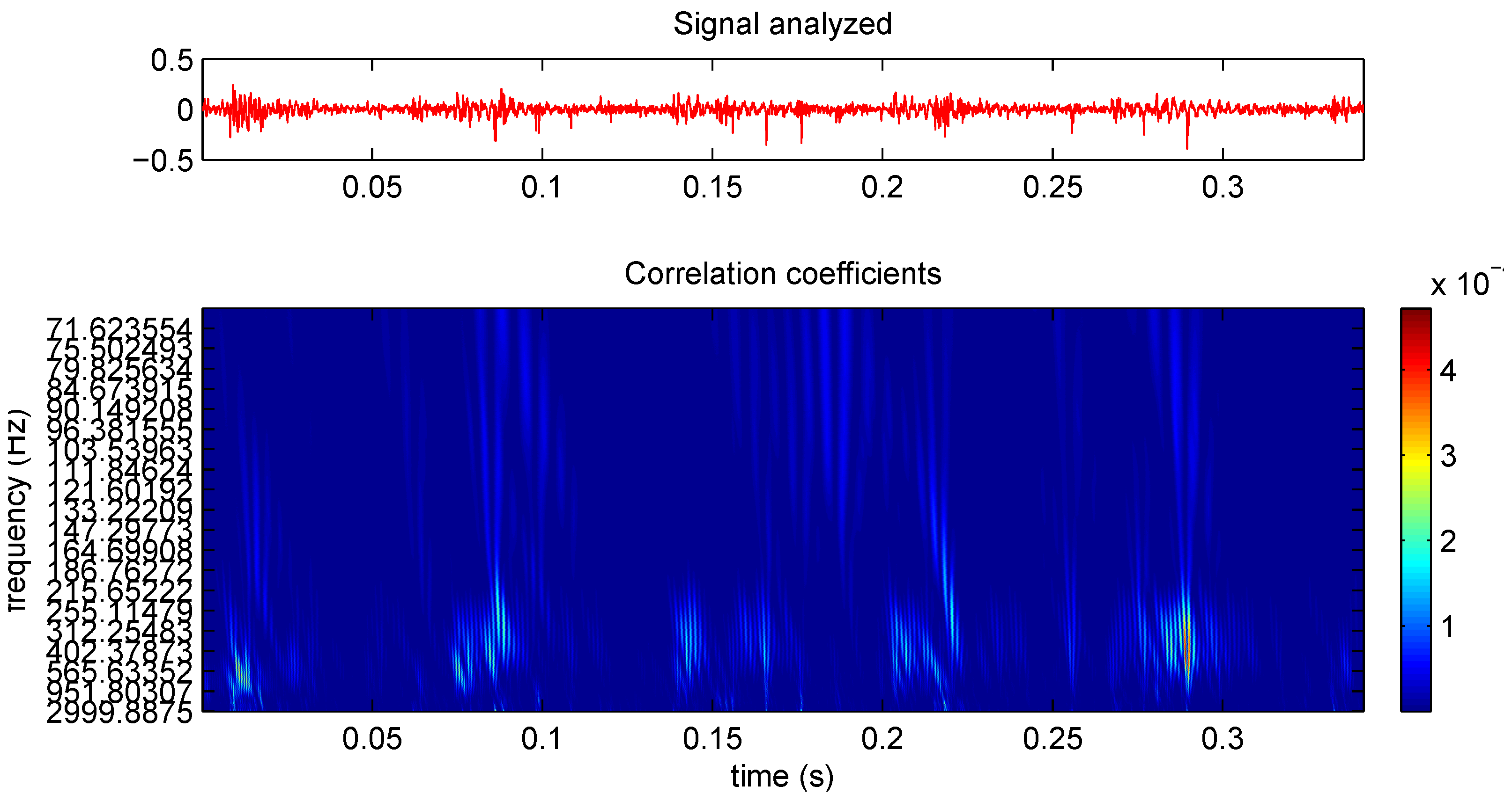
2.1. Continuous Wavelet Transform

The same way Fourier Transform (FT) obtains correlation coefficients between the analyzed signal and a sinusoidal one, WT obtains correlation coefficients between the signal and an orthonormal function, called the wavelet function, depending on the scale and position of the wavelet function. There are a lot of different types of wavelet functions, such as those detailed by Daubechies, Coiflet, Symlet, Morlet, and Meyer.
The Continuous Wavelet Transform (CWT) allows analysis of a signal through the correlation coefficients of that signals instead of using the whole signal information . The mathematical formula for determining CWT is shown in Equation (1):
C W T ( c , b ; ψ ) = w x ( t ) ψ * ( t b c ) d t
where x ( t ) is the signal in the time domain, ψ is the wavelet function, and w is a weighting function. The parameter c is related to the scale, and b is related to the position of the wavelet function. C W T ( c , b ; ψ ) represents the resulting coefficients, as a function of c, b and the wavelet function ψ.
Figure 1 shows a signal in the time domain and the corresponding CWT.
CWT is one of the best tools available to detect singularities of a signal. Singularity detection is carried out with the local maxima lines [25].
Regarding crack detection, Nagaraju et al. [41] affirmed that the presence of sub-critical (1/3 and 1/2 of the critical speed) components in the CWT may be indicative of cracking, although this may not always be reliable due to the high sensitivity to noise. They proposed an alternative technique, involving the calculation of the phase angle between the two signals (cracked and un-cracked) of two transverse vibration. The phase angle can be calculated with the Cross Wavelet Transform (XWT), called as they proposed.
The sub-critical 1/3 and 1/2 components calculated with CWT have also been used as indicators of the of a crack [42]. The amplitude values of sub-critical and critical peaks in the CWT are used to feed an Artificial Neural Network (ANN) [43], allowing crack diagnosis, and determination of the position and depth of the crack.
CWT has also been applied to diagnose notched rotors (i.e., rotors with a transverse open crack) [44], where it has been demonstrated that both CWT and changes on the 2× harmonic can be used as robust indicators.
Srinivas et al. [45] used the CWT coefficients as the input for an ANN. They studied the ability of the system to detect combined faults of unbalance and shaft crack. This method was tested successfully with a hit rate of 99.9%.
CWT has been used in engineering applications for fault detection of rotating machinery in the form of a scalogram. The scalogram is defined as the square of the modulus of the CWT. However, the use of CWT in current applications, to diagnose machinery faults, is still relatively rare. This is due to the fact that the visual interpretation of wavelet results is often difficult. Efforts have been made to extract the best features analyzing the residual wavelet scalogram [46].

2.2. Discrete Wavelet Transform

The initial application of the Discrete Wavelet Transform (DWT) was to use discrete data as the scale parameter, c, in the Equation (1). Commonly, the dyadic grid was used, resulting in c = 2 k . After Mallat’s developments [26], many derivations of the DWT appeared. These were based on the use of digital filters to optimize the computational process, generating information in frequency bands. This tool consists of the processing of a discrete signal, x ( i ) , at different positions and scales (i.e., different frequencies and resolution levels), decomposing the signals in approximation (A) and detail (D). The approximation information is obtained by means of a low pass filter, and the detail information using a high pass filter, as it can be observed in Figure 2.
After applying filters to a signal, S, of a frequency band [ 0 , π ] and number of samples, N, the frequency band is halved obtaining both approximation information (A) [ 0 , π / 2 ] and detail information (D) [ π / 2 , π ] . Therefore, applying the Nyquist rule [47], downsampling by two can be justified without losing any relevant information; this gives a resulting number of N / 2 samples [48].
The recursive application of the filtering algorithm resulted in Multiresolution Analysis (MRA) and the Wavelet Packet Transform (WPT).
The main application of this tools was in crack detection in the feature extraction. The DWT can represent a signal with a limited number of coefficients that can be directly used as features. Statistical parameters, and the energy of the coefficients, can also be used as features. The features selected can be all from the same decomposition level in the tree, this is called the single-level basis selection. Alternatively, the features can be selected from different levels, this is termed the multiple-level basis selection. The main problem when using these kind of transforms is in finding the best features for crack detection. In addition, the decision as to whether a defect does or does not exist requires a classification system. Using thresholding methods or intelligent classification systems, such as ANN, GA, or Support Vector Machines (SVM) is common.

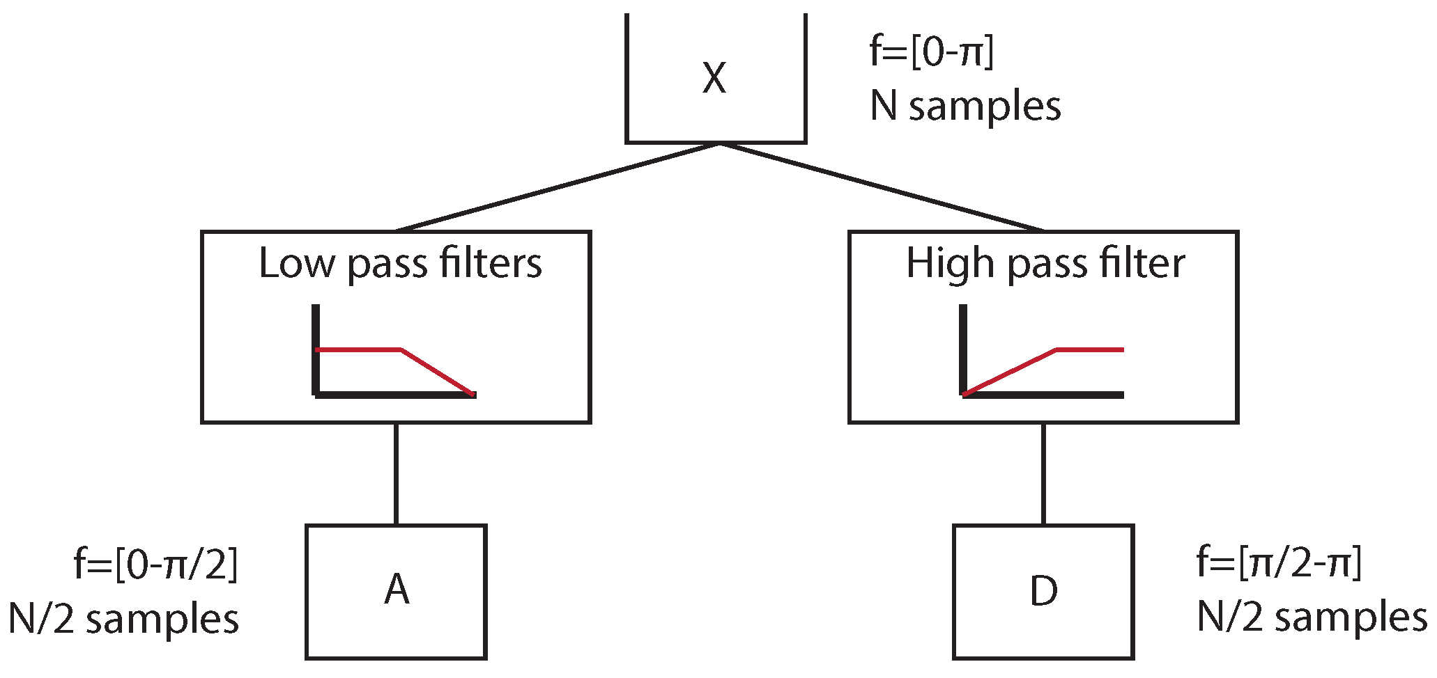
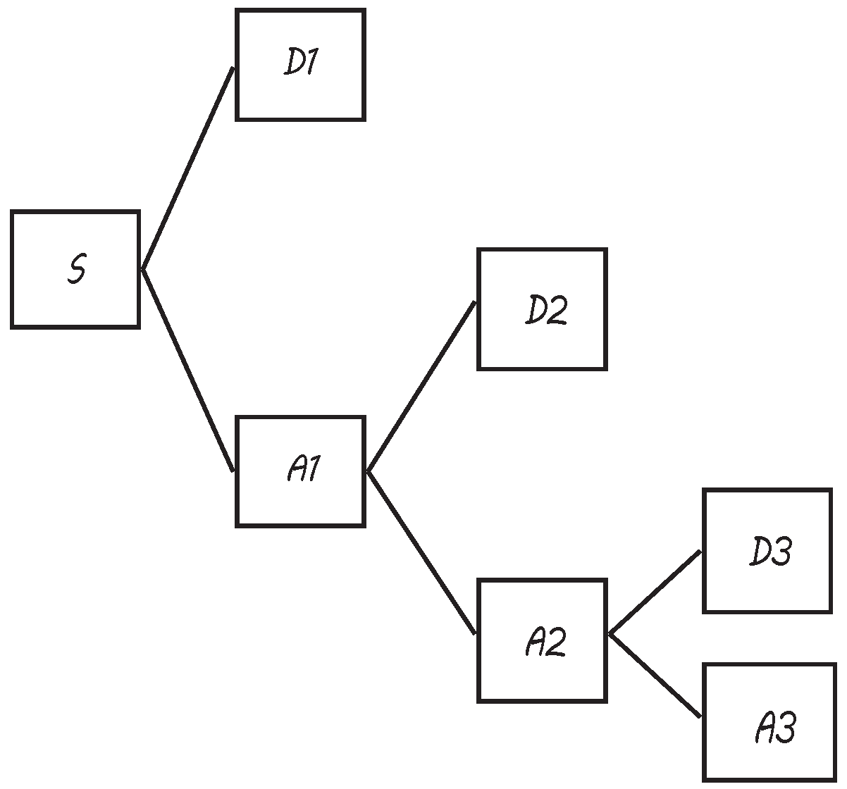
2.2.1. Multiresolution Analysis

The concept of MRA was developed by Meyer and Mallat in 1986. MRA consists on the application of the DWT in a recursive way until the desired decomposition level is reached. Initially, the main disadvantage of MRA is that only approximation information could be decomposed in the different frequency bands, as shown in Figure 3.
Sawicki et al. [49], applied MRA for a transverse crack detection using signals from an experimental set-up, using the RMS of the coefficients of the lower frequency bands.
MRA has been used for crack detection with very good results for signals obtained from a Jeffcott rotor model combined with neural networks [50].
MRA has been also applied to detect cracks growing in shafts using AE [23]. Specifically, envelope analysis combined with MRA has been applied with very good results. In [51], a comparison between vibration and AE signature was carried out. Using vibration signals, after MRA decomposition, diagnostic characteristics are observed. In the case of AE, envelope analysis was performed after wavelet decomposition, which allowed diagnostic information to become available.

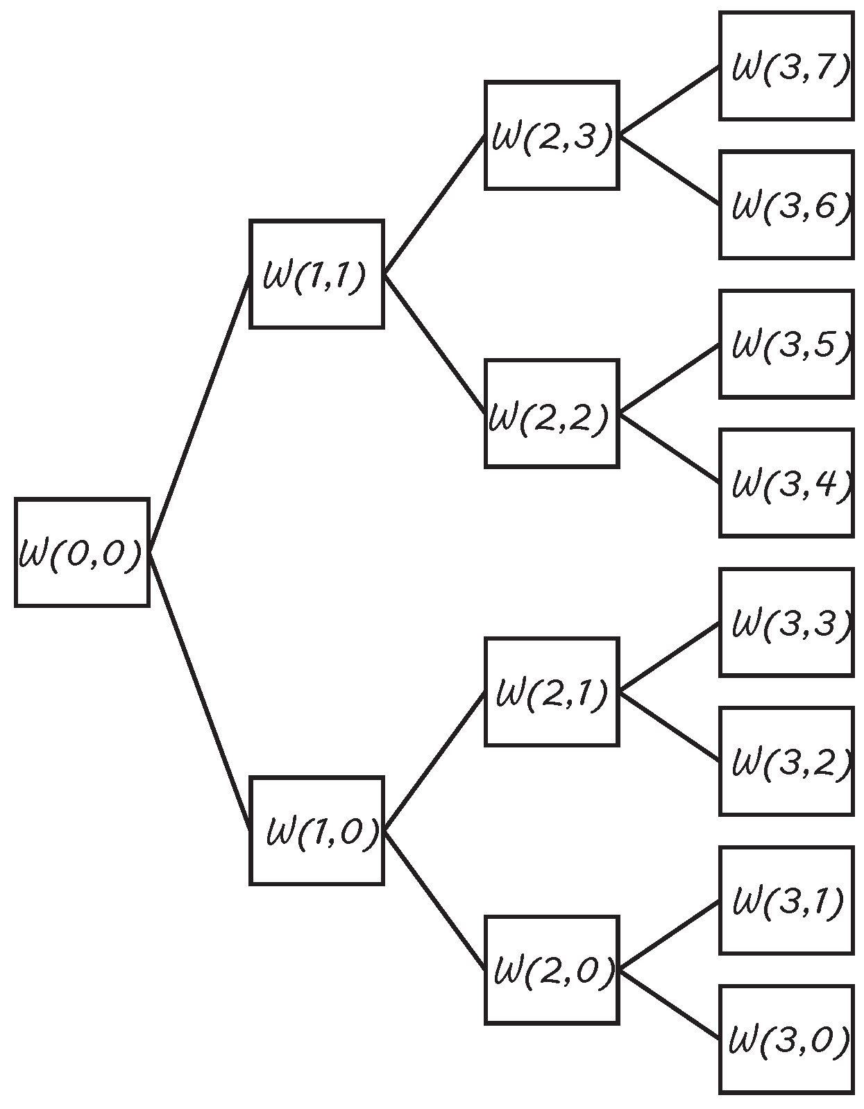
2.2.2. Wavelet Packets Transform

Due to the incapability of MRA to decompose high frequency bands, in 1992, Coifman, Meyer and Wickerhauser developed the Wavelet Packets Transform (WPT). Using WPT, all the approximation and detail information can be decomposed until the desired level. This process can be observed in Figure 4.
The term W ( k , j ) represents the coefficients obtained for a packet, where k is the decomposition level (here, the number of packets obtained is 2 k ) and j is the position of the packet within the decomposition level. Then, each correlation vector W ( k , j ) has the structure of Equation (2):
W ( k , j ) = { w 1 ( k , j ) , . . . , w N ( k , j ) } = { w i ( k , j ) }
WPT has been used in the last years for fault detection in rotating machinery and condition monitoring [52,53]. WPT coefficients can be directly applied for fault detection as they content valuable information about them, according to [54]. Features related to the statistical parameters of WPT coefficients have been used combined with SVM in [55]. It was highlighted in [25] that wavelet energy-based features are often not suitable to detect incipient defects, since slight changes in a signal will be masked. Later, normalized wavelet packet quantifiers were proposed for condition monitoring, such as relative energy [56]. WPT energy has been successfully used to detect incipient induced cracks in shafts at steady state, using vibration signals coming from a rig [33], solving the problem of how to select the best feature. WPT has also been used to detect the appearance of cracks in railway axles during fatigue testing at steady state, using thresholding methods [57]. Signals coming from Jeffcott rotor models during start-up, under different crack conditions simulated using crack breathing functions, have also been successfully analyzed via WPT energy [58].
Studies have also been carried out to examine the application of WPT to detect faults in rotating machinery using signals obtained experimentally from a custom-built rotor kit [59]. The experimental set-up simulated the main operating conditions of rotating machinery, at laboratory scale, which are used in a wide range of industrial applications involving several different pieces of equipment. It has been affirmed that the WPT is a powerful tool for detailed feature extraction. For impulsive faults like rubbing, it is proposed a combined method of WPT and CWT for fault detection.
WPT has also been applied to AE signals [60], showing advantages in the diagnosis at early period crack faults. The diagnosis results obtained were clear, reliable and accurate.

3. Wavelet Transform Parameters Selection

One of the main parameters to take into consideration when using wavelet theory is the selection of the frequency resolution in each zone of the signal. This is determined by the scale range in CWT, and by the decomposition level in DWT.
When using CWT, there are different resolution in frequency and in time at the different zones of the signal, therefore the scale range must be adjusted to get the desired frequency range at a local zone of the signal. The scale range determines the frequency range. The relationship between the scale, s, and the frequency, f, when applying CWT is shown in Equation (3).
f = f ψ · f s s
where f ψ is the central frequency of the wavelet function in Hz, and f s the sampling frequency.
The analysis of the standard deviation of the wavelet scales energy is one of the most important features in distinguishing impulsive and oscillatory transient disturbance, as performed in [61] were a power system transient analysis was performed.
On the other hand, when using DWT, every time the signal is decomposed, the frequency range is divided by two, as demonstrated in Figure 2. When the MRA is applied, not all of the packets are decomposed, due to this the frequency ranges of the different areas of the signal are different. As opposed to MRA, when using WPT, all the packets obtained at each level have the same frequency resolution, until the desired one is reached. Considering the application of WPT using a decomposition level, k, and the global frequency resolution, f s / 2 , (half of the sampling frequency f s in accordance with the Nyquist rule), the frequency resolution of the whole signal is divided into equal parts between the number of packets obtained 2 k . Thus, the frequency resolution, f r , of each packet is given by Equation (4) [36]:
f r = f s / 2 2 k
The value of f r must achieve a compromise between covering the desired range whilst also being small enough to avoid being influenced by other frequencies that may adulterate the results.
In most cases, the decomposition level selected is optimal for one purpose and has been reached after trying several other options [62]. Since all WPT packets have the same frequency resolution, the automatic selection of the optimal scale range or decomposition level becomes easier. An automatic method has been detailed [63] for the selection of features involving sets that produce accurate results in classification for systems. The method utilizes wavelet decomposition and texture statistics. The use of intelligent classification systems has also been used for feature selection (either single-level basis selection, or multiple-level basis selection). Classification results of SVM have also been used at different Signal to Noise Ratios for feature selection [64]. Based on this work, a method to automatically select the optimal decomposition level was proposed in [58]. The method is based on the diagnosis results provided by an ANN. The method proposes an automatic evaluation to diagnose cracks in shafts, trying decomposition levels from two to nine.
Another critical parameter to be selected when applying wavelets is the wavelet function. In the same way it was common to determine the decomposition level of the range scale selection, it is also common to experiment with several possibilities to try to get the optimum wavelet function for the desired purpose. In terms of data compression, several methods are used, as Compression Ratio and Peak Signal to Noise Ratio, this is demonstrated in [65].
In most cases, the selection of the decomposition level and the wavelet function are closely related. For example, when the DWT is applied to remove noise, there are several methods proposed, such as the Signal to Noise Ratio, MAX, and EXP methods [66]. In [67], the decomposition level and the wavelet function are selected in order to minimize the percentage root mean square difference criterion.
For fault detection, there is no optimal way to select the best wavelet function for a specific application. In practice, this can be carried out by comparing the shape of the fault to be detected with the wavelet function to be used. Symmetric wavelets were found to be more effective in singularity analysis, for example, a very narrow pulse-like anti-symmetric wavelet, such as db10 or any higher-order of Daubechies family where it was also found to perform well [59]. Specifically, in crack detection, the maximum cross-correlation coefficients computed between the fault signal and the different wavelet functions from the library will give the optimal wavelet function, as shown in [68]. The Daubechies family, and more specifically the Daubechies order six has been widely used for crack detection due to its proven effectiveness in this field [33,57,69].

4. Results Presentation

Studies about the dynamics of cracked rotors usually do not involve the inverse process of crack detection. Therefore they do not include quantitative results of detection methods. On the other hand, when using intelligent classification systems, it is common to present the results in the form of a success rate percentage.
Recently, the Probability of Detection (POD) curves have been imported from Non Destructive Evaluation (NDE) methods for presenting the results of crack detection in rotors. In NDE methods, POD curves are a normalized parameter used to evaluate the capability of a specified inspection method under specified conditions [70]. Usually, POD is represented versus crack size “a” (length, depth, or, more recently the reflecting area [71]).
The confidence level of these POD curves is a matter of great importance. Usually, the lower 95% confidence bound is shown, which means that 95% of the POD curves constructed would be better than that represented. An NDE crack size, a N D E , may be defined as the crack size that reaches a certain probability of detection with a given confidence level. Figure 5 shows the mean POD(a) curve together with the 95% confidence bound, and the 90/95 crack size (the probability of detection is 90% and the confidence bound is 95%) [72].
Recently, several works regarding crack detection in rotors have used POD curves to present diagnosis results, examples of these can be found in [33,73,74,75].

5. Prospects

In recent years, an extensive volume of research related to cracked rotors diagnosis has been generated. Multiple works applying very different methods have been carried out that have obtained promising results; some of which have been mentioned in the present work. A high number of studies applied novel methods to experimental signals, these also provided quantitative information of the inverse process of crack detection, as a response of the highlights in [1]. Currently, despite the high number of methods applied and the different features used, none of them stands out above the rest. New methodologies appeared to solve the problem of the non-existing standard methodology to select the best wavelet function, the decomposition level, and the features. One of these methods proposed was based on the use of intelligent classification systems. However, this remedy can be worst than the disease since there are again a lot of parameters that must be selected when applying intelligent classification systems. There is no agreement when deciding which intelligent classification system is best, nor a methodology to select optimal functions or values for its parameters. The most common extended methodology is to optimize the success rate percentage.
Several works have published quantitative data about success in results when experimentally diagnosing a specific fault, in a specific element, belonging to a specific machine, and working under specific conditions. It would be appropriate to study how many of the techniques applied are robust and still work when these very specific conditions are altered, or under what range of conditions these techniques still work; for example, what mounting; what speed; what load; whether they work when multiple faults are present; or when faults are in a different location. Another critical issue is the decision over what criteria should be used in the verification of whether a technique works or not. There is a need to benchmark the different techniques that have proven effectiveness in this area. So, it would be very useful to establish standard comparison parameters, statistically representative, such as POD curves and the computational cost. Benchmarking of the different methods under many different conditions would make it possible to check if one of them stands out. These kinds of studies are required in order to achieve the aim of a method of condition monitoring that is general while also being robust and reliable.

6. Conclusions

Here, the literature relating to the application of the Wavelet theory to cracked rotor diagnosis has been briefly reviewed. This revision of the literature has covered the different ways in which Wavelet Transform has been applied, its combination with intelligent classification systems, wavelet parameters selection, and the presentation of results. The future prospects for the techniques currently used have been discussed. It is concluded that there are a lot of different techniques that have worked properly for crack diagnosis, but only under certain conditions. Extrapolation of these methods to other conditions, and benchmarking between the different proposed techniques for crack detection are needed.

Acknowledgments

The authors would like to thank the Spanish government for financing through the CDTI project RANKINE21 IDI-20101560.

Author Contributions

The three authors have been working in this field for several years. Juan C. García-Prada has wide experience in this area, and has looked a lot of bibliography and was in charge of the introduction section. Cristina Castejón has wide experience in working with wavelets and was in charge of the wavelets section and its bibliography. María J. Gómez wrote the paper and was in charge of the section of results presentation and prospects.

Conflicts of Interest

The authors declare no conflict of interest.

Abbreviations/Nomenclature

The following abbreviations are used in this manuscript:
CWT: Continuous Wavelet transform
FEA: Finite Elements Approach
WFEM: Wavelet Finite Element Methods
GA: Genetic algorithms
FT: Fourier transform
HT: Hilbert transform
WT: Wavelet transform
AE: Acoustic Emission
STFT: Short Time Fourier transform
CWT: Continuous Wavelet transform
XWT: Cross Wavelet Transform
ANN: Artificial Neural Network
DWT: Discrete Wavelet Transform
MRA: Multiresolution analysis
WPT: Wavelet Packets transform
SVM: Support Vector Machines
NDE: Non Destructive Evaluation
POD: Probability of detection
t: Time
N: Number of samples for a time domain signal
c: Scale parameter in CWT
b: Shift parameter in CWT
s: Scale range evaluated in CWT
ψ: Wavelet function
w: Weighting function
x: Time domain signal
A: Approximation information
D: Detail information
k: Decomposition level
j: Position of a packet within decomposition level
W ( k , j ) : WPT coefficients
f: Frequency
f ψ : Central frequency of the wavelet function
f s : Sampling frequency
f r : Frequency resolution of a packet in WPT
a: Crack size
a N D E : Crack size that reaches certain POD at a given confidence level

References

  1. Bachschmid, N.; Penacci, P. Crack effects in rotordynamics. Mech. Syst. Signal Process. 2008, 22, 761–762. [Google Scholar] [CrossRef] [Green Version]
  2. Sekhar, A.S. Multiple cracks effects and identification. Mech. Syst. Signal Process. 2008, 22, 845–878. [Google Scholar] [CrossRef]
  3. Papadopoulos, C.A. The strain energy release approach for modeling cracks in rotors: A state of the art review. Mech. Syst. Signal Process. 2008, 22, 763–789. [Google Scholar] [CrossRef]
  4. Sekhar, A.S. Identification of unbalance and crack acting simultaneously in a rotor system: Modal expansion versus reduced basis dynamic expansion. J. Vib. Control 2005, 11, 1125–1145. [Google Scholar] [CrossRef]
  5. Pennacchi, P.; Bachschmid, N.; Vania, A. A model-based identification method of transverse cracks in rotating shafts suitable for industrial machines. Mech. Syst. Signal Process. 2006, 20, 2112–2147. [Google Scholar] [CrossRef] [Green Version]
  6. Kulesza, Z.; Sawicki, J.T. Rigid finite element model of a cracked rotor. J. Sound Vib. 2012, 331, 4145–4169. [Google Scholar] [CrossRef]
  7. Sekhar, A.S.; Prabhu, B.S. Crack detection and vibration characteristics of cracked shafts. J. Sound Vib. 1992, 157, 375–381. [Google Scholar] [CrossRef]
  8. Gomez-Mancilla, J.; Sinou, J.; Nosov, V.R. The influence of crack-imbalance orientation and orbital evolution for an extended cracked Jeffcott rotor. C. R. Mecanique 2004, 332, 995–962. [Google Scholar] [CrossRef]
  9. Bachschmid, N.; Penacci, P.; Tanzi, E. Some remarks on breathing mechanism, on non-linear effects and on slant and helicoidal cracks. Mech. Syst. Signal Process. 2008, 22, 879–904. [Google Scholar] [CrossRef] [Green Version]
  10. Al-Shudeifat, A.; Butcher, E.A. New breathing functions for the transverse breathing crack of the cracked rotor system: Approach for critical and subcritical hermonic analysis. J. Sound Vib. 2011, 330, 526–544. [Google Scholar] [CrossRef]
  11. Gasch, R. Dynamic behaviour of the Laval rotor with a transverse crack. Mech. Syst.Signal Process. 2008, 22, 790–804. [Google Scholar] [CrossRef]
  12. Ishida, Y. Cracked rotors: Industrial machine case histories and nonlinear effects shown by simple Jeffcott rotor. Mech. Syst. Signal Process. 2008, 22, 805–817. [Google Scholar] [CrossRef]
  13. Kumar, C.; Rastogi, V. A Brief Review on Dynamics of a Cracked Rotor. Int. J. Rotat. Mach. 2009, 2009, 1–6. [Google Scholar] [CrossRef]
  14. Xiang, J.; Zhong, Y.; Chen, X.; He, Z. Crack detection in a shaft by combination of wavelet-based elements and genetic algorithm. Int. J. Solids Struct. 2008, 45, 4782–4795. [Google Scholar] [CrossRef]
  15. Zhao, B. The Application of Wavelet Finite Element Method on the Crack Recognition of the Gate Rotor Shaft of the Single Screw Compressor. Adv. Sci. Lett. 2011, 4, 3721–3726. [Google Scholar] [CrossRef]
  16. Li, B.; Dong, H. Quantitative Identification of Multiple Cracks in a Rotor Utilizing Wavelet Finite Element Method. CMES-Comput. Model. Eng. Sci. 2012, 84, 205–228. [Google Scholar]
  17. Sekhar, A.S. On-line rotor fault identification by combined model and signal based approach. Noise Vib. Worldw. 2004, 35, 16–30. [Google Scholar] [CrossRef]
  18. Feldman, M.; Seibold, S. Damage diagnosis of rotors: Application of Hubert transform and multihypothesis testing. J. Vib. Control 1999, 5, 421–442. [Google Scholar] [CrossRef]
  19. Sabnavis, G.; Kirk, R.G.; Kasarda, M.; Quinn, D. Cracked shaft detection and diagnostics: A literature review. Shock Vib. Dig. 2004, 36, 287–296. [Google Scholar] [CrossRef]
  20. Babu, T.R.; Srikanth, S.; Sekhar, A.S. Hilbert-Huang transform for detection and monitoring of crack in a transient rotor. Mech. Syst. Signal Process. 2008, 22, 905–914. [Google Scholar] [CrossRef]
  21. Jiao, W.; Yang, S.; Chang, Y.; Yan, G.; Hu, J. Detecting a Cracked Rotor with HHT-based Time-Frequency Representation. In Proceedings of the IEEE International Conference on Automation and Logistics, Qingdao, China, 1–3 September 2008; pp. 790–793.
  22. Mallat, S. A Wavelet Tour of Signal Processing; Academic Press: Burlington, VT, USA, 2009. [Google Scholar]
  23. Gu, D.; Kim, J.; Kelimu, T.; Huh, S.; Choi, B. Evaluation of the use of envelope analysis and DWT on AE signals generated from degrading shafts. Mater. Sci. Eng. 2012, 177, 1683–1690. [Google Scholar] [CrossRef]
  24. Elforjani, M.; Mba, D. Detecting Natural Crack Initiation and Growth in Slow Speed Shafts with the Acoustic Emission Technology. Eng. Fail. Anal. 2009, 16, 2121–2129. [Google Scholar] [CrossRef] [Green Version]
  25. Peng, Z.K.; Chu, F.L. Application of the wavelet Transform in machine condition monitoring and fault diagnostics: A review with bibliography. Mech. Syst. Signal Process. 2004, 18, 199–221. [Google Scholar] [CrossRef]
  26. Mallat, S. A Theory for Multiresolution Signal Decomposition: The Wavelet Representation. IEEE Trans. Pattern Anal. Mach. Intell. 1989, 11, 674–693. [Google Scholar] [CrossRef]
  27. Vignolo, L.; Milone, D.H.; Rufiner, H.L. Genetic wavelet packets for speech recognition. Expert Syst. Appl. 2011, 40, 2350–2359. [Google Scholar] [CrossRef]
  28. Avci, E.; Akpolat, Z.H. Speech recognition using a wavelet packet adaptive network based fuzzy inference system. Expert Syst. Appl. 2006, 31, 495–503. [Google Scholar] [CrossRef]
  29. Mercorelli, P. A denoising procedure using wavelet packets for instantaneous detection of pantograph oscillations. Mech. Syst. Signal Process. 2013, 35, 137–149. [Google Scholar] [CrossRef]
  30. Premanode, B.; Vongprasert, J.; Toumazou, C. Noise Reduction for Nonlinear Nonstationary Time Series Data using Averaging Intrinsic Mode Function. Algorithms 2013, 6, 407–429. [Google Scholar] [CrossRef]
  31. Tinati, M.A.; Mozaffary, B. A Wavelet Packets Approach to Elecrocardiograph Baseline Drift Cancellation. Int. J. Biomed. Imaging 2006, 2006, 1–9. [Google Scholar] [CrossRef] [PubMed]
  32. Camps, A.; Tarongí, J.M. RFI Mitigation in Microwave Radiometry Using Wavelets. Algorithms 2009, 2, 1248–1262. [Google Scholar] [CrossRef] [Green Version]
  33. Gómez, M.J.; Castejón, C.; García-Prada, J.C. Crack detection in rotating shafts based on the 3x energy. Analytical and experimental analysis. Mech. Mach. Theory 2016, 96, 94–106. [Google Scholar] [CrossRef]
  34. Lou, X.; Loparo, K.A. Bearing fault diagnosis based on wavelet transform and fuzzy inference. Mech. Syst. Signal Process. 2004, 18, 1077–1095. [Google Scholar] [CrossRef]
  35. Castejón, C.; Lara, O.; García-Prada, J.C. Automated diagnosis of rolling bearings using MRA and neural networks. Mech. Syst. Signal Process. 2010, 24, 289–299. [Google Scholar] [CrossRef]
  36. Gómez, M.J.; Castejón, C.; García-Prada, J.C. Incipient Fault Detection in Bearings Through the use of WPT Energy and Neural Networks. In Advances in Condition Monitoring of Machinery in Non-Stationary Operations; Springer: Berlin, Germany, 2014; pp. 63–72. [Google Scholar]
  37. Wang, W.J.; McFaden, P.D. Application of wavelets to gearbox vibration signals for fault detection. J. Sound Vib. 1996, 192, 927–939. [Google Scholar] [CrossRef]
  38. Rafiee, J.; Rafiee, M.A.; Tse, P.W. Application of mother wavelet functions for automatic gear and bearing fault diagnosis. Expert Syst. Appl. 2010, 37, 4568–4579. [Google Scholar] [CrossRef]
  39. Vernekar, K.; Kumar, H.; Gandharan, K.V. Gear Fault Detection Using Vibration Analysis and Continuous Wavelet Transform. Proced. Mater. Sci. 2014, 5, 1846–1852. [Google Scholar] [CrossRef]
  40. Douka, E.; Loutridis, S.; Trochidis, A. Crack Identification in Beams Using Wavelet Analysis. Int. J. Solids Struct. 2003, 40, 3557–3569. [Google Scholar] [CrossRef]
  41. Nagaraju, C.; Narayana Rao, K.; Mallikarjuna Rao, K. Application of 3D wavelet transforms for crack detection in rotor systems. Sadhana 2009, 34, 407–419. [Google Scholar] [CrossRef]
  42. Babu, T.R.; Sekhar, A.S. Shaft Crack Identification Using Artificial Neural Networks and Wavelet Transform Data of a Transient Rotor. Adv. Vib. Eng. 2010, 9, 207–214. [Google Scholar]
  43. Huang, Y. Advances in Artificial Neural Networks—Methodological Development and Application. Algorithms 2009, 2, 979–1007. [Google Scholar] [CrossRef]
  44. Sinou, J.J. An Experimental Investigation of Condition Monitoring for Notched Rotors Through Transient Signals and Wavelet Transform. Exp. Mech. 2009, 5, 683–695. [Google Scholar] [CrossRef]
  45. Srinivas, H.K.; Srinivasan, K.S.; Umesh, K.N. Role of an Artificial Neural Network and a Wavelet Transform for Condition Monitoring of the Combined Faults of Unbalance and Cracked Rotors. Int. J. Acoust. Vib. 2010, 15, 121–127. [Google Scholar]
  46. Hee, L.M.; Leong, M.S.; Hui, K.H. Analysis of Residual Wavelet Scalogram for Machinery Fault Diagnosis. Mater. Ind. Manuf. Eng. Res. Adv. 2014, 845, 113–117. [Google Scholar] [CrossRef]
  47. Smith, J. Mathematics of the Discrete Fourier Transform (DFT); W3K: Charleston, SC, USA, 2007. [Google Scholar]
  48. Jensen, A.; la Cour-Harbo, A. Ripples in Mathematics; Springer: Berlin, Germany, 2000. [Google Scholar]
  49. Sawicki, J.T.; Sen, A.K.; Litak, G. Multiresolution Wavelet Analysis of the Dynamics of a Cracked Rotor. Int. J. Rotat. Mach. 2009, 2009, 1–8. [Google Scholar] [CrossRef]
  50. Castejón, C.; García-Prada, J.C.; Gómez, M.J.; Meneses, J.T. Automatic Detection of Cracked Rotors combining Multiresolution Analysis and Artificial Neural Networks. J. Vib. Control 2014. [Google Scholar] [CrossRef]
  51. Eftekharnejad, B.K.; Addali, A.; Mba, D. Shaft crack diagnostics in a gearbox. Appl. Acoust. 2012, 73, 723–733. [Google Scholar] [CrossRef]
  52. Liu, B.; Ling, S.F. Machinery diagnostic based on wavelet packets. J. Sound Vib. 1997, 3, 5–17. [Google Scholar]
  53. Bin, G.F.; Gao, J.J.; Li, X.J.; Dhillon, B.S. Early fault diagnosis of rotating machinery based on wavelet packets-Empirical Mode decomposition feature extraction and neural network. Mech. Syst. Signal Process. 2012, 27, 696–711. [Google Scholar] [CrossRef]
  54. Hu, Q.; He, Z.; Zhang, Z. Fault diagnosis of rotating machinery based on improved wavelet package transform and SVMs ensemble. Mech. Syst. Signal Process. 2007, 21, 688–705. [Google Scholar] [CrossRef]
  55. Shen, C.; Wang, D.; Kong, F.; Tse, P.W. Fault diagnosis of rotating machinery based on the statistical parameters of wavelet packet paving and a generic support vector regressive classifier. Meas. J. Int. Meas. Confed. 2013, 46, 1551–1564. [Google Scholar] [CrossRef]
  56. Feng, Y.; Schlindwein, F.S.; Li, X.J. Normalized wavelet packets quantifiers for condition monitoring. Mech. Syst. Signal Process. 2009, 23, 712–723. [Google Scholar] [CrossRef]
  57. Gómez, M.J.; Castejón, C.; García-Prada, J.C. New stopping criteria for crack detection during fatigue tests of failway axles. Eng. Fail. Anal. 2015, 56, 530–537. [Google Scholar] [CrossRef]
  58. Castejón, C.; Gómez, M.J.; García-Prada, J.C.; Ordoñez, A.; Rubio, H. Automatic Detection of Cracked Rotors Combining Multiresolution Analysis and Artificial Neural Networks. Int. J. Acoust. Vib. 2015, 20, 95–100. [Google Scholar] [CrossRef]
  59. Al-Badour, F.; Sunar, M.; Cheded, L. Vibration analysis of rotating machinery using time-frequency analysis and wavelet techniques. Mech. Syst. Signal Process. 2011, 25, 2083–2101. [Google Scholar] [CrossRef]
  60. He, K.F.; Li, X.J.; Li, X.C. Research on Feature Extraction Experiment for Acoustic Emission Signal of Rotor Crack Fault. Mech. Eng. Green Manuf. 2010, 34–35, 1005–1009. [Google Scholar] [CrossRef]
  61. Tan, R.H.G.; Ramachandaramurthy, V.K. Power System Transient Analysis using Scale Selection Wavelet Transform. In Proceedings of the Tencon IEEE Region 10 Conference Proceedings, Singapore, 23–26 January 2009; Volume 1–4, pp. 2171–2176.
  62. Kim, J.; Cho, B.H. An innovative approach for characteristic analysis and state-of-health diagnosis for a Li-ion cell based on the discrete wavelet transform. J. Power Sour. 2014, 260, 115–130. [Google Scholar] [CrossRef]
  63. Dessauer, M.P.; Dua, S. Discriminative Features and Classification Methods for Accurate Classification. Evolut. Bio-inspir. Comput. Theory Appl. 2010. [Google Scholar] [CrossRef]
  64. Safara, F.; Doraisamy, S.; Azman, A. Multi-level basis selection of wavelet packet decomposition tree for heart sound classification. Comput. Biol. Med. 2013, 43, 1407–1414. [Google Scholar] [CrossRef] [PubMed] [Green Version]
  65. Rehman, M.; Touqir, I.; Batool, W. Selection of Optimal Wavelet Bases for Image Compression using SPIHT Algorithm. In Proceedings of the Seven International Conferente on Mahcine Vision, Milan, Italy, 19 November 2014; Volume 9445.
  66. Omari, T.; Bereksi-Reguig, F. An Automatic Wavelet Selection Scheme for Heart Sounds Denoising. Proc. IWBBIO Int. Work-Conf. Bioinform. Biomed. Eng. 2015, 13. [Google Scholar] [CrossRef]
  67. Kumar, A.; Sing, M. Optimal Selection of Wavelet Function and Decomposition Level for Removal ECG Signal Artifacts. J. Med. Imaging Health Inform. 2015, 5, 138–146. [Google Scholar] [CrossRef]
  68. Li, B.; Xia, H. Research on Feature Recognition of Nuclear Power Equipment Based on the Optimal Wavelet Basis. In Proceedings of the 21st International Conference on Nuclear Engineering, Chengdu, China, 29 July–2 August 2013; Volume 5.
  69. Gómez, M.J.; Castejón, C.; García-Prada, J.C. Experimental development and validation of a vibration-based technique for crack detection in a shaft. Proc. 9th IFTOMM Int. Conf. Rotor Dyn. 2015, 21, 373–383. [Google Scholar]
  70. Rummel, W.D. Nondestructive inspection reliability history, status and future path. In Proceedings of the 18th World Conference on Nondestructive, Durban, South Africa, 16–20 April 2010.
  71. Cantini, S.; Beretta, S. Structural Reliability Assessment of Railway Axles; Lucchini RS: Lovere, Italy, 2011. [Google Scholar]
  72. Bachschmid, N.; Pennacchi, P.; Tanzi, E. Cracked Rotors: A Survey on Static and Dynamic Behaviour Including Modelling and Diagnosis; Springer: Berlin, Germany, 2010. [Google Scholar]
  73. Gao, C.W.; Meeker, W.Q. A Statistical Method for Crack Detection from Vibrothermography Inspection Data. Qual. Technol. Quant. Manag. 2012, 9, 59–77. [Google Scholar]
  74. Gao, C.W.; Meeker, W.Q.; Mayton, D. Detecting cracks in aircracft engine fan blades using vibrothermography nondestructive evaluation. Reliab. Eng. Syst. Saf. 2014, 131, 229–235. [Google Scholar] [CrossRef]
  75. Gagar, D.; Foote, P.; Irving, P.E. Detecting and Monitoring of Fatigue Cracks in Metallic Structures Using Acoustic Emission: Routes to Quantification of Probability of Detection. Advanced Materials Research 2014, 891–892, 1268–1274. [Google Scholar] [CrossRef]
Figure 1. Signal in the time domain and its CWT.
Algorithms 09 00019 g001
Figure 2. DWT decomposition of a signal (S) in approximation information (A) and detail information (D) using filters.
Algorithms 09 00019 g002
Figure 3. MRA decomposition procedure until decomposition level 3 of decomposition. Each decomposition is based on DWT (see Figure 2).
Algorithms 09 00019 g003
Figure 4. WPT decomposition process until level 3 of decomposition, where each decomposition is performed based on DWT (see Figure 2).
Algorithms 09 00019 g004
Figure 5. POD curve, showing mean value, 95% confidence bound, and 90/95 crack size a N D E .
Algorithms 09 00019 g005

