1. Introduction
Airport operations are widely recognized to be one of the main bottlenecks of the current Air Traffic Management (ATM) system. The Single European Sky ATM Research (SESAR) program, which is aimed at renovating the European ATM system, is, indeed, also focused on modifying the future airport operations concept, dealt with in the Airport Operations Work Package (WP 6).
One of the basic principles driving this transformation is the proactive management of airport performance [
1], e.g., in terms of capacity. This is done by integration of the local Airport Operations Plan (AOP) in the global Network Operations Plan (NOP) and sharing data across all airport stakeholders, which shall perform timely updates to the AOP under agreed rules and procedures. The reference concept upon which this novel airport operations view is built is Airport-Collaborative Decision-Making (A-CDM), for which a standard term of reference has been recently updated in [
2].
The present paper deals with the problem of managing aircraft movement on an airport surface, taking into account planning and routing functions for aircraft, while being consistent with the airport operations concept envisioned by SESAR [
3]. As airport dimensions, complexity and surface traffic steadily increase, the current first-come first-served approach with conflict detection and resolution performed by Air Traffic Controllers (ATCo) is not capable of dealing efficiently with the problem of interest. Automated decision support systems are under study and/or development for supporting ATCos decision-making in selecting the paths of all aircraft and the time to command the off block procedure start for departing ones. The problem is usually tackled describing the airport surface system by network and graph theory. In this way, the ground-movement process is abstracted into a mixed-integer-continuous-program [
4,
5,
6,
7,
8,
9], which is either linearized, yielding a Mixed-Integer-Linear-Problem (MILP) [
4,
5,
6,
7], or approached by stochastic optimization algorithms [
8]. A thorough overview of possible problem settings and popular approaches can be found in [
9], to which the interested reader can refer. The common trait of the usual ground movement problem’s formulations is that they easily result in a computationally intractable problem, and some simplifying assumptions must be introduced, such as bounding aircraft taxi speeds [
6], applying a receding horizon approximation [
4,
7] and linearizing the continuous problem part [
4,
6,
7,
9].
This paper proposes an algorithm suitable for tackling the ground movement problem. This Taxi Route Planner (XRP) tool aims at minimizing the holding time of aircraft that are maneuvering on airport taxiways, for both arriving and departing aircraft. This is done in two consecutive steps, that is, a standalone, shortest path solution from runway to apron (or vice versa), neglecting the presence of other aircraft on the airport surface, followed by a conflict detection and resolution task that attempts to reduce and possibly nullify the number of conflicts generated in the first phase. In this way, the computationally intractable problem is simplified by decomposition, and a suboptimal solution can always be found within a pre-specified time interval, which makes the algorithm suitable for practical use in true-world airport operations.
The paper is organized as follows. First, a possible scenario for future airport operations, which is taken as a reference in developing the algorithm, is outlined following the latest SESAR’s concept of operations. Subsequently, target requirements for the system are derived. Then, the algorithmic structure of the tool is laid out, and its contents discussed in detail. An example application on an Italian airport exemplifies how true-world applications can be modeled to suit the algorithm’s needs. Last, a preliminary assessment of the algorithm’s performance is presented.
2. Airport Operations Reference Scenario
In order to define the functionalities of the XRP decision support tool, we introduce in this section a series of general assumptions that contribute in defining a reference scenario for the airport environment in which the XRP is intended to operate. As stated in the introduction, Airport-Collaborative Decision-Making (A-CDM) is the key element of the reference scenario. A-CDM is a concept that aims at improving air traffic flow and capacity management at airports by reducing delays, improving the predictability of events and optimizing the utilization of resources. The decision making by the Airport CDM partners is facilitated by sharing accurate and timely information and by adapted procedures, mechanisms and tools [
2]. We will assume that the arrival and departure flows are managed by two of such advanced ATCo tools, which cooperate with the Airport-CDM concept by sharing information and optimizing arrivals and departures, as follows [
2]:
Arrival Manager (AMAN), which is an arrival flow management tool, optimizes the traffic flow into a Terminal Management Area (TMA) and/or runway(s) by calculating Target Landing Time (TLDT), taking various constraints and preferences into account.
Departure Manager (DMAN), which is a planning system to improve the departure flows at an airport by calculating Target Take-Off Time (TTOT) and Target Start-up Approval Time (TSAT) for each flight, taking multiple constraints and preferences into account.
The arrival and departure processes we will use as a reference for deriving the XRP functionalities are developed according to EUROCONTROL’s Milestones Approach, part of the Airport-CDM concept. In practice, the milestones approach standardizes, as possible, the sequence of events, denoted as “milestones”, that shall occur to the typical profile of a flight transiting at an airport. We focus only on the reference arrival and departure processes, enhancing the elements relevant to the taxi route assignment, referring the interested reader to [
2].
A major milestone for inbound flights, at least from the routing standpoint, is the Estimated Landing Time (ELDT). Given the guidelines for information sharing in the reference A-CDM concept, relevant information of an inbound flight is available with reasonable accuracy to the routing planning process at ELDT—20 min. The AMAN tool is in charge of determining the optimal sequence of ELDTs for all inbound flights, improving the exploitation of runways’ capacity and increasing punctuality. For doing so, an estimate of the time at which the aircraft will arrive at its assigned gate, the Estimated In-Block Time (EIBT), shall be computed by means of the Estimated Taxi in Time (EXIT), which is the estimated taxi time between landing and in-block. The reference inter-operational concept assumed in this paper is that AMAN computes the optimal ELDT sequence. The ELDT sequence is then delivered to XRP, which determines the EIBT for each inbound aircraft, by means of an accurate computation of the EXIT.
For an outbound flight, the milestone sequence is more involved, also when focusing only on the aspects relevant to the route assignment problem. A major role is played by the Target Off-Block Time (TOBT), which is the time that the aircraft operator and handling agents estimate that an aircraft will be ready, all doors closed, boarding bridge removed, push back vehicle present, ready to start-up/push back immediately upon reception of clearance from the control tower (TWR). The availability of an accurate TOBT is the pre-requisite for performing a collaborative pre-departure sequence optimization. Given the guidelines for information sharing in the reference A-CDM concept, the relevant information of an inbound flight is available with reasonable accuracy to the routing planning process around 20 min before off-block. After a certain amount of time the TOBT is issued, the ATC issues the TSAT: the time that an aircraft can expect to receive start-up/push back approval. The DMAN tool is in charge of determining the sequence of TSATs for all outbound flights, computing the optimal sequence of TTOT for all runways and all outbound flights, taking into account multiple preferences and constraints, such as the available runways’ capacity, wake vortex separations, slot enforcement, arrivals data from AMAN, etc. For doing so, it also takes into account the earliest time at which each aircraft can be reasonably requested to be at the runway, ready for line-up and take-off. In order to estimate such a time, it uses the TOBT as the earliest time an aircraft can be expected to be off-block and relates this condition to take-off by means of the Estimated Taxi-Out Time (EXOT), which is the estimated taxi time between off-block and take-off. The reference inter-operational concept assumed in this paper is that DMAN computes the optimal TTOT sequence using its own EXOT estimates. The TTOT sequence is then delivered to XRP, which determines the TSAT sequence that allows outbound aircraft to meet the assigned TTOT.
Reference Taxi Timelines for Inbound and Outbound Flights
In order to define more precisely the criteria against which the taxi-route optimality is judged, as well as all the constraints affecting the taxi route assignment problem, we shall break down the timeline of the reference taxi process for both inbound and outbound flights, EXIT and EXOT, respectively.
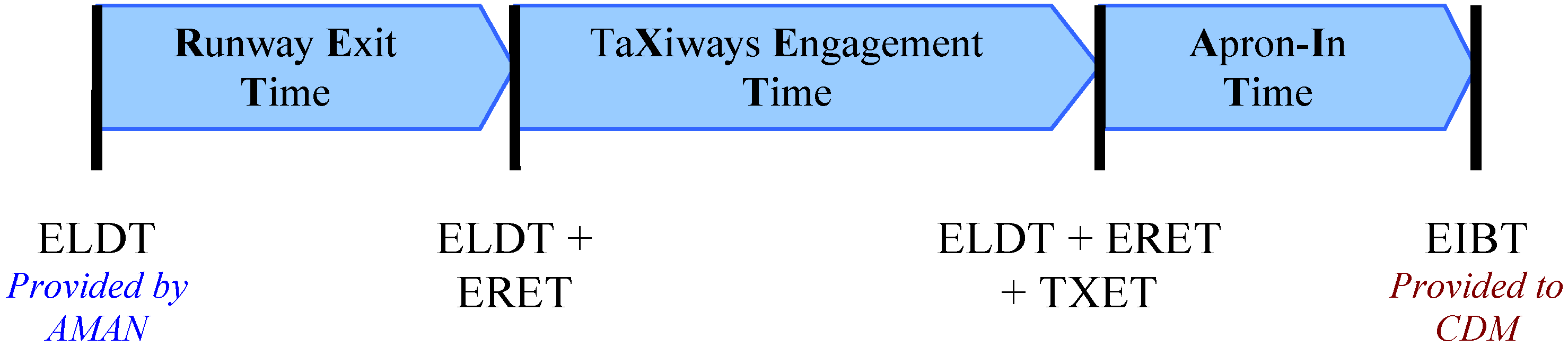
Considering inbound flights, after touchdown, the aircraft has to complete the landing and free the runway. This part of the process is constrained by international regulation to occur as soon as possible and cannot be included in any route planning process. As a consequence, it may be only estimated by the XRP and is denoted as the Estimated Runway Exit Time (ERET). Then, the aircraft enters the airport taxiway system. This phase is obviously subject to route planning and optimization. The time necessary to complete this phase is thus determined by the XRP and shall be a target for the relevant ATCo, denoted as the Target Taxiways Engagement Time (TXET). At last, the aircraft exits the airport’s taxiway system and shall enter the apron. The time necessary to complete this phase is estimated by a purposely developed apron model [
10] and is denoted as Estimated Apron in Time (EAIT). The following relationship is established by the EXIT breakdown (
Figure 1), relating the ELDT provided by AMAN to the EIBT, which is of interest to multiple stakeholders and shall be delivered by the XRP to the CDM.
Figure 1.
Reference Estimated Taxi in Time (EXIT) breakdown. ELDT, Estimated Landing Time; AMAN, Arrival Manager; ERET, Estimated Runway Exit Time; TXET, Target Taxiways Engagement Time; EIBT, Estimated In-Block Time.
Figure 1.
Reference Estimated Taxi in Time (EXIT) breakdown. ELDT, Estimated Landing Time; AMAN, Arrival Manager; ERET, Estimated Runway Exit Time; TXET, Target Taxiways Engagement Time; EIBT, Estimated In-Block Time.
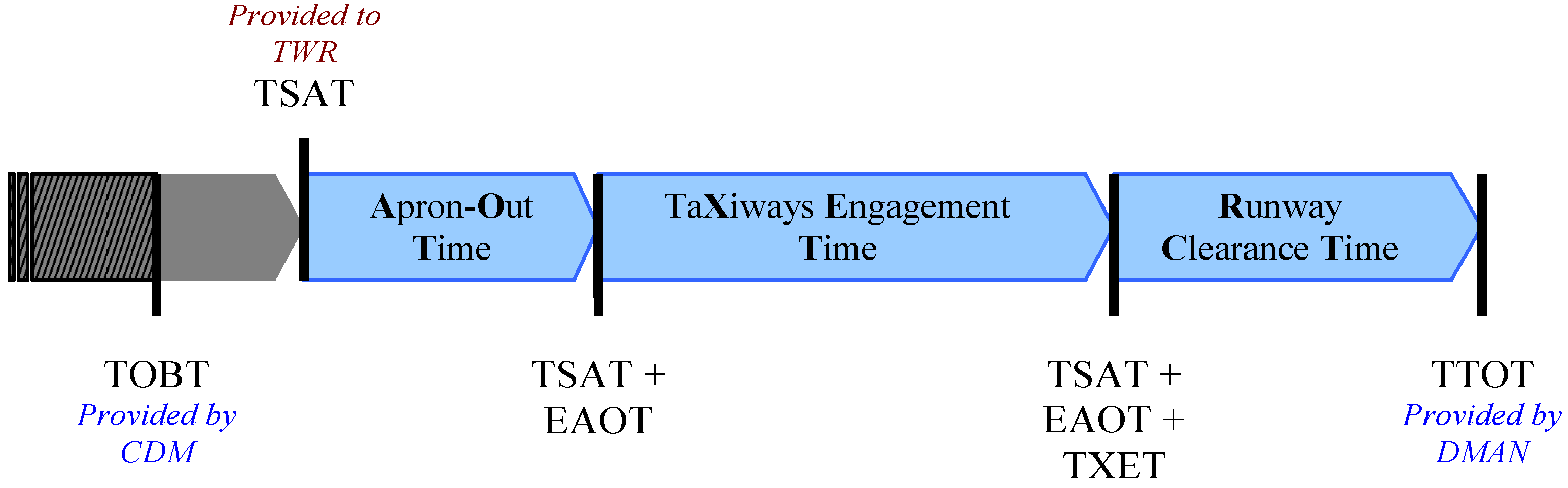
Considering outbound flights, off-block is estimated to not occur prior to TOBT by the aircraft operator and handling agents. The ATCo, upon suggestion by the XRP, has the possibility to delay the off-block, specifying its own target time for starting the off-block process (TSAT). Then, upon completion of the push-back (if applicable) the aircraft shall exit the apron. Again, the time necessary to complete this phase is estimated by a purposely developed apron model [
10] and is denoted as Estimated Apron-Out Time (EAOT). Then, the aircraft enters the airport’s taxiway system. This phase is obviously subject to route planning and optimization. The time necessary to complete this phase is thus determined by the XRP and shall be a target for the ATCo, denoted as TXET, as in the arrival phase. At last, the aircraft arrives at the Runway Holding Position (RHP), where the TWR is in charge of delivering the line-up and take-off clearances to the aircraft. It is clear that the XRP has no control on this phase, as well, whose duration is only estimated and denoted as Estimated Runway Clearance Time (ERCT). The following relationship is established by the EXOT breakdown (
Figure 2). It relates the TSAT, delivered by the XRP to TWR, to the TXET optimized by the XRP in order both to meet the TTOT provided by DMAN and to comply with the TOBT delivered by the CDM.
Figure 2.
Reference Estimated Taxi-Out Time (EXOT) breakdown. TWR; TSAT, Target Start-up Approval Time; TOBT, Target Off-Block Time; CDM, Collaborative Decision-Making; EAOT, Estimated Apron-Out Time; TTOT, Target Take-Off Time.
Figure 2.
Reference Estimated Taxi-Out Time (EXOT) breakdown. TWR; TSAT, Target Start-up Approval Time; TOBT, Target Off-Block Time; CDM, Collaborative Decision-Making; EAOT, Estimated Apron-Out Time; TTOT, Target Take-Off Time.
3. Target Operational Requirements
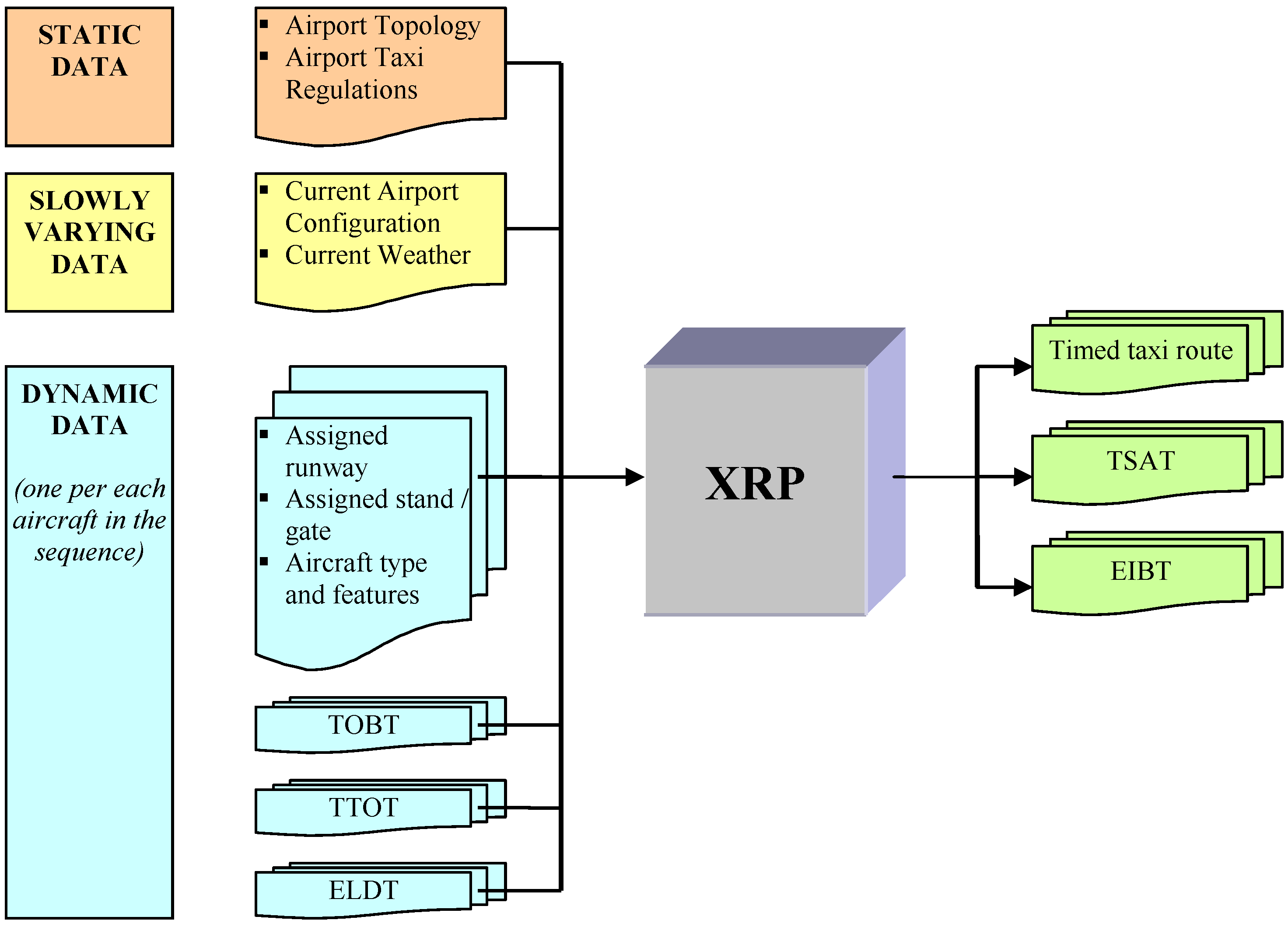
The XRP shall output the TSAT and EIBT, consistently with the previous equations. In order to compute such variables, the XRP is in charge of computing and optimizing the TXET. Moreover, the XRP shall also suggest the taxi route each aircraft shall follow. The XRP thus outputs a timed taxi route, which is a sequence of “vertices”,
i.e., points of the airport’s taxiway system, which the aircraft shall follow in the specified order. Each vertex of the sequence has a time-tag, which specifies at which time epoch the aircraft is expected to reach, leave or cross the point. The TXET is obtained by the difference of the relevant vertices’ time tags. The constraints to which the timed taxi route shall comply are:
The first and last vertices shall be consistent with the apron exit point/runway exit point and holding position/apron entry point for outbound/inbound traffic, respectively.
The route shall be consistent with the airport topology, with the current airport configuration, e.g., in terms of runways used for landings, runways used for departures, taxiways closed or restricted due to weather or maintenance operations, with airport taxi regulations, depending on weather and aircraft parameters, such as wingspan, gross weight, etc.
All routes shall be consistent with the expected airport surface traffic, e.g., no vertices can receive two aircraft concurrently.
Timing shall be consistent with ELDT for arrivals and with TOBT and TTOT for departures, via Equations (1) and (2).
Feasible timed taxi routes shall thus comply with all the previous constraints. Among feasible timed routes, the algorithm shall determine the optimal one. In order for a timed route to be optimal, TXET shall be minimized. This allows gaining benefits in terms of the safety of airport surface operations (less concurrently moving aircraft on the surface implies reduced potentials for conflicts, reduced controller workload,
etc.) and gaining cost/environmental benefits (minimizing taxi times allows for reduced fuel consumption). Furthermore, conflicts of taxi routes shall be avoided if feasible or else minimized to the minimum possible extent. The resulting XRP input-output interface is summarized in
Figure 3.
Figure 3.
Taxi route planner input/output interface. XRP, Taxi Route Planner.
Figure 3.
Taxi route planner input/output interface. XRP, Taxi Route Planner.
4. Route Planning Algorithm
As previously discussed, the XRP algorithm can be thought of as the outcome of two different consecutive steps. First, a standalone, shortest path solution from runway to apron (or vice versa), neglecting the presence of other aircraft on the airport surface, is sought for all aircraft in the planning horizon. This route, which is clearly the one yielding the minimum time the aircraft can potentially spend on the taxiways, does not take into account the constraints due to other traffic on the airport surface. Thus, this solution is amended by a conflict detection and resolution task that attempts to reduce and possibly nullify the number of conflicts generated in the first phase.
4.1. Standalone Taxi Route Planning
This section is concerned with describing how to determine the optimal taxi route for a single aircraft, connecting its apron exit point to its RHP (and vice versa), irrespective of the traffic it might encounter on the airport taxiways. Given the previous discussion, route optimality in this task is equivalent to taxi time minimization.
The airport taxiway system can be modeled as a weighted and directed graph, in which the travel cost of each edge (the “cost” associated with traveling along a certain taxiway) is given by the time necessary for an aircraft to pass through the edge itself. Therefore, the travel cost is always non-negative for each directed edge of the airport taxiway graph. Given the previously defined optimality criterion, the taxi route-planning problem may be recast into what is commonly denoted in the combinatorial optimization framework as the shortest path problem. More precisely, the shortest path problem is concerned with finding a route from vertex A to vertex B having the minimum possible travel cost. The task we are concerned with may be stated as a particular instance of the general shortest path problem, called the single-pair shortest path problem. This classification emphasizes the fact that one has to find the shortest path from a source, vertex A, to a single destination, vertex B, as opposed to, for instance, the single-source shortest path problem, in which one has to find the shortest paths from a source, vertex A, to all other vertices in the graph. Several algorithms exist for solving this single-pair shortest path problem on a weighted and directed graph, with non-negative weights (see [
11] and the references therein for an overview). The best known algorithms for finding the single pair shortest path are the ones that solve the broader single-source shortest path problem. Among these, the most popular algorithm is Dijkstra’s algorithm. Indeed, for the problem under analysis, this algorithm may be shown [
12] to be:
Complete, in the sense that it guarantees finding a solution if one exists;
Optimal, in the sense that is capable of identifying the best of several different solutions;
Polynomial in time, in the sense that the running time is proportional to a polynomial function of the number of the graph’s vertices, i.e., it is computationally efficient. In particular, Dijkstra’s algorithm has an O(n2) time complexity, where n is the number of the graph’s vertices.
For a given source vertex in the graph, the algorithm finds the path with the lowest cost (
i.e., the shortest path) between that vertex and every other vertex. This algorithm uses a greedy technique often employed in optimization problems. Greedy algorithms make locally optimal choices at each step, assuming that these choices will produce a globally optimal solution. Dijkstra’s algorithm maintains a set of vertices whose minimum costs relative to the origin vertex are already known. Initially, this set contains only the origin vertex. At each step, it adds to the set one remaining vertex whose cost relative to the origin vertex is as small as possible. Because all segments have non-negative costs, the shortest path route from the origin vertex to this remaining vertex passes only through vertices in the set. The algorithm repeats this basic step until the set includes all vertices, so this output array will hold the shortest path and relevant distance from the origin to each vertex in the graph. Dijkstra’s algorithm does actually output a wider solution than what it is strictly needed for solving our task. Nonetheless, it has numerous advantages, such as conceptual simplicity, computational efficiency and a wide availability of tested implementations. Thus, we first solve the standalone taxi route planning task using Dijkstra’s algorithm with the apron exit point (runway exit point for landings) as the source vertex. The output will be a shortest path tree: a subgraph of the airport taxiway graph, constructed so that the distance between the source vertex and all other vertices is minimal. Then, we find the path to the desired destination vertex by means of a path finding algorithm on the shortest path tree, such as depth-first search. In summary, the main steps of the standalone taxi route planning algorithm are:
Determine the forbidden states. We shall take into account that not all the taxiways may be accessible to an aircraft, depending on some of its characteristics, such as gross weight and wingspan. Moreover, taxi regulations might restrict the usable taxiways depending on the actual weather. Thus, depending on the problem input, not all taxiways may be used for route planning. A simple way of dealing with this problem is to dynamically incorporate this information into forbidden states for the corresponding vertex data structure. Forbidden vertices cannot be used in construction of the graph search tree, so the system automatically avoids forbidden taxiways.
Solve the single-source shortest path using Dijkstra’s algorithm.
Find the aircraft taxi route on the shortest path tree using depth-first search.
Compute EIBT and TSAT. This step includes the models for the apron and runways entry/exit time estimates, for determining EAOT, ERCT, ERET and EAIT. Then, Equations (1) and (2) may be used to obtain EIBT and TSAT. Route timing shall also be shifted to match the opportune time-epochs, e.g., the route’s final time epoch shall be set equal to TTOT for outbound aircraft.
4.2. Conflict Detection and Resolution
A conflict is detected when two aircraft cross the same graph node for a time of less than a given, pre-specified, tolerance, Δ, fixed to 30 s. The check is computed by iterating on all aircraft that movement on the ground of the airport during the planning time horizon. When a conflict between two aircraft is detected, priority is given to one of the two aircraft for determining which one shall be re-planned. The following rules are considered for flight prioritization, in order of importance:
Aircraft in planning horizon vs. aircraft with frozen route;
User-assigned priority levels (0–2);
Inbound aircraft has priority over outbound aircraft;
Between outbound aircraft, the one with the smallest value of TSAT–TOBT has priority;
Between inbound aircraft, the one that landed earlier has priority.
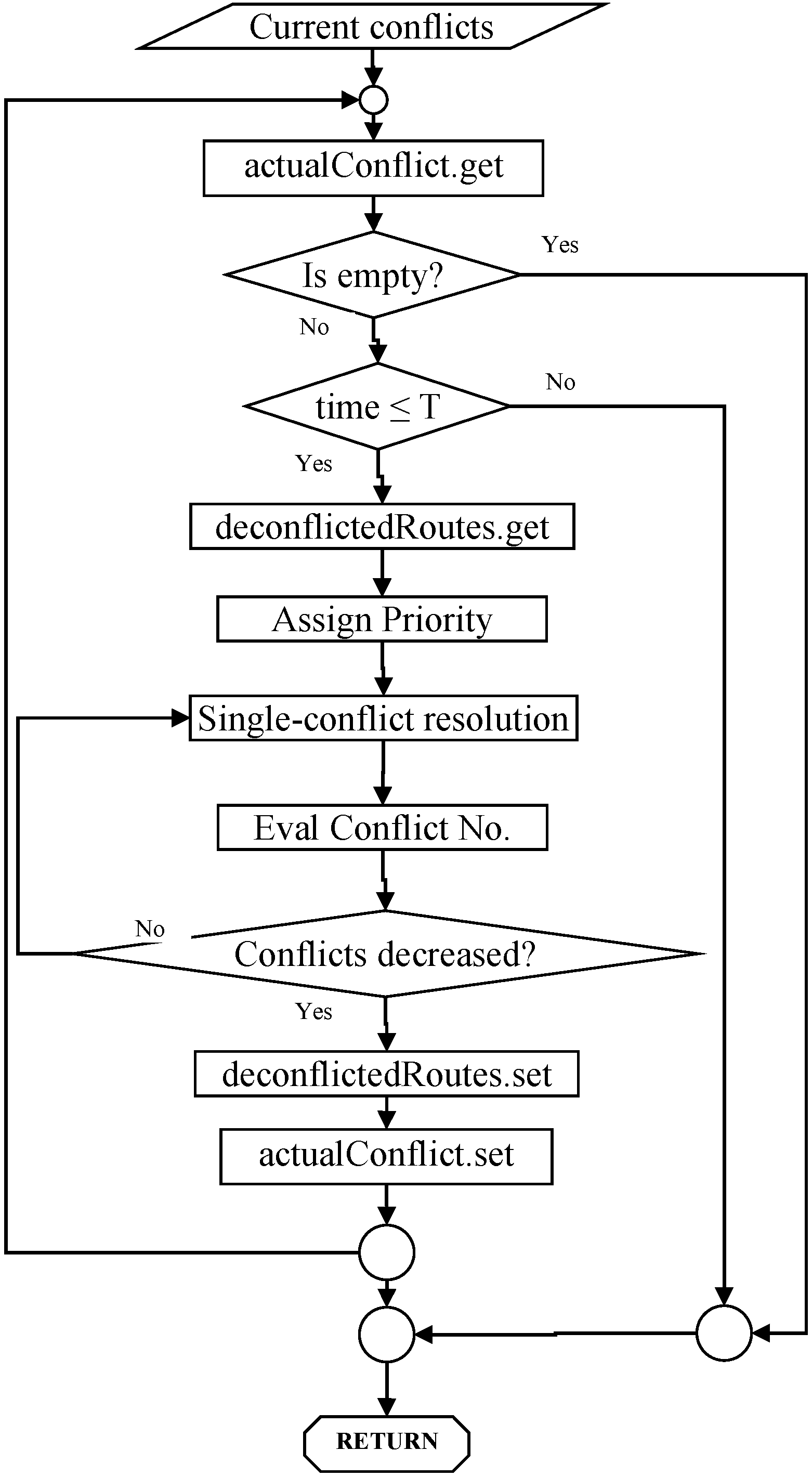
Analyzing the conflicts between individual pairs of aircraft has the advantage that the possible resolution maneuvers can be screened with limited computational load, especially if compared to a global conflict resolution strategy attempting to solve all (or most, at least) conflicts concurrently. With this single-conflict approach, however, care must be exercised in selecting a resolution maneuver that does not generate new conflicts with other aircraft. This is done in the current algorithm, checking that the resolution maneuver decreases the number of total conflicts. Because the resolution maneuver solves the conflict between the two aircraft under analysis by definition, requiring the number of total conflicts to decrease assures that the number of conflicts with all other aircraft does not increase. The overall strategy for managing the single-conflict approach is shown in
Figure 4. This flow diagram is based on assuming that a single-conflict resolution that is not increasing the number of other conflicts can always be found. This heuristic assumption imposes some specific requirements on the single-conflict resolution maneuver described in the next paragraph. Furthermore, the overall computational time is bounded by a pre-defined threshold, T, to cope with the previously discussed requirements. If this threshold is reached, a suboptimal solution will be output, in which only part of the conflicts are solved.
Figure 4.
Managing the single-conflict approach.
Figure 4.
Managing the single-conflict approach.
Single-conflict resolution can be achieved by three alternative maneuvers of the aircraft with lower priority:
Modifying its TSAT for outbound aircraft. Steps of Δs are selected up to the time that complies with both the TOBT and the take-off sequence defined by DMAN. Compliance is enforced with Δs tolerance.
Forbidding the vertex where the conflict occurs and re-computing the standalone solution;
Increasing the waiting time at holding points. Steps of Δs are selected also in this case.
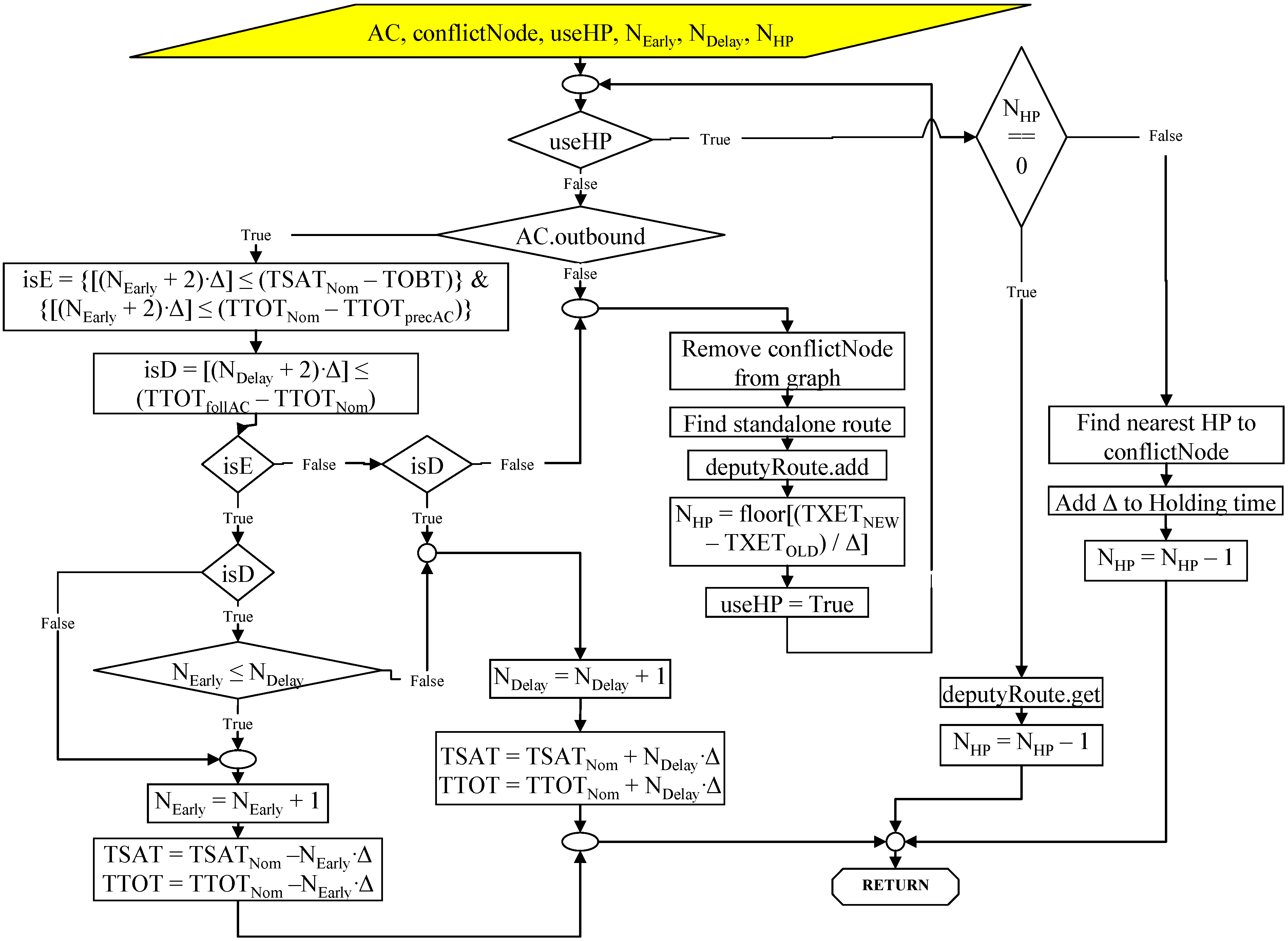
Solution 1 is preferable over the other two, because it does not increase the TXET, but only shifts the taxi route in time. Between Solutions 2 and 3, the one that induces the smaller increase is preferable. Solution 2 is executed only once and is checked for conflicts only after Solutions 3 with smaller delays is ascertained to yield a nuisance. Because of the overall conflict management, we assume that a single-conflict resolution that is not increasing the number of other conflicts can always be found by repeatedly applying Solution 3. In other terms, an aircraft may be asked to queue at a Holding Position (HP) until there is at least a 2Δ window between other aircraft crossing in front of the HP. The overall de-conflicting strategy is summarized in
Figure 5. Solution 1, being the most complicated of the three, is further discussed in the following paragraphs.
Figure 5.
De-conflicting strategy.
Figure 5.
De-conflicting strategy.
The conditions that allow modification of the TSAT from the nominal value, TSAT
Nom, shall consider the compliance of the new TSAT both with the aircraft TOBT and with the take-off sequence. The take-off sequence is fixed by a DMAN based on elements that XRP does not take into account and shall not be modified. Compliance with the take-off sequence implies, thus, that no aircraft may be allowed by XRP to take off, either after the following or before the preceding aircraft in the sequence. The compliance of the modified timed taxi route to these conditions shall be enforced with a tolerance of Δ, which yields:
In Equation (3), TSAT, TTOT and TOBT refer to the current aircraft,
i.e., the one that is being deconflicted, whilst TTOT
precAC refers to the TTOT of the aircraft preceding the current one in the take-off sequence, and TTOT
follAC refers to the TTOT of the aircraft following the current one in the take-off sequence. Equation (3) constrain the amount by which TSAT
Nom may be varied. Since Solution 1 modifies TSAT
Nom at steps of Δs, the amount of variation that can be applied to anticipate or delay an aircraft is given by:
where N
Early and N
Delay are the integer numbers of steps the aircraft being de-conflicted that have been anticipated and delayed, respectively. In fact, the de-conflicting logic may increase the amount of time an aircraft is anticipated or delayed, until either the conflict is solved or the aircraft cannot be further anticipated or delayed. This is equal to increasing the integer numbers, N
Early and N
Delay. In order to evaluate if a certain aircraft can be further delayed or anticipated, conditions (3) shall be checked against the amount of anticipation or delay one wishes to apply for solving the conflict.
Let us refer to the case of an aircraft being de-conflicted. Assume that anticipating this aircraft NEarly times and delaying it NDelay times has not yet solved the conflict. We wish to check if we can further anticipate or delay this aircraft for solving the conflict.
Consider first the anticipation case: this implies that we wish to check if the aircraft being de-conflicted can have a TSAT = TSAT
Nom − (N
Early + 1) Δ. The first and the second of conditions (3) shall be verified for increasing N
Early to N
Early + 1. These can be combined in a Boolean flag, isE, which is a necessary condition for further anticipating the aircraft,
i.e., N
Early = N
Early + 1, as follows:
Consider, now, the delay case: this implies that we wish to check if the aircraft being de-conflicted can have a TSAT = TSAT
Nom + (N
Delay + 1) Δ. Only the third condition in Equation (3) applies. A Boolean flag, isD, is introduced, also, in this case, being a necessary condition for further delaying the aircraft,
i.e., N
Delay = N
Delay + 1, as follows:
5. Example Application to Rome Ciampino Airport
The airport information needed to support the development of the route planner can be summarized in the below reported list:
Runway(s) in use for arrivals and departures;
Length, maximum allowed wingspan, maximum allowed aircraft gross weight for each taxiway;
Location of crossroads between two taxiways;
Holding points on taxiways;
Special rules for taxiway use in particular conditions, such as wet ground, poor visibility and daytime restrictions.
This information is available via the Air National Service Provider in charge of the airport ATCo, e.g., Ente Nazionale Assistenza al Volo (ENAV) S.p.a. for Italian airports, which is thus responsible for maintaining the Integrated Aeronautical Information Package document conforming to applicable international standards [
13].
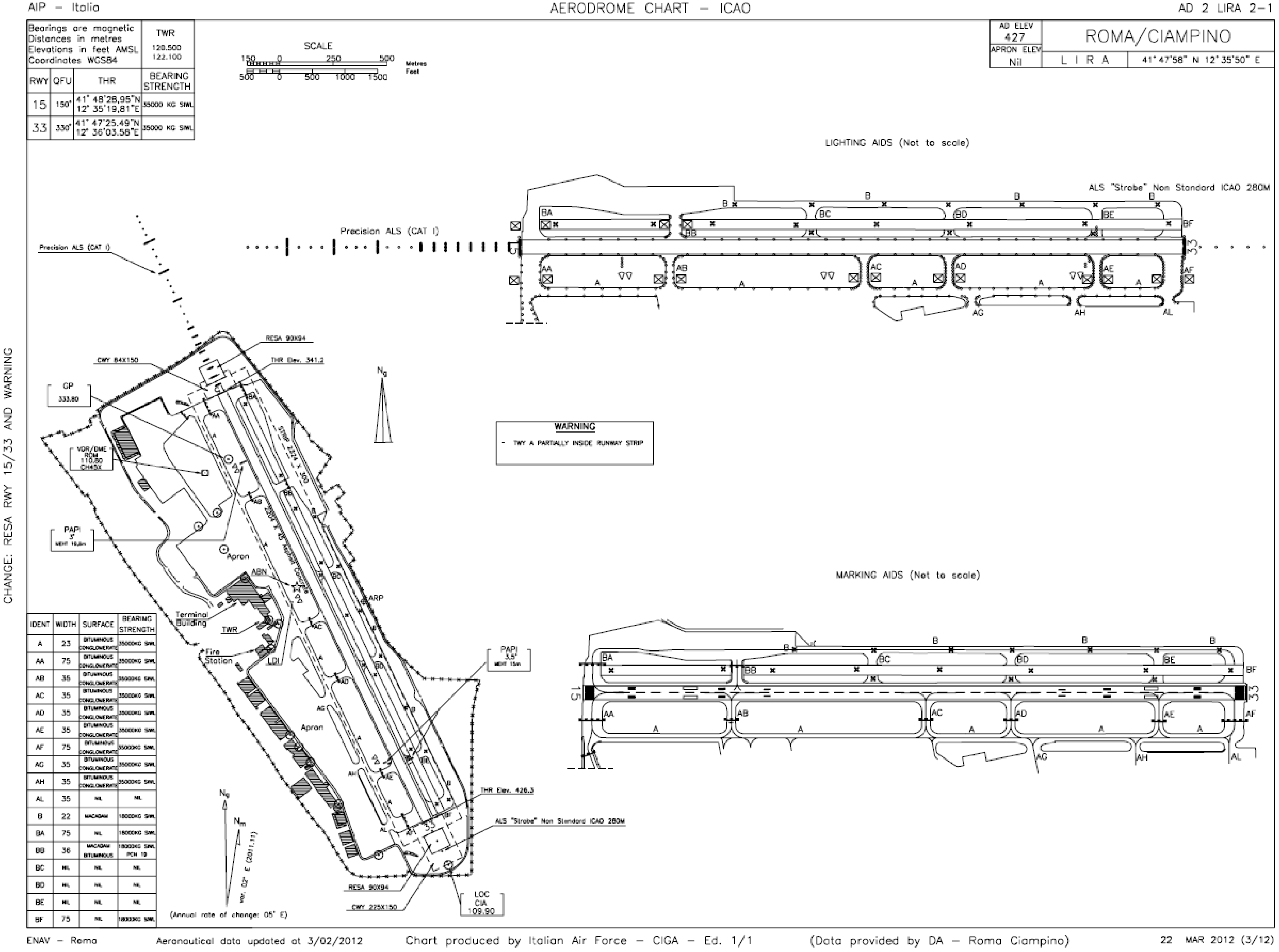
Figure 6 shows the aerodrome chart of the Rome Ciampino airport (International Civil Aviation Organization (ICAO) code LIRA), publicly made available by ENAV in the Italian Aeronautical Information Publication [
14]. LIRA airport is selected in this paper only for validation and illustrative purposes, the target airports for the deployment of advanced airport operation concepts being substantially bigger and more complex. Nonetheless, LIRA is a good compromise for initial testing of the algorithm, as well as for understanding the issues in modeling an airport for XRP.
Figure 6.
LIRA aerodrome chart (taken from [
14]).
Figure 6.
LIRA aerodrome chart (taken from [
14]).
As reported in the first section of this report, a graph structure shall represent the graph to solve the shortest path problem. The type of graph shall be non-unidirectional, since some taxiways can be travelled in both ways, and weighted, since a distance is defined for each edge. Two separate graphs are built for computing the standalone shortest path solution, that is, one encoding the available paths for the aircraft at arrival and one for the aircraft at departure. The procedure that allows for building the two graphs consists of the following steps:
Identify all crossroads between at least two taxiways on the map. They will be the internal vertices of the graph;
Retrieve the distances between each pair of contiguous crossroads. Two crossroads are contiguous if they are on the same taxiway and there is no other crossroad between them;
Set a starting vertex on each runway/apron for arriving/departing aircraft;
Set an ending vertex on each apron/runway for arriving/departing aircraft;
Add an edge for each (portion of) taxiway that connects two vertices. The right way to travel the taxiway at departure/arrival shall be taken into account. Two edges shall be added if both ways are available;
Distances obtained at point 2 shall be associated with each edge introduced at point 5;
The maximum aircraft wingspan allowed for each taxiway shall be associated with the relevant edges;
The maximum aircraft reference mass allowed for each taxiway shall be associated with the relevant edges;
Taxiways that cannot be travelled in special weather, visibility and daytime conditions must be noted to insert the proper graph forbidden states in the tool.
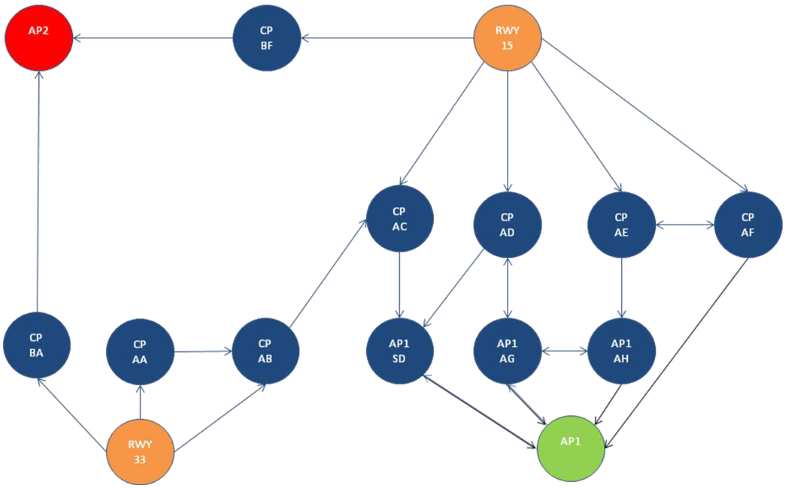
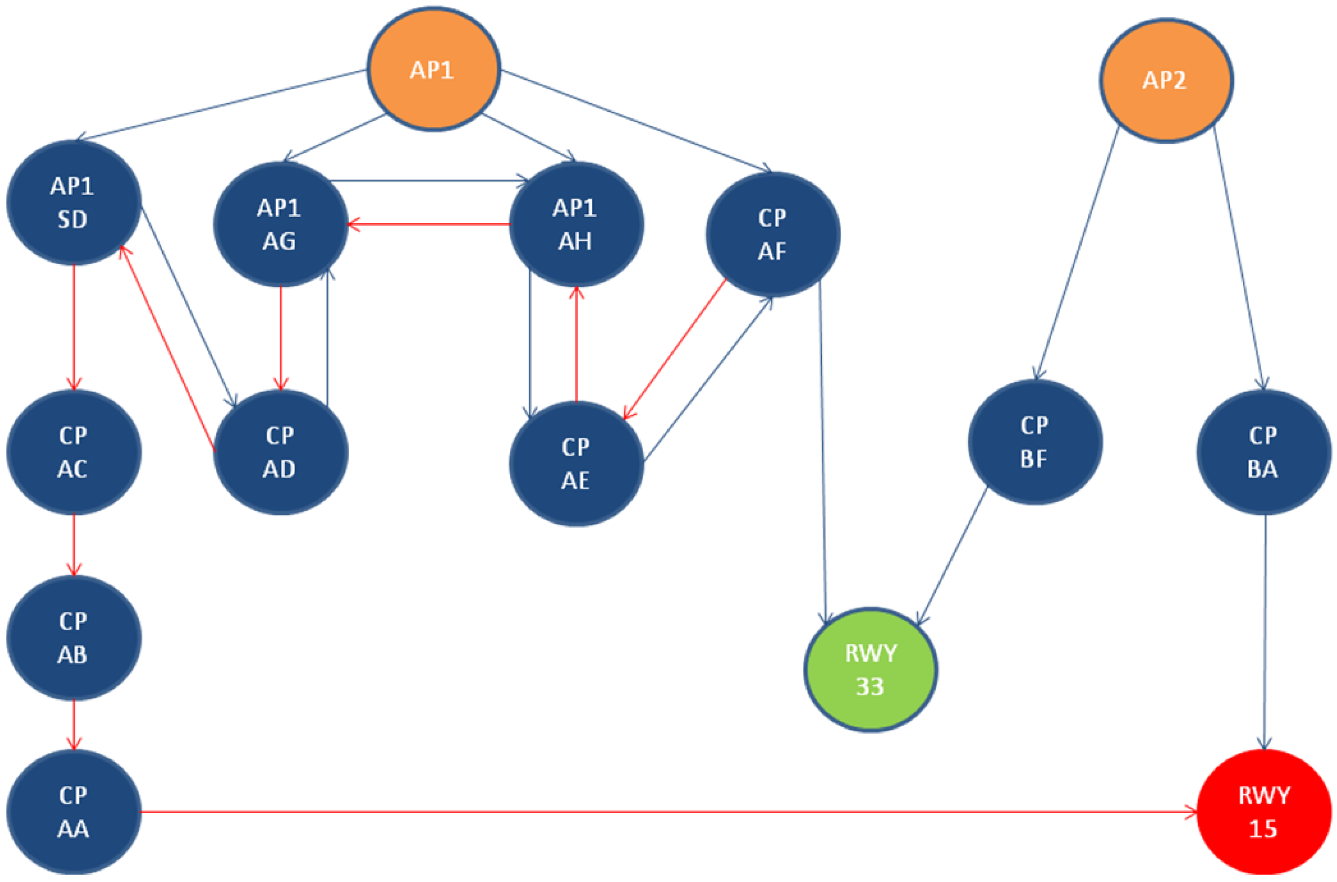
Following this procedure, arrival and departure graphs can be easily built for Rome Ciampino airport and are shown in
Figure 7. Source vertices are colored in orange, taxiways crossroads and holding positions are drawn in blue and the end vertices are in red and green. The vertices are labeled using the same nomenclature used in [
14], making the resulting graph easily understandable by comparing
Figure 7 with LIRA data.
Figure 7.
LIRA airport coding onto arrival (top) and departure (bottom) graphs for XRP.
Figure 7.
LIRA airport coding onto arrival (top) and departure (bottom) graphs for XRP.
7. Conclusions
A novel algorithm has been presented, aimed at safely and optimally managing the routing of aircraft on an airport surface in future airport operations envisioned by the SESAR project. A reference scenario has been defined for taking into account the features of future airport operations that are relevant to aircraft taxi routing and planning. Target operational requirements are laid out for developing the routing algorithm. Constraints have been identified, and route optimality has been defined based on the minimization of the time the aircraft spends on the airport surface with engines on.
The proposed algorithm first computes a standalone, shortest path solution from runway to apron or vice versa, depending on the aircraft being inbound or outbound, respectively. The presence of other aircraft on the airport surface is neglected at this stage. For taking into account the constraints due to other traffic on the airport surface, this solution is amended by a conflict detection and resolution task that attempts to reduce and possibly nullify the number of conflicts generated in the first phase. The conflict resolution makes use of the prioritization of aircraft in conflict and chooses the conflict resolution that allows for the minimum increase of the taxi time.
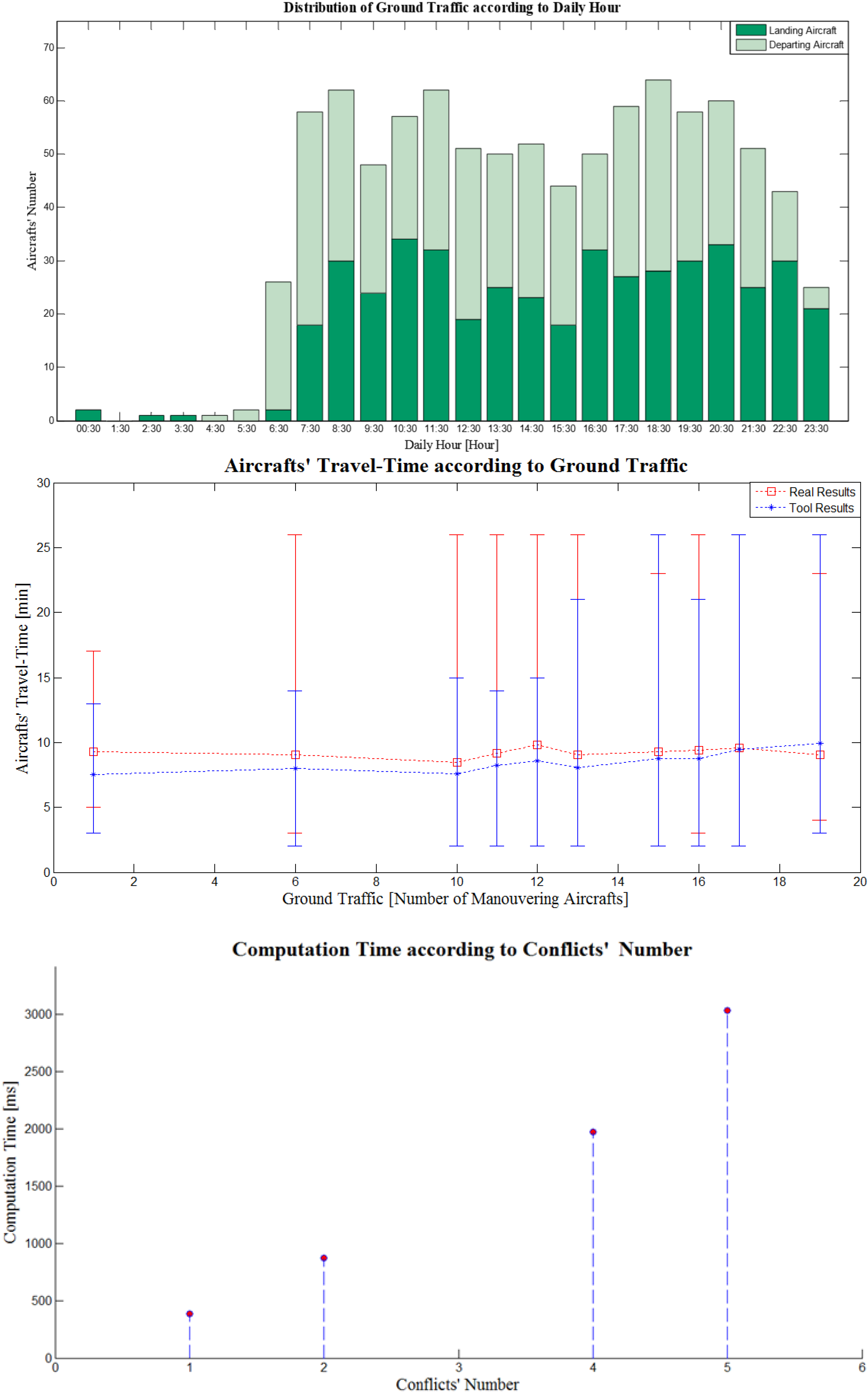
An example application on a simple Italian airport exemplifies how the algorithm can be applied to true-world applications. Emphasis is given on how to model the airport surface as a weighted and directed graph with non-negative weights, as required for the input to the algorithm. A preliminary performance assessment is also presented on a hypothetical airport representing an Italian hub. Results suggest that the algorithm concept is capable of coping with heavy traffic levels. Future work will be concerned with evaluation of the algorithm’s performances on the actual aircraft data of an Italian hub.


 ,
, 
