Achievement of Automatic Copper Wire Elongation System


Department of Electronic Engineering, National Chin-Yi University of Technology, Taichung 41170, Taiwan
*
Author to whom correspondence should be addressed.
Algorithms 2019, 12(5), 105; https://doi.org/10.3390/a12050105
Submission received: 17 April 2019
/
Revised: 11 May 2019
/
Accepted: 13 May 2019
/
Published: 15 May 2019
(This article belongs to the Special Issue Selected Papers from the 15th International Conference on Automation Technology)
Abstract
:Copper wire is a major conduction material that carries a variety of signals in industry. Presently, automatic wire elongating machines to produce very thin wiresare available for manufacturing. However, the original wires for the elongating process to thin sizes need heating, drawing and then threadingthrough the die molds by the manpower before the machine starts to work. This procedure repeatsuntil the wire threads through all various die molds. To replace the manpower, this paper aims to develop an automatic wire die molds threading system for the wire elongation process. Three pneumatic grippers are designed in the proposed system. The first gripper is used to clamp the wire. The second gripper fixed in the rotating mechanism is to draw the heated wire. The third gripper is used to move the wire for threading through the dies mold. The force designed for drawing the wire can be adjusted via the gear ratio. The experimental results confirm that the proposed system can accomplish the wiredies mold threading processin term of robustness, rapidness and accuracy.
1. Introduction
Automation on demand for all technical processes is essential in industry. However, the variety of desired functionalities makes the automation system extremely varied. As a result, the modern automation systems are moving towards very high complexity. A high degree of automation increases requirements in measurement technology and goes on in automation technology such as closed-loop and open-loop control or others. Feasible application-specific methods for signal measurement to master future systems are thus indispensable [1,2,3,4,5,6]. Unfortunately, the wire threading through the die mold for theelongation process has not been automatizeduntil now [7,8,9,10]. For advanced automation study related to this issue, many papers can be found in the literature [11,12,13,14,15,16,17,18]. Nevertheless, the design of wire die mold threading automation can be regarded as a new technological development in the copper wire manufacturing discipline.
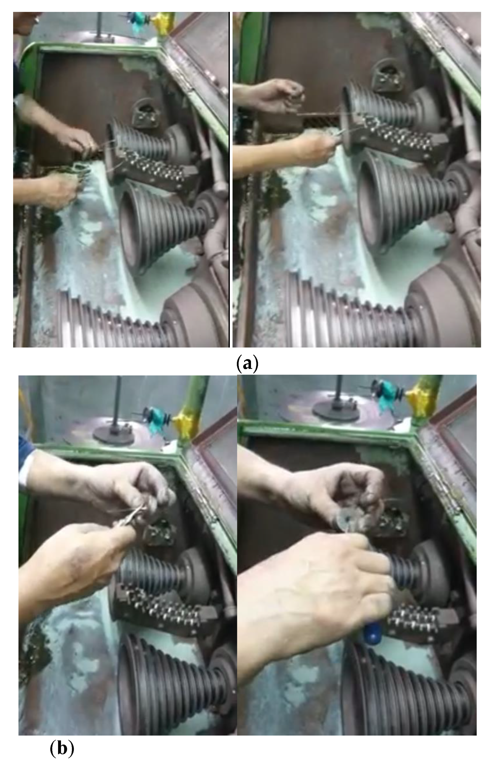
The 2.6 m/m oxygen-free copper is the original material for producing very thin wires. Applications include, for example, super thin medical cable, digestive system endoscopic ultrasound (EUS), and respiratory system EUS, etc. in the medical system. For these purposes, the 2.6 m/m wire must be elongated sufficiently to a small size like 0.05 m/m. Although there are machines available for the elongation process, currently the preparatory work still relies on human operation for the wire dies mold threading action. The whole procedure may take at least 30 minutes prior to machine operation, shown in Figure 1.
2. Design Principle
Fundamental Concept
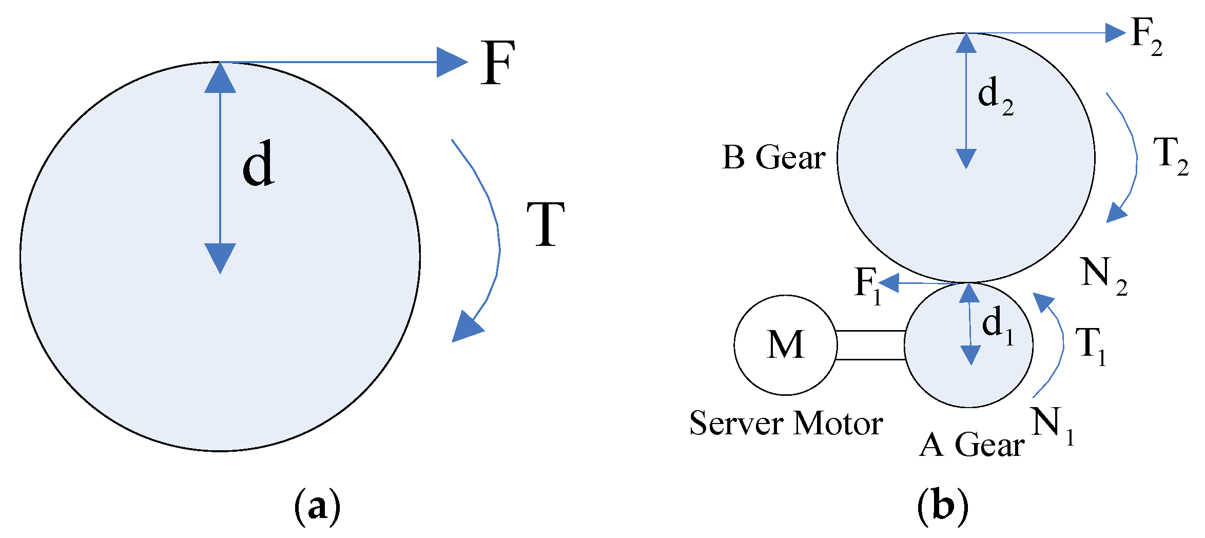
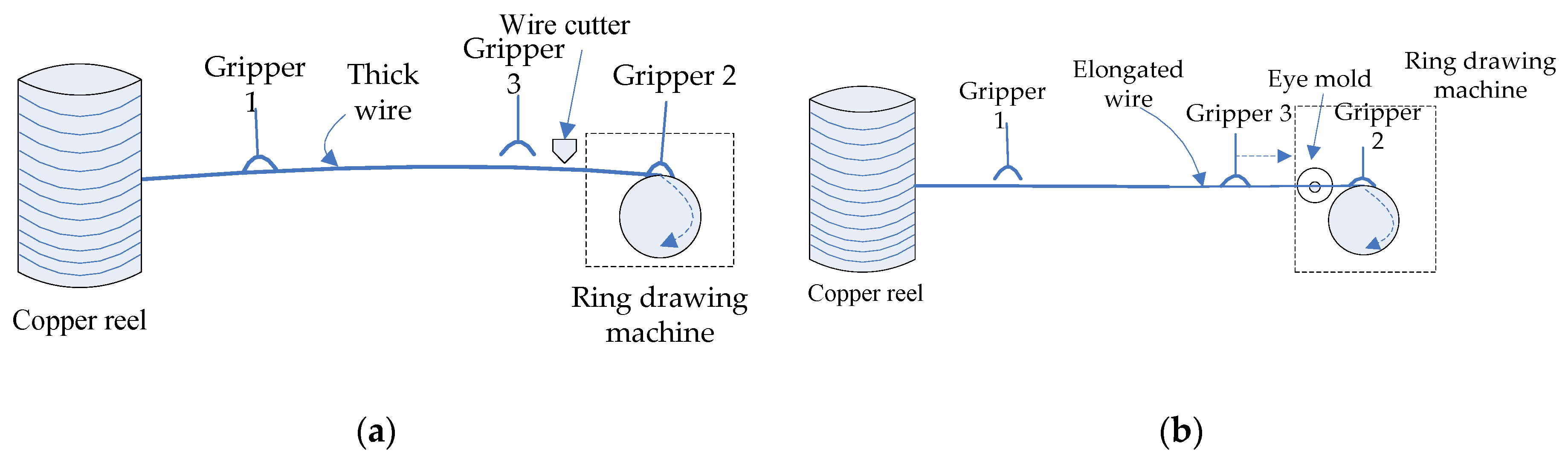
The proposed system is based on the ring drawing principle, demonstrated in Figure 2.
From Figure 2a, the torque is defined as
where T: torque, F: force, d: distance from the force to the axle center.
T = F · d,
By theory, the power output from the motor is equal to the power of gears A and B, respectively.
It can be rewritten as
where and are the angular frequency of gears A and B, respectively.
As above, it is clear that the force is the key factor for the wire elongation. It indicates that increasing the force can strengthen the torque. In other words, will result in and thus is enlarged.
3. System Structure
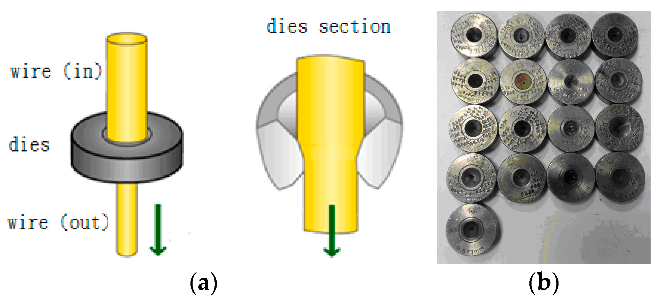
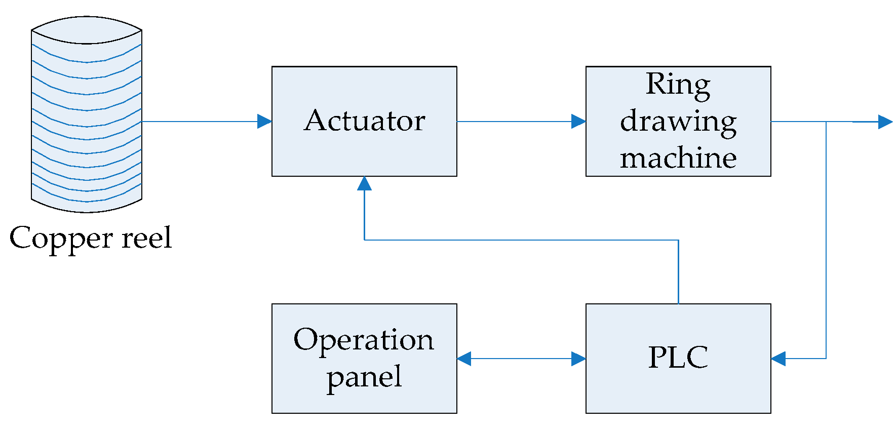
The dies mold used to elongate the copper wire from a wide diameter into a small size is shown in Figure 3. The proposed system structure is shown in Figure 4. It mainly contains (1) copper reel provides the copper wire for elongation; (2) actuator integrates gripper, heater, server motor, cutter and pneumatic cylinder; (3) ring drawing machine supplies necessary power to elongate the wire; (4) Programmable Logic Controller (PLC) is the core controller; (5) operation panel provides a friendly human–machine interface. The profile of elongating wire and dies mold threading are shown in Figure 5a,b, respectively.
4. Design of Mechanical System
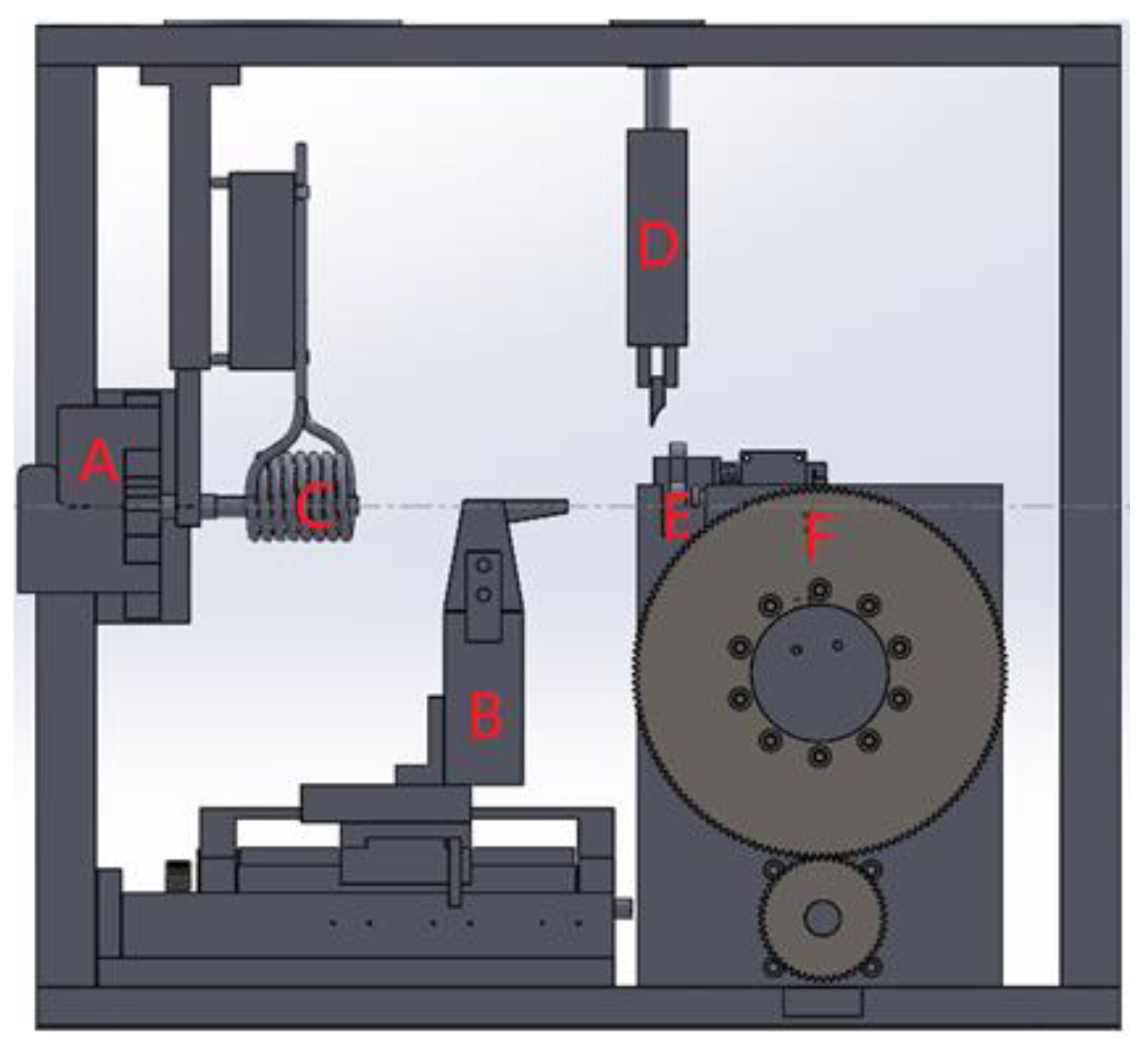
The major mechanical blocks of the proposed system, shown in Figure 6, include A: gripper 1. B: contactless heater. C: gripper 3. D: wire cutter. E: dies mold. F: ring drawing machine (including the server motor with gripper 2).
Based on the concept of the above theory, a 30 kg weightwas designed to elongate the copper wire. Selecting the mechanical system parameters is shown as follows.
, , = 0.03125 m, = 0.09375 m, = 30 kgw = 30 × 9.8 N = 294 N.
Assume
According to Equation (4), the motor power should be selected larger thanthe following value.
In this case, a 400 W server motor with rating torque: 1.27 is used in this system.
5. System Implementation with Experimental Results
5.1. Description of System Implementation
Based on the system design shown in Section 4, the implementation procedures apply to the real system, demonstrated as follows. Note that the left figure is the design diagram, and the right one is itsrespective real mechanism for every step.
Step 1: The wire was moved to the ring drawing machine through gripper 2.![Algorithms 12 00105 i001]()

Step 2: the wireswereclamped down by grippers 1 and 2 simultaneously, and then the copper wire wassoftened for seconds by the heater.

Step 3: the heating process stopped, and the wire wasdrawn for elongation by the ring drawing machine.

Step 4:gripper 1 opened.

Step 5: the elongated wire wasmoved to the cutter by the ring drawing machine.

Step 6: grippers 1 and 3 clipped the wire, and the cutter cut the wire.

Step 7: The cut wire wasdelivered forward a certain distance for falling down whengripper 2 opens.

Step 8: gripper 2 moved back to the starting location.

Step 9: the dies moldwasplaced.

Step 10: gripper 1 opened.

Step 11: gripper 3 movedfor wire threading through the dies mold.

Step 12: gripper 1 opened.

Step 13: gripper 2 clipped, and gripper 3 opened.

Step 14: The wire waselongatedcontinuously until the desired length wasreached.

5.2. Experimental Results
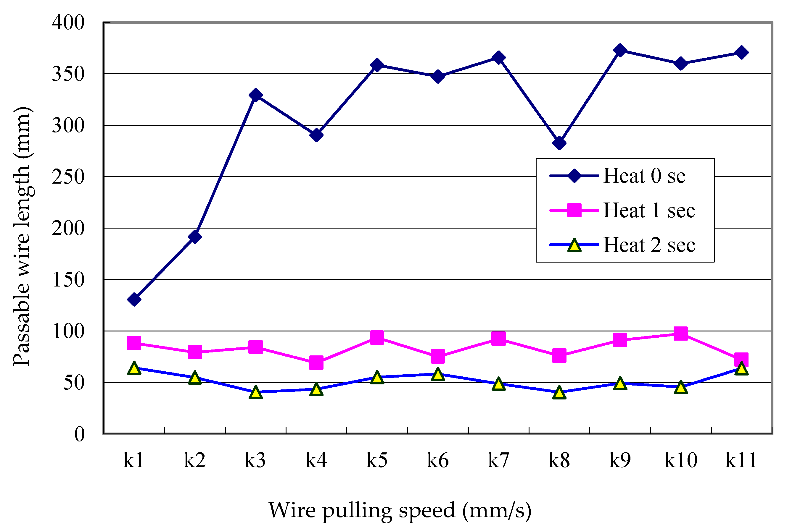
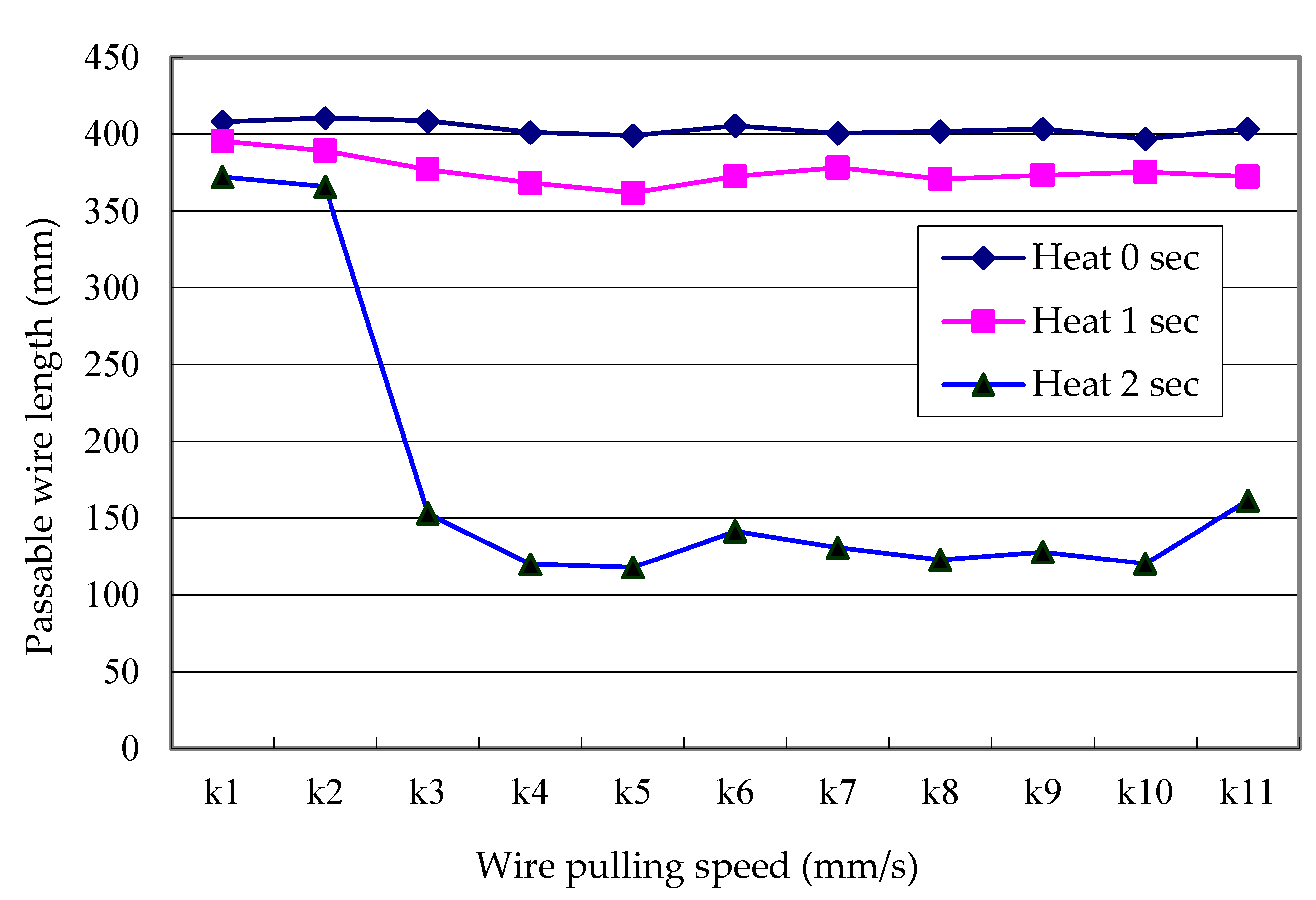
To verify the effectiveness of the proposed system, two kinds of copper wire diameters, i.e., 0.3 mm and 0.6 mm, have been tested using various wire pulling speeds and different heating time (0–2 s). Every test was carried out three times under the same conditions. The experimental data, as shown in Table 1, Table 2, Table 3, Table 4, Table 5, Table 6, Table 7, Table 8, Table 9, Table 10, Table 11, Table 12, Table 13, Table 14, Table 15, Table 16, Table 17, Table 18, Table 19, Table 20, Table 21 and Table 22, includes (1) passable wire length for threading through dies mold, (2) wire elongating length, (3) operation time. Note that the temperature of heating time using 0 s, 1 s, 2 s was 25.5°, 28.5° and 38°, respectively.
Case 1: copper wire diameter: 0.3 mm
Case 2: Copper wire diameter: 0.6 mm
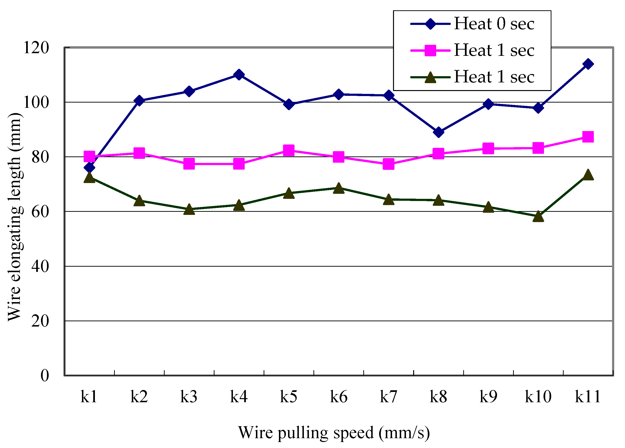
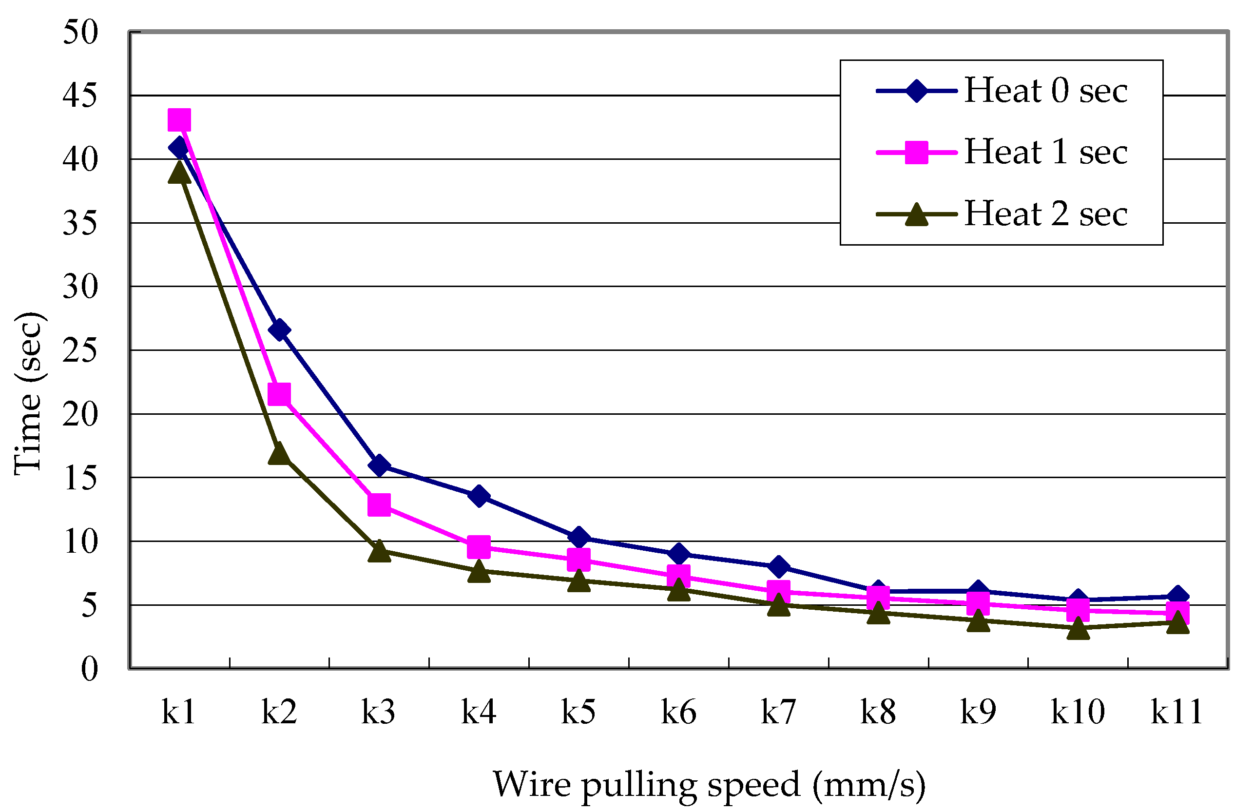
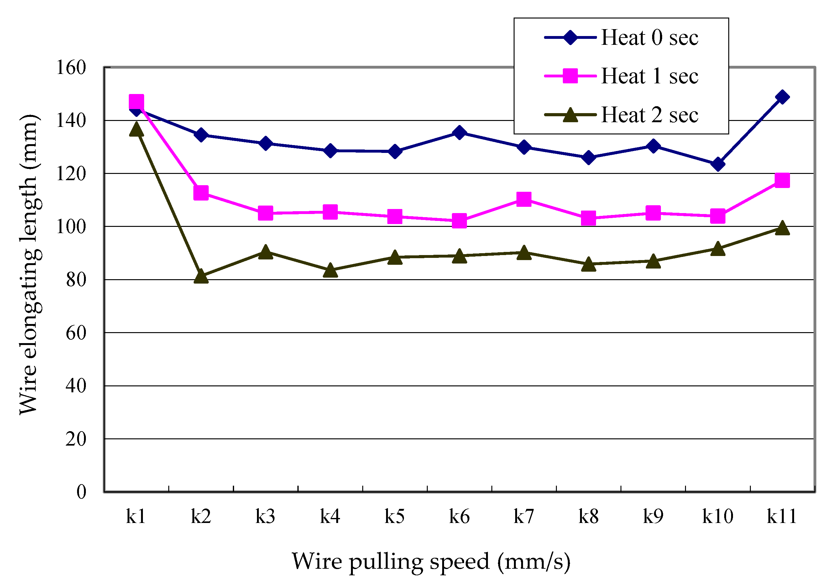
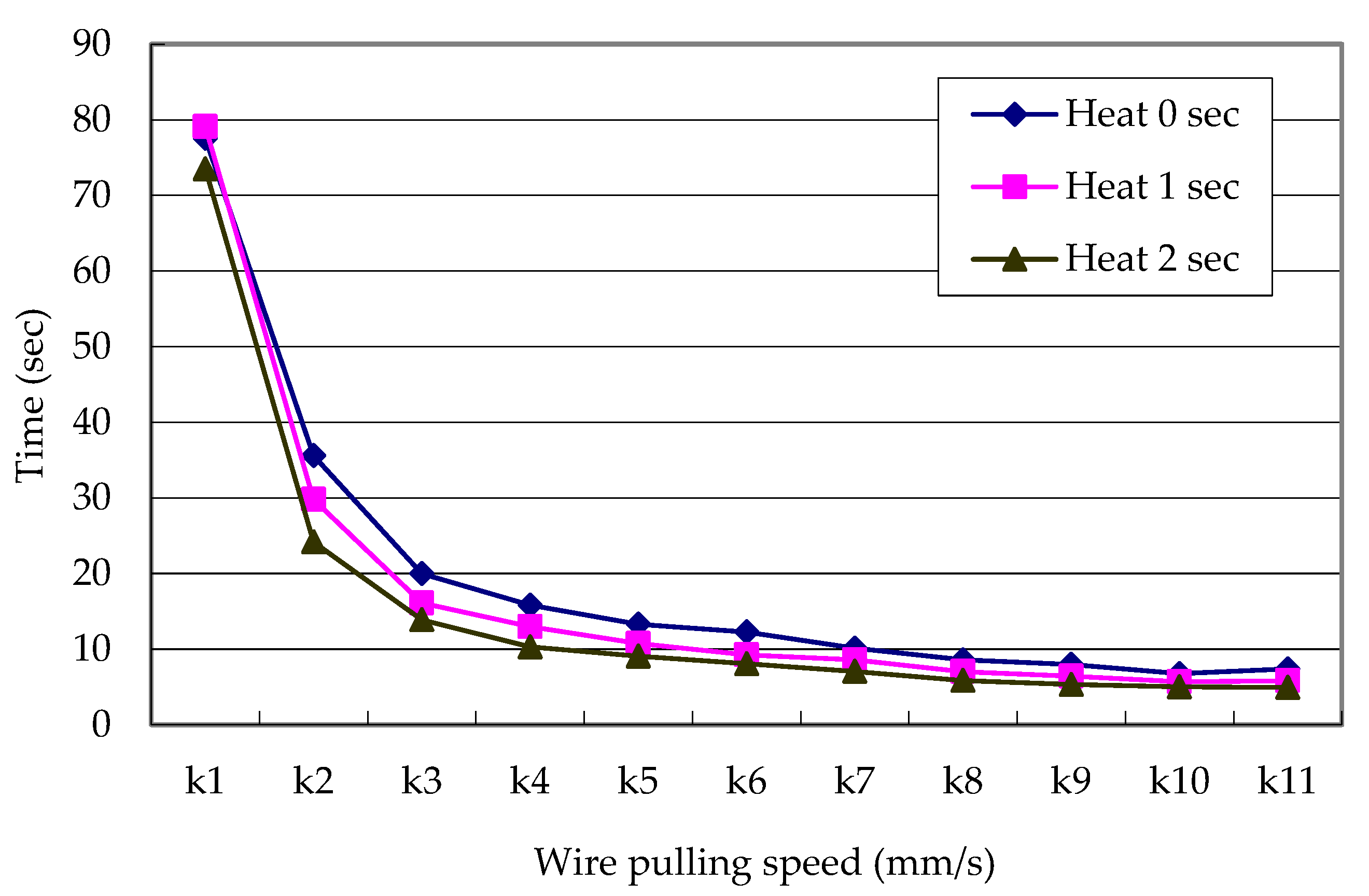
Above results based on average test data can be concluded from Figure 7, Figure 8, Figure 9, Figure 10, Figure 11 and Figure 12. The passable wire length vs. wire pulling speed for 0.3 mm and 0.6 mm wires at different heating period (0–3 s) are shown in Figure 7 and Figure 8, respectively. The wire elongating length and time vs. wire pulling speed for the 0.3 mm wire at different heating period (0–3s) are shown in Figure 9 and Figure 10, respectively. The wire elongating length and time vs. wire pulling speed for 0.6 mm wire at different heating period (0–3 s) are shown in Figure 11 and Figure 12, respectively. Some key outcomes are listed as follows.
- For both 0.3 mm and 0.6 mm wires, the wire pulling speed didnot affect the passable wire length significantly. However, longer heating period, e.g., 2 s, decreased the passable wire length and wire elongating length considerably due to the wire being easily broken by the heating.
- The wire elongating time for 0.3 mm wasshorter than 0.6 mm one. In other words, a wider diameter wire required a longer elongating time.
- Increasing heating period resulted in a relatively shorter wire elongating time. It indicates that the temperature didinfluence the wire elongating time.
6. Conclusions
The demand fora variety of thin copper wires is now increasing considerably in different precision electronic instruments. However, the traditional thin wire manufacturing machinesstill require the manpower to thread the wire through die molds for prolongation before entering the automatic process. Itusually takes at least 2 min for each dies moldwire threading. Contrastively, the proposed algorithm has proposed a new algorithm to reduce the process timeonly taking about45 s, relatively much shorter than the traditional method using manpower. Consequently, it can be applied directly to the current machines formore efficient performance.Moreover, it can reach the following achievements:
- Automatic wire dies mold threading capability for wire elongation.
- We had wire rotation during the drawingprocess.
- Wire elongation up to 140 mm for 0.6 mm wire and 100 mm for 0.3 mm wire without broken line.
- Adjustable wire drawing speed.
- Suitability for a variety of wire size elongation.
Additionally, the experimental results suggest that it is unnecessary to use a heater if the wire drawing power is sufficient unless the wire is broken during the process. Also, the wire pulling speed may be chosen as fast as possible. However, the strength and friction of grippers 1 and 3 should be taken account to avoid wire slipping.
Author Contributions
H.-C.L. proposed the idea and wrote this paper. C.-H.C. carried out the experiments and collected the data.
Funding
This research was funded by Ministry of Science and Technology, Taiwan, grant number MOST 107-2637-E-167-002.
Acknowledgments
The authors are grateful to Ministry of Science and Technology, Taiwan, for sponsoring the project.
Conflicts of Interest
The authors declare no conflict of interest.
References
- Shin, S. Trend of Process Automation and Factory Automation. In Proceedings of the 2006 SICE-ICASE International Joint Conference, Busan, Korea, 18–21 October 2006. [Google Scholar]
- Lin, H.C.; Hsiao, K.C. Integration of DC circuit breaker and fault current limiter based on zero-voltage resonant switching approach. IET Circuits Devices Syst. 2019, 13, 344–351. [Google Scholar] [CrossRef]
- Zhou, C.; Huang, S.; Xiong, N.; Yang, S.; Li, H.; Qin, Y.; Li, X. Design and Analysis of Multimodel-Based Anomaly Intrusion Detection Systems in Industrial Process Automation. IEEE Trans. Syst. Man Cybern. Syst. 2015, 45, 1345–13660. [Google Scholar] [CrossRef]
- Jiao, Z.-J.; He, C.-Y.; Wang, J.; Zhao, Z. Development and application of automation control system to plate production line. In Proceedings of the 2010 11th International Conference on Control Automation Robotics & Vision, Singapore, 7–10 December 2010. [Google Scholar]
- Merdan, M.; Lepuschitz, W.; Axinia, E. Advanced process automation using automation agents. In Proceedings of the 5th International Conference on Automation, Robotics and Applications, Wellington, New Zealand, 6–8 December 2011. [Google Scholar]
- Yang, Z.-Y.; Li, H. Design of automatic assembly tire machine. In Proceedings of the 2011 International Conference on Intelligent Materials, Applied Mechanics and Design Science, IMAMD2011, Beijing, China, 24–25 December 2011; pp. 99–102. [Google Scholar]
- Mahapatra, A.; Patkar, U.S.; Lanjewar, R.W.; Roy, S.S. Design of an automatic parallel type jute bag making machine. Indian J. Fibre Text. Res. (IJFTR) 2008, 33, 93–96. [Google Scholar]
- Fan, H.-C.; Yi, X.-H.; Cheng, X.-M.; Zhu, Y.-F. Automaticwool washingmachinedesign and research. In Proceedings of the 2011 International Conference on Mechanics and Manufacturing Systems, ICMMS 2011, Ningbo, China, 13–14 November 2011; pp. 377–380. [Google Scholar]
- Lin, J.-C.; Tai, J.-C.; Huang, H.-H. Design and manufacture of anautomaticwrappingmachine. In Proceedings of the 1995 International IEEE/IAS Conference on Industrial Automation and Control: Emerging Technologies, Taipei, Taiwan, 22–27 May 1995; pp. 698–701. [Google Scholar]
- Deng, Y.-C.; Yu, M.; Chen, H. Design of automatic buckle machine for double bag packaging line. In Proceedings of the 4th International Conference on Advances in Materials and Manufacturing, ICAMMP 2013, Kunming, China, 18–19 December 2013; pp. 303–308. [Google Scholar]
- Wang, Y.-X.; Zhao, C.-F. A novel design of a digital and automatic winding machine control system. In Proceedings of the 2011 International Conference on Mechatronics and Intelligent Materials, MIM 2011, Lijiang, China, 21–22 May 2011; pp. 581–584. [Google Scholar]
- Li, A.-M.; Zhang, C.-H.; Li, H.-L.; Xu, Z.-Y.; Chen, X.-H.; Qin, G.-L.; Ye, S.-W. Design of automatic welding machine based on PLC. In Proceedings of the 2011 4th International Conference on Intelligent Computation Technology and Automation, ICICTA 2011, Shenzhen, China, 28–29 March 2011; pp. 627–630. [Google Scholar]
- Gilbert, G.; Kuperman, A.; Sobel, L. Design of the man-machine interface for an automatic target user system. In Proceedings of the IEEE 1992 National Aerospace and Electronics Conference, Dayton, OH, USA, 18–22 May 1992; Volume 2, pp. 691–697. [Google Scholar]
- Tang, S.C.; Yao, J.M.; Zhu, S.X.; Wang, M.S.; Fang, J.N.; Taoll, X.H. Design of the Control system for Fully Automatic Steel-tube Molding Machine. In Proceedings of the 2014 Fifth International Conference on Intelligent Systems Design and Engineering Applications (ISDEA), Zhangjiajie, China, 15–16 June 2014; pp. 393–397. [Google Scholar]
- Bhaskarwar, T.V.; Giri, S.S.; Jamakar, R.G. Automation of shell and tube type heat exchanger with PLC and LabVIEW. In Proceedings of the 2015 International Conference on Industrial Instrumentation and Control (ICIC), Pune, India, 28–30 May 2015; pp. 841–845. [Google Scholar]
- Maraba, V.A.; Kucuoglu, A.E. PID Neural Network Based Speed Control of Asynchronous Motor Using Programmable Logic Controller. Adv. Electr. Comput. Eng. 2011, 11, 23–28. [Google Scholar] [CrossRef]
- Roman, N.; Ceanga, E.; Bivol, I.; Caraman, S. Adaptive Automatic Gauge Control of a Cold Strip Rolling Process. Adv. Electr. Comput. Eng. 2010, 10, 7–17. [Google Scholar] [CrossRef]
- Yang, T.; Ji, X.-J.; Li, C.-J. Wrench assembly design in OpUs darwin SO (spray-off) automatic assembly machine. In Proceedings of the 2011 International Conference on Electric Information and Control Engineering (ICEICE), Wuhan, China, 15–17 April 2011; pp. 3799–3802. [Google Scholar]
Figure 1.
Human operation for wire dies mold treading. (a) Wire elongating process by hands; (b) wire treading dies mold.
Figure 1.
Human operation for wire dies mold treading. (a) Wire elongating process by hands; (b) wire treading dies mold.

Figure 2.
Relation of torque and gear. (a) Torque; (b) torque and gear.

Figure 3.
Profile of dies mold. (a) Dies; (b) dies molds.

Figure 4.
System structure.

Figure 5.
Profile of proposed system operation. (a) Profile of elongating wire; (b) profile of dies mold threading.
Figure 5.
Profile of proposed system operation. (a) Profile of elongating wire; (b) profile of dies mold threading.

Figure 6.
Depiction of proposed mechanical system.

Figure 7.
Passable wire length vs. wire pulling speed for the 0.3 mm wire at different heating periods.
Figure 7.
Passable wire length vs. wire pulling speed for the 0.3 mm wire at different heating periods.

Figure 8.
Passable wire length vs. wire pulling speed for the 0.6 mm wire at different heating periods.
Figure 8.
Passable wire length vs. wire pulling speed for the 0.6 mm wire at different heating periods.

Figure 9.
Wire elongating length vs. wire pulling speed for the 0.3 mm wire at different heating periods.
Figure 9.
Wire elongating length vs. wire pulling speed for the 0.3 mm wire at different heating periods.

Figure 10.
Wire elongating time vs. wire pulling speed for the 0.3 mm wire at different heating periods.
Figure 10.
Wire elongating time vs. wire pulling speed for the 0.3 mm wire at different heating periods.

Figure 11.
Wire elongating length vs. wire pulling speed for 0.6 mm wire at different heating period.
Figure 11.
Wire elongating length vs. wire pulling speed for 0.6 mm wire at different heating period.

Figure 12.
Wire elongating time vs. wire pulling speed for the 0.6 mm wire at different heating periods.
Figure 12.
Wire elongating time vs. wire pulling speed for the 0.6 mm wire at different heating periods.


Table 1.
Results based on wire pulling speed: k1(1.86 m/s).
| Heating Time (s) | Passable Wire Length for Threading Dies Mold (mm) | Wire Pulling Length by the Ring Drawing Machine (mm)/Time (s) | ||||||
|---|---|---|---|---|---|---|---|---|
| 1st | 2nd | Third | Avg. | 1st | 2nd | Third | Avg. | |
| 0 | 148.5 | 138.76 | 133.27 | 130.68 | 80.07/43.05 | 74.73/40.18 | 73.39/39.46 | 76.06/40.9 |
| 1 | 85.98 | 81.87 | 96.65 | 88.17 | 72.06/38.75 | 88.08/47.35 | 80.07/43.05 | 80.07/43.05 |
| 2 | 60.94 | 65.21 | 66.64 | 64.26 | 72.06/38.74 | 73.39/39.46 | 72.06/38.75 | 72.50/38.98 |
Table 2.
Results based on wire pulling speed: k2(3.78 mm/s).
| Heating Time (s) | Passable Wire Length for Threading Dies Mold (mm) | Wire Pulling Length by the Ring Drawing Machine (mm)/Time (s) | ||||||
|---|---|---|---|---|---|---|---|---|
| 1st | 2nd | Third | Avg. | 1st | 2nd | Third | Avg. | |
| 0 | 163.72 | 235.23 | 175.49 | 191.48 | 93.42/24.71 | 106.76/28.24 | 101.42/26.83 | 100.53/26.59 |
| 1 | 74.7 | 81.31 | 81.96 | 79.32 | 81.14/21.47 | 82.74/21.89 | 80.07/21.18 | 81.32/21.51 |
| 2 | 69.37 | 49.06 | 46.21 | 54.88 | 68.86/18.22 | 61.39/16.24 | 61.65/16.31 | 63.97/16.92 |
Table 3.
Results based on wire pulling speed: k3(6.52 mm/s).
| Heating Time (s) | Passable Wire Length for Threading Dies Mold (mm) | Wire Pulling Length by the Ring Drawing Machine (mm)/Time (s) | ||||||
|---|---|---|---|---|---|---|---|---|
| 1st | 2nd | Third | Avg. | 1st | 2nd | Third | Avg. | |
| 0 | 283.83 | 342.13 | 361.38 | 329.11 | 96.08/14.74 | 106.76/16.37 | 108.89/16.70 | 103.91/15.94 |
| 1 | 86.85 | 81.61 | 84.05 | 84.17 | 88.07/13.51 | 80.07/12.28 | 82.74/12.69 | 77.4/12.83 |
| 2 | 46.12 | 38.69 | 37.34 | 40.72 | 66.66/10.01 | 62.45/9.58 | 53.38/8.19 | 60.83/9.26 |
Table 4.
Results based on wire pulling speed: k4(8.13 mm/s).
| Heating Time (s) | Passable Wire Length for Threading Dies Mold (mm) | Wire Pulling Length by the Ring Drawing Machine (mm)/Time (s) | ||||||
|---|---|---|---|---|---|---|---|---|
| 1st | 2nd | Third | Avg. | 1st | 2nd | Third | Avg. | |
| 0 | 205.2 | 285.72 | 379.95 | 290.29 | 112.09/13.79 | 108.09/13.29 | 109.96/13.53 | 110.05/13.54 |
| 1 | 67.38 | 70.94 | 68.91 | 69.08 | 74.73/9.19 | 77.40/9.52 | 80.07/9.85 | 77.4/9.52 |
| 2 | 37.97 | 49.19 | 43.42 | 43.53 | 61.39/7.55 | 63.26/7.78 | 62.45/7.68 | 62.37/7.67 |
Table 5.
Results based on wire pulling speed: k5(9.65 mm/s).
| Heating Time (s) | Passable Wire Length for Threading Dies Mold (mm) | Wire Pulling Length by the Ring Drawing Machine (mm)/Time (s) | ||||||
|---|---|---|---|---|---|---|---|---|
| 1st | 2nd | Third | Avg. | 1st | 2nd | Third | Avg. | |
| 0 | 362.71 | 348.64 | 363.9 | 358.42 | 107.02/11.09 | 101.95/10.56 | 88.61/9.18 | 99.19/10.28 |
| 1 | 85.89 | 90.11 | 104.44 | 93.48 | 74.73/7.74 | 85.40/8.85 | 86.74/8.99 | 82.29/8.53 |
| 2 | 56.93 | 63.11 | 45.47 | 55.17 | 66.72/6.91 | 68.06/7.05 | 65.39/6.78 | 66.72/6.91 |
Table 6.
Results based on wire pulling speed: k6(11.04 mm/s).
| Heating Time (s) | Passable Wire Length for Threading Dies Mold (mm) | Wire Pulling Length by the Ring Drawing Machine (mm)/Time (s) | ||||||
|---|---|---|---|---|---|---|---|---|
| 1st | 2nd | Third | Avg. | 1st | 2nd | Third | Avg. | |
| 0 | 350.16 | 328.05 | 363.61 | 347.27 | 102.46/9.31 | 96.08/8.70 | 109.96/8.95 | 102.83/8.99 |
| 1 | 75.75 | 80.72 | 69.07 | 75.18 | 78.74/7.13 | 84.34/7.64 | 76.60/6.94 | 79.89/7.24 |
| 2 | 53.85 | 66.36 | 54.67 | 58.29 | 67.53/6.11 | 70.46/6.38 | 67.79/6.14 | 68.59/6.21 |
Table 7.
Results based on wire pulling speed: k7(12.83 mm/s).
| Heating Time (s) | Passable Wire Length for Threading Dies Mold(mm) | Wire Pulling Length by the Ring Drawing Machine (mm)/Time (s) | ||||||
|---|---|---|---|---|---|---|---|---|
| 1st | 2nd | Third | Avg. | 1st | 2nd | Third | Avg. | |
| 0 | 349.57 | 372.26 | 375.2 | 365.67 | 98.75/7.69 | 106.22/8.28 | 102.46/8.01 | 102.48/7.99 |
| 1 | 88.5 | 93.62 | 94.79 | 92.3 | 73.93/5.76 | 74.73/5.82 | 83.27/6.49 | 77.31/6.02 |
| 2 | 47.75 | 55.55 | 43.32 | 48.87 | 62.45/4.87 | 70.73/5.51 | 60.05/4.68 | 64.41/5.02 |
Table 8.
Results based on wire pulling speed:k8(14.66 mm/s).
| Heating Time (s) | Passable Wire Length for Threading Dies Mold (mm) | Wire Pulling Length by the Ring Drawing Machine (mm)/Time (s) | ||||||
|---|---|---|---|---|---|---|---|---|
| 1st | 2nd | Third | Avg. | 1st | 2nd | Third | Avg. | |
| 0 | 291.32 | 242.93 | 313.37 | 282.54 | 90.75/6.19 | 90.75/6.19 | 85.41/5.83 | 88.97/6.07 |
| 1 | 69.7 | 84.39 | 73.72 | 75.94 | 81.14/5.53 | 81.40/5.55 | 80.87/5.51 | 81.14/5.53 |
| 2 | 35.55 | 39.12 | 47.13 | 40.6 | 62.45/4.26 | 61.65/4.21 | 68.33/4.66 | 64.14/4.38 |
Table 9.
Results based on wire pulling speed: k9(16.32 mm/s).
| Heating Time (s) | Passable Wire Length for Threading Dies Mold (mm) | Wire Pulling Length by the Ring Drawing Machine (mm)/Time (s) | ||||||
|---|---|---|---|---|---|---|---|---|
| 1st | 2nd | Third | Avg. | 1st | 2nd | Third | Avg. | |
| 0 | 364.46 | 374.8 | 378.74 | 372.67 | 99.29/6.08 | 105.16/6.44 | 93.42/5.73 | 99.29/6.08 |
| 1 | 83.88 | 99.91 | 89.5 | 91.1 | 75.53/4.63 | 92.08/5.64 | 81.40/4.98 | 83.0/5.08 |
| 2 | 51.52 | 49.43 | 46.92 | 49.29 | 61.39/3.76 | 60.85/3.73 | 62.72/3.84 | 61.65/3.78 |
Table 10.
Results based on wire pulling speed: k10(18.25 mm/s).
| Heating Time (s) | Passable Wire Length for Threading Dies Mold (mm) | Wire Pulling Length by the Ring Drawing Machine (mm)/Time (s) | ||||||
|---|---|---|---|---|---|---|---|---|
| 1st | 2nd | Third | Avg. | 1st | 2nd | Third | Avg. | |
| 0 | 328.16 | 375.626 | 375.8 | 359.87 | 96.08/5.26 | 98.21/5.38 | 99.28/5.44 | 97.86/5.36 |
| 1 | 97.44 | 95.02 | 99.67 | 97.38 | 83.01/4.55 | 83.54/4.58 | 83.01/4.55 | 83.19/4.56 |
| 2 | 40.68 | 46.05 | 50.23 | 45.65 | 58.18/3.19 | 56.31/3.09 | 60.32/3.30 | 58.27/3.19 |
Table 11.
Results based on wire pulling speed: k11(20.15 mm/s).
| Heating Time (s) | Passable Wire Length for Threading Dies Mold (mm) | Wire Pulling Length by the Ring Drawing Machine (mm)/Time (s) | ||||||
|---|---|---|---|---|---|---|---|---|
| 1st | 2nd | Third | Avg. | 1st | 2nd | Third | Avg. | |
| 0 | 374.19 | 369.4 | 368.37 | 370.65 | 111.56/5.54 | 116.64/5.79 | 113.69/5.64 | 113.96/5.66 |
| 1 | 73.86 | 72.44 | 70.01 | 72.1 | 93.41/4.64 | 86.21/4.28 | 82.21/4.08 | 87.28/4.33 |
| 2 | 69.71 | 60.37 | 61.47 | 63.85 | 76.60/3.80 | 68.86/3.42 | 74.99/3.72 | 73.48/3.64 |
Table 12.
Results based on wire pulling speed: k1(1.86 m/s).
| Heating Time (s) | Passable Wire Length for Threading Dies Mold (mm) | Wire Pulling Length by the Ring Drawing Machine (mm)/time (s) | ||||||
|---|---|---|---|---|---|---|---|---|
| 1st | 2nd | Third | Avg. | 1st | 2nd | Third | Avg. | |
| 0 | 417.02 | 415.98 | 390.81 | 407.94 | 156.64/84.37 | 158.54/85.23 | 117.17/62.99 | 144.12/77.53 |
| 1 | 394.89 | 390.52 | 400.38 | 395.26 | 155.87/83.80 | 130.25/70.03 | 155.07/83.37 | 147.06/79.07 |
| 2 | 367.91 | 373.76 | 374.78 | 372.15 | 130.25/70.02 | 148.66/79.93 | 131.31/70.59 | 136.74/73.51 |
Table 13.
Results based on wire pulling speed: k2(3.78 mm/s).
| Heating Time (s) | Passable Wire Length for Threading Dies Mold (mm) | Wire Pulling Length by the Ring Drawing Machine (mm)/Time (s) | ||||||
|---|---|---|---|---|---|---|---|---|
| 1st | 2nd | Third | Avg. | 1st | 2nd | Third | Avg. | |
| 0 | 414.56 | 404.02 | 412.74 | 410.44 | 138.25/36.58 | 128.11/33.89 | 137.19/36.29 | 134.52/35.59 |
| 1 | 402.71 | 382.82 | 381.77 | 389.1 | 116.90/30.93 | 113.17/29.94 | 107.83/28.53 | 112.63/29.8 |
| 2 | 368.37 | 354.87 | 374.22 | 365.82 | 91.10/24.08 | 91.55/24.22 | 91.55/24.22 | 81.4/24.17 |
Table 14.
Results based on wire pulling speed: k3(6.52 mm/s).
| Heating Time (s) | Passable Wire Length for Threading Dies Mold (mm) | Wire Pulling Length by the Ring Drawing Machine (mm)/Time (s) | ||||||
|---|---|---|---|---|---|---|---|---|
| 1st | 2nd | Third | Avg. | 1st | 2nd | Third | Avg. | |
| 0 | 414.12 | 412.8 | 398.67 | 408.53 | 138.32/20.75 | 128.37/19.69 | 127.31/19.53 | 131.33/19.99 |
| 1 | 379.37 | 373.7 | 377.9 | 376.99 | 105.95/16.25 | 106.23/16.29 | 102.76/15.76 | 104.98/16.1 |
| 2 | 160.27 | 151.26 | 147.63 | 153.05 | 90.75/13.92 | 90.21/13.83 | 90.48/13.88 | 90.48/13.88 |
Table 15.
Results based on wire pulling speed: k4(8.13 mm/s).
| Heating Time (s) | Passable Wire Length for Threading Dies Mold (mm) | Wire Pulling Length by the Ring Drawing Machine (mm)/Time (s) | ||||||
|---|---|---|---|---|---|---|---|---|
| 1st | 2nd | Third | Avg. | 1st | 2nd | Third | Avg. | |
| 0 | 398.57 | 406.22 | 398.33 | 401.04 | 126.51/15.56 | 132.38/16.28 | 126.78/15.59 | 128.56/15.81 |
| 1 | 361.16 | 372.98 | 370.75 | 368.3 | 105.43/12.97 | 105.69/13.00 | 105.16/12.93 | 105.43/12.97 |
| 2 | 121.08 | 118.99 | 119.55 | 119.87 | 84.07/10.34 | 83.01/10.21 | 83.81/10.31 | 83.63/10.29 |
Table 16.
Results based on wire pulling speed: k5(9.65 mm/s).
| Heating Time (s) | Passable Wire Length for Threading Dies Mold (mm) | Wire Pulling Length by the Ring Drawing Machine (mm)/Time (s) | ||||||
|---|---|---|---|---|---|---|---|---|
| 1st | 2nd | Third | Avg. | 1st | 2nd | Third | Avg. | |
| 0 | 398.78 | 401.97 | 395.41 | 398.95 | 129.45/13.41 | 129.71/13.44 | 125.71/13.03 | 128.29/13.29 |
| 1 | 361.83 | 360.84 | 361.52 | 361.83 | 106.22/11.01 | 100.35/10.39 | 104.62/10.84 | 103.73/10.75 |
| 2 | 117.28 | 119.88 | 116.26 | 117.81 | 87.28/9.04 | 91.28/9.46 | 86.81/8.68 | 88.46/9.06 |
Table 17.
Results based on wire pulling speed: k6(11.04 mm/s).
| Heating Time (s) | Passable Wire Length for Threading Dies Mold (mm) | Wire Pulling Length by the Ring Drawing Machine (mm)/Time (s) | ||||||
|---|---|---|---|---|---|---|---|---|
| 1st | 2nd | Third | Avg. | 1st | 2nd | Third | Avg. | |
| 0 | 416.57 | 393.32 | 406.06 | 405.32 | 139.32/12.62 | 132.12/11.97 | 134.75/12.21 | 135.4/12.27 |
| 1 | 377.08 | 369.25 | 371.11 | 372.48 | 110.49/10.01 | 97.15/8.79 | 98.75/8.95 | 102.13/9.25 |
| 2 | 136.83 | 147.97 | 139.27 | 141.36 | 88.88/8.05 | 93.68/8.49 | 84.34/7.64 | 88.97/8.06 |
Table 18.
Results based on wire pulling speed: k7(12.83 mm/s).
| Heating Time (s) | Passable Wire Length for Threading Dies Mold (mm) | Wire Pulling Length by the Ring Drawing Machine (mm) | ||||||
|---|---|---|---|---|---|---|---|---|
| 1st | 2nd | Third | Avg. | 1st | 2nd | Third | Avg. | |
| 0 | 402.49 | 396.81 | 401.94 | 400.41 | 121.17/9.44 | 131.58/10.26 | 136.91/10.67 | 129.89/10.12 |
| 1 | 383.75 | 378.23 | 372.56 | 378.18 | 112.89/8.79 | 108.36/8.45 | 109.43/8.53 | 110.22/8.59 |
| 2 | 134.36 | 128.31 | 129.77 | 130.81 | 91.55/7.14 | 94.75/7.39 | 84.41/6.66 | 90.24/7.06 |
Table 19.
Results based on wire pulling speed: k8(14.66 mm/s).
| Heating Time (s) | Passable Wire Length for Threading Dies Mold (mm) | Wire Pulling Length by the Ring Drawing Machine (mm)/Time (s) | ||||||
|---|---|---|---|---|---|---|---|---|
| 1st | 2nd | Third | Avg. | 1st | 2nd | Third | Avg. | |
| 0 | 398.96 | 401.23 | 404.89 | 401.69 | 126.24/8.61 | 125.71/8.58 | 125.98/8.59 | 125.98/8.59 |
| 1 | 369.07 | 372.55 | 370.9 | 370.84 | 103.02/7.03 | 106.49/7.26 | 99.82/6.81 | 103.11/7.03 |
| 2 | 126.11 | 116.09 | 126.24 | 122.81 | 87.01/5.94 | 84.34/5.75 | 86.21/5.88 | 85.85/5.86 |
Table 20.
Results based on wire pulling speed: k9(16.32 mm/s).
| Heating Time (s) | Passable Wire Length for Threading Dies Mold (mm) | Wire Pulling Length by the Ring Drawing Machine (mm)/Time (s) | ||||||
|---|---|---|---|---|---|---|---|---|
| 1st | 2nd | Third | Avg. | 1st | 2nd | Third | Avg. | |
| 0 | 403.73 | 406.41 | 399.23 | 403.12 | 131.85/8.08 | 132.38/8.11 | 126.78/7.77 | 130.34/7.99 |
| 1 | 375.64 | 375.34 | 368.61 | 373.2 | 104.36/6.37 | 108.03/6.62 | 102.76/6.3 | 105.05/6.43 |
| 2 | 134.39 | 126.63 | 122.47 | 127.83 | 89.95/5.51 | 85.94/5.27 | 85.14/5.22 | 87.01/5.33 |
Table 21.
Results based on wire pulling speed: k10(18.25 mm/s).
| Heating Time (s) | Passable Wire Length for Threading Dies Mold (mm) | Wire Pulling Length by the Ring Drawing Machine (mm)/Time (s) | ||||||
|---|---|---|---|---|---|---|---|---|
| 1st | 2nd | Third | Avg. | 1st | 2nd | Third | Avg. | |
| 0 | 395.4 | 395.41 | 399.68 | 396.83 | 126.24/6.92 | 121.97/6.68 | 122.24/6.7 | 123.48/6.77 |
| 1 | 368.48 | 381.79 | 375.79 | 375.35 | 103.02/5.64 | 106.23/5.82 | 102.49/5.62 | 103.91/5.69 |
| 2 | 121.1 | 114.24 | 125.54 | 120.29 | 90.21/4.94 | 85.14/4.67 | 99.82/5.47 | 91.72/5.02 |
Table 22.
Results based on wire pulling speed: k11(20.15 mm/s).
| Heating Time (s) | Passable Wire Length for Threading Dies Mold (mm) | Wire Pulling Length by the Ring Drawing Machine (mm)/Time (s) | ||||||
|---|---|---|---|---|---|---|---|---|
| 1st | 2nd | Third | Avg. | 1st | 2nd | Third | Avg. | |
| 0 | 400.74 | 402.02 | 407.25 | 403.34 | 143.86/7.14 | 151.84/7.54 | 150.8/7.48 | 148.83/7.39 |
| 1 | 374.86 | 366.09 | 376.16 | 372.37 | 117.44/5.83 | 116.1/5.76 | 118.50/5.88 | 117.35/5.82 |
| 2 | 160.99 | 167.27 | 155.8 | 161.35 | 97.95/4.86 | 99.82/4.95 | 100.89/5.01 | 99.55/4.94 |
© 2019 by the authors. Licensee MDPI, Basel, Switzerland. This article is an open access article distributed under the terms and conditions of the Creative Commons Attribution (CC BY) license (http://creativecommons.org/licenses/by/4.0/).
Share and Cite
MDPI and ACS Style
Lin, H.-C.; Cheng, C.-H. Achievement of Automatic Copper Wire Elongation System. Algorithms 2019, 12, 105. https://doi.org/10.3390/a12050105
AMA Style
Lin H-C, Cheng C-H. Achievement of Automatic Copper Wire Elongation System. Algorithms. 2019; 12(5):105. https://doi.org/10.3390/a12050105
Chicago/Turabian StyleLin, Hsiung-Cheng, and Chung-Hao Cheng. 2019. "Achievement of Automatic Copper Wire Elongation System" Algorithms 12, no. 5: 105. https://doi.org/10.3390/a12050105
Note that from the first issue of 2016, this journal uses article numbers instead of page numbers. See further details here.