Article

Optimized Sonar Broadband Focused Beamforming Algorithm

1
School of Marine Science and Technology, Northwestern Polytechnical University, Xi’an 710072, Shanxi, China
2
School of Electronic Engineering, Xi’an Aeronautical University, Xi’an 710077, Shaanxi, China
*
Author to whom correspondence should be addressed.
Algorithms 2019, 12(2), 33; https://doi.org/10.3390/a12020033
Submission received: 27 November 2018 / Revised: 25 January 2019 / Accepted: 31 January 2019 / Published: 5 February 2019

Abstract

:
Biases of initial direction estimation and focusing frequency selection affect the final focusing effect and may even cause algorithm failure in determining the focusing matrix in the coherent signal–subspace method. An optimized sonar broadband focused beamforming algorithm is proposed to address these defects. Initially, the robust Capon beamforming algorithm was used to correct the focusing matrix, and the broadband signals were then focused on the optimal focusing frequency by the corrected focusing matrix such that the wideband beamforming was transformed into a narrowband problem. Finally, the focused narrowband signals were beamformed by the second-order cone programming algorithm. Computer simulation results and water pool experiments verified that the proposed algorithm provides a good performance.

1. Introduction

Beamforming can obtain array directivity in a predetermined direction, and it can improve the signal-to-noise ratio of the received signal. Space interference is suppressed through spatial filtering. Beamforming can realize target bearing estimation for multiobject resolution. It has a significant role in the estimation of the target location, distance, and depth. It can also offer information for target recognition [1]. The narrowband signal contains minimal information about the targets, such that the broadband signal is chosen for parameter estimation, target detection, and feature extraction. Broadband signal beamforming processing has two methods: The incoherent signal–subspace method (ISM) and the coherent signal–subspace method (CSM). Compared with that of the ISM method, the focusing operation of the CSM algorithm can fully integrate the broadband information and make the covariance matrix of the focused signal keep full rank, thereby effectively solving the problem of broadband beamforming. The CSM algorithm has small computational complexity and high estimation precision; it can effectively overcome the problems in signal offset, extension, detection, and resolution threshold, and it can solve the multipath problem [2,3,4]. In the CSM algorithm, the broadband signal is first divided into several narrowband signals in different frequencies, and all the narrowband signals are then mapped to the same reference frequency by the focusing matrix, where the narrowband beamforming algorithm can be used to achieve broadband focused beamforming [5,6]. The structure of the focusing matrix is the core of the CSM algorithm, and the structure method of the focusing matrix plays a decisive role in the estimation of the performance of the CSM algorithm. The final focus effect in the estimation of the focusing matrix is determined by two factors: Initial direction estimation and focusing frequency choice. The deviation of these two factors would significantly decrease the final focusing effects, and it can even disable the algorithm. To solve this problem, the robust Capon beamforming (RCB) algorithm is used to correct the focusing matrix; it improves the focusing effect by considering the deviation of initial direction estimation [7,8,9]. The second-order cone programming (SOCP) method to compensate for the error of the focusing matrix was used in Reference [10]. However, neither of these methods considered the influence of the focusing frequency. In this paper, we propose an optimized sonar broadband focused beamforming algorithm. We used the RCB algorithm to correct the focusing matrix, and the focusing frequency problem was considered. The broadband signals were focused on the optimal focusing frequency by the corrected focusing matrix such that the wideband beamforming was transformed into a narrowband problem. Finally, the focused narrowband signals were beamformed by the second-order cone programming algorithm. The proposed method is derived in the next section. Section 3 reports simulation studies and performance analysis. Water pool experiments are reported in Section 4.

2. Broadband Focused Beamforming Algorithm

Let the incident signal be s ( t ) and the received broadband signal of the M array for:
x m ( t ) = s ( t τ m ) + n m ( t ) , m = = 1 , , M ,
where n m ( t ) is the additive noise of the m th array element, the output of each sensor is divided into K th non-overlapping blocks, and each block contains l sampling points. The FFT transform of L points is applied to each data block, the data in frequency domain is acquired from l frequency sub-bands, and each frequency sub-band contains a K data snapshot. The l th frequency sub-band data in the frequency domain represented in matrix form are:
X k ( f l ) = A l ( φ , θ ) s ( f l ) + n k ( f l ) , k = 1 , , K ; l = 1 , , L ,
where A l ( φ , θ ) is the steering vector of the l th frequency sub-band signal corresponding to the direction of ( φ , θ ) , φ is the pitching angle, and θ is the azimuth angle.
The focusing matrix should ensure the following equation is satisfied during focus transformation [10]:
T ( f j ) A ( f j , θ ) = A ( f 0 , θ ) , j = 1 , 2 , , J ,
where f j is any narrowband frequency within the scope of broadband, f 0 is the focusing frequency, A ( f j , θ ) is the steering vector of the j th frequency sub-band signal, and T ( f j ) is the focusing matrix.
In this paper, the focusing matrix was determined using the rotation signal subspace (RSS) method [11]. The optimal focusing matrix is determined by the following equation [10]:
{ min A ( f 0 , θ ) T ( f j ) A ( f j , θ ) F 2 ( j = 1 , 2 , , J ) T H ( f j ) T ( f j ) = I ,
where F is the Frobenius norm, and the solution of Equation (4) is:
T ( f j ) = V ( f j ) U H ( f j ) ( j = 1 , 2 , , J ) .
U ( f j ) and V ( f j ) are the left and the right singular vectors of the matrix A ( f j , θ ) A H ( f 0 , θ ) , respectively. The fitting errors still exist from the formula A ( f 0 , θ ) T ( f j ) A ( f j , θ ) F 2 , and the errors are associated with the focusing frequency.

2.1. Determination of Optimal Focusing Frequency

Equation (4) shows that the error can be obtained as follows [11]:
j J A ( f 0 , θ ) T ( f j ) A ( f j , θ ) F 2 = j J ( A ( f 0 , θ ) F 2 + A ( f j , θ ) F 2 2 Re { t r [ A ( f 0 , θ ) A H ( f j , θ ) T H ( f j ) ] } ) .
The direction matrix A ( f j , θ ) of an arbitrary shape array should satisfy the following condition:
A ( f j , θ ) F 2 = i = 1 P a ( θ ) F 2 = M P
where i ( i = 1 , 2 , , P ) is the number of signals. Take Equation (6) into Equation (5), then:
j J A ( f 0 , θ ) T ( f j ) A ( f j , θ ) F 2 = 2 J M P j = 1 J i = 1 P λ i [ A ( f 0 , θ ) A H ( f j , θ ) ] ,
where λ i [ A ( f 0 , θ ) A H ( f j , θ ) ] is the first P maximum singular value of the matrix A ( f 0 , θ ) A H ( f j , θ ) . Therefore, the value of j = 1 J i = 1 P λ i [ A ( f 0 , θ ) A H ( f j , θ ) ] must be maximized to minimize the focusing transform error.
Let:
F = max f 0 [ j = 1 J i = 1 P λ i [ A ( f 0 , θ ) A H ( f j , θ ) ] ] .
The focusing fitting error is minimized when F is maximized. For the direction matrix of any array, if the number of signals P is less than the number of array elements M, we may obtain:
i = 1 P λ i [ A ( f 0 , θ ) A H ( f j , θ ) ] i = 1 P λ i [ A ( f 0 , θ ) ] λ i [ A H ( f j , θ ) ] .
Let:
u i = j = 1 J λ i [ A ( f j , θ ) ] .
Then:
F max f 0 { i = 1 P λ i [ A ( f 0 , θ ) ] u i } .
From Equation (11), the focusing frequency f 0 , which is the optimal focusing frequency, is obtained. The time complexity of this algorithm is O ( n 3 ) .

2.2. Principle of an Optimized Broadband Focused Beamforming Algorithm

The correlation matrix estimated from the sample values in frequency domain is:
R l = 1 K k = 1 K X k ( f l ) X k H ( f l ) l = 1 , , L ,
where K is the data snapshot in each frequency sub-band and f 0 is the optimal focusing frequency according to the determination method. According to the given range of frequencies and optimal focusing frequency, the beamforming algorithm based on RCB becomes:
{ max a 0 σ 0 2 s u b j e c t t o R 0 σ 0 2 a 0 a 0 H 0 a n d a 0 a ¯ 0 2 ε ,
where σ 0 2 is the power of the optimal focusing frequency sub-band; R 0 and a 0 are the covariance matrix and the steering vector of the optimal focusing frequency sub-band, respectively; a ¯ 0 is presumed steering vector; and ε is the custom error range of steering vector. The correction vector is the closest to the real value as follows:
a ^ 0 = ( R 1 κ + I ) 1 a ¯ 0 = a ¯ 0 ( I + κ R ) 1 a ¯ 0 ,
where κ is determined by Newton iteration method [12,13]. The correction vector a ^ l of the other reference frequency can be determined. f l is the other reference frequency. The correction focusing matrix can be determined by the steering vectors a ^ 0 and a ^ l .
T ^ l ( φ , θ ) = V ^ ( f l ) U ^ H ( f l )
Each of the sub-band data is focused on the optimal frequency sub-band by the focusing matrix.
The focusing data of the l th frequency sub-band are [14]:
X ˜ ( f l ) = T ^ l ( φ , θ ) X ( f l ) = T ^ l ( φ , θ ) A l ( φ 0 , θ 0 ) s ( f l ) , + T ^ l ( φ , θ ) n ( f l )
where X ˜ ( f l ) for l = 1 , , L , and for each l , X ˜ ( f l ) is the narrowband signal [15]. The narrowband signals can be beamformed by second-order cone programming.
The robust low-sidelobe narrowband beamforming ensures that the response of the beam to the direction of observation is 1, and the sidelobe level is minimized. The weighted vector of beamforming should be constrained for beamforming robustness.
min W max | θ θ 0 | Δ | p ( θ ) | , s u b j e c t t o p ( θ 0 ) = 1 , W σ ,
where θ 0 is the observation direction, Δ is the half width of the main lobe, σ is the constraint limit of the weight vector norm, and y 1 is the nonnegative real variable. Let θ s be directions of the sidelobe for s = 1 , 2 , , S , Equation (17), which can be written as:
min y 1 , W y 1 , s u b j e c t t o V H ( θ 0 ) W = 1 ,   V H ( θ s ) W y 1 ( | θ s θ 0 | Δ , s = 1 , 2 , , S ) W σ .
Given the value of Δ , the vector y can be calculated through the above formula, and the weighted vector W is obtained.
Each of the sub-band weighted vectors is satisfied:
W l = W 0
The array output beam in frequencies f 0 and f l is:
p 0 ( φ , θ ) = | W 0 H A 0 ( φ , θ ) | ,
p l ( φ , θ ) = | W 0 H T ^ l ( φ , θ ) A l ( φ , θ ) | .
To make p 0 ( φ , θ ) equal to p l ( φ , θ ) ( l = 1 , , L ) , then:
| W 0 H A 0 ( φ , θ ) | = | W 0 H T ^ l ( φ , θ ) A l ( φ , θ ) | .
Therefore, the beam width formed by each narrow band beam is constant.
The most obvious benefit of the proposed method is the use of the advantages of the RCB algorithm and the SOCP method; at the same time, the optimal focusing frequency problem is considered.

3. Simulation and Performance Analysis

It is assumed that the incident signal is a wideband signal with a frequency range of 2250 Hz–3000 Hz. The bandwidth of this broadband signal is 750 Hz. A uniform circular array is built from 24 isotropic elements, and its radius is 0.5 m.

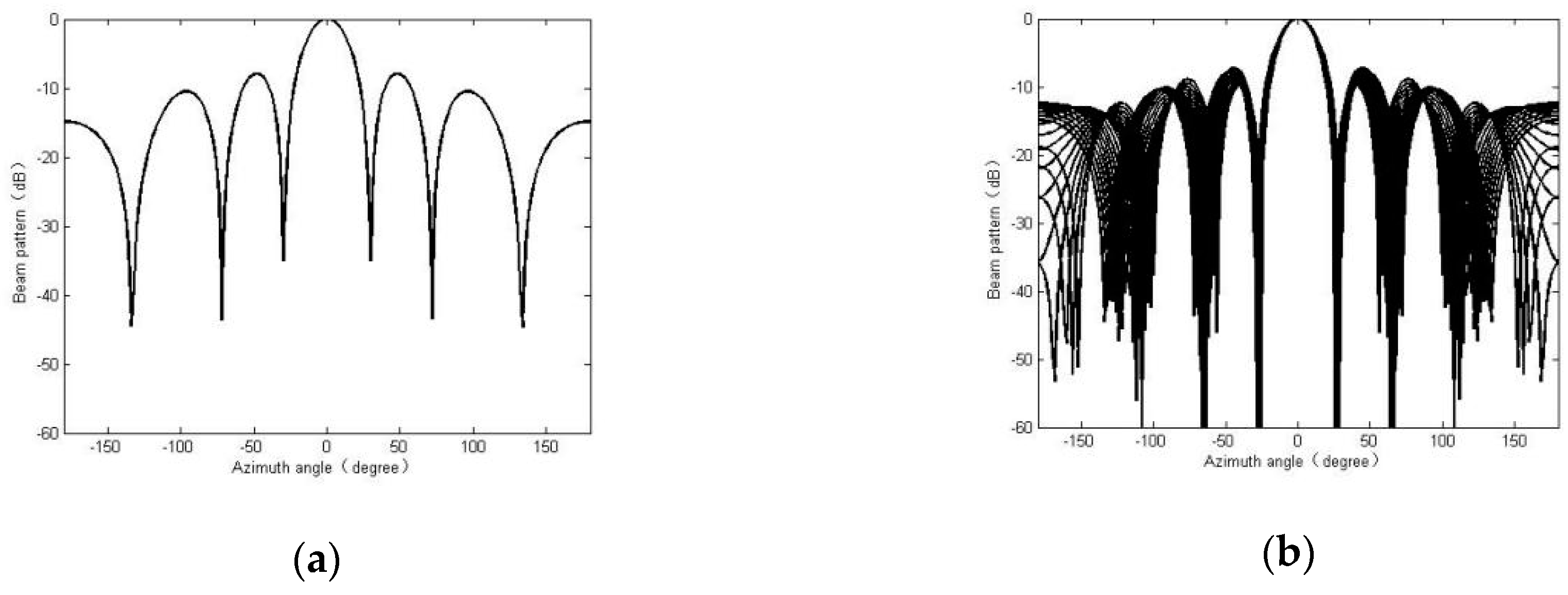
3.1. Validity Verification of the Optimal Focusing Frequency

Five group simulation experiments were conducted to verify the effectiveness of the best focusing frequency in broadband focusing beamforming. First, the broadband signal was divided into 21 sub-band signals through filtering or DFT processing. Second, the 21 sub-band signals were focused on 2250, 2450, 2900, 3000, and the optimal focusing frequency 2760 Hz, respectively, using the RSS algorithm. Next, the conventional delay-and-sum beamforming was used to achieve the constant beam width beamforming. The beam patterns on the different focusing frequencies are shown in Figure 1, Figure 2, Figure 3, Figure 4 and Figure 5. Figure 1a shows the narrowband signal beam with the frequency 2760 Hz using the conventional delay-and-sum beamforming method. Figure 1b shows the beam superposition graph of the broadband signal, whose frequency range is within 2250–3000 Hz using RSS. Figure 2, Figure 3, Figure 4 and Figure 5 show the simulation results on the focusing frequency of 2250, 2450, 2900, and 3000 Hz, respectively. Table 1 and Table 2 shows the comparison of beamforming parameters for narrowband signals and broadband signals. The comparison of beamforming parameter change between narrowband and broadband signals is shown in Table 3.
As shown in Table 1, Table 2 and Table 3, The effects of broadband beamforming at five focused frequencies were compared and analyzed from the main lobe width and the sidelobe level of the beam. The comparison results in Table 3 show that the main lobe width of the broadband focusing beam differs with its corresponding narrowband beam of 2.4°, and the sidelobe level of the broadband focusing beam differs with its corresponding narrowband beam of 0.17 dB. The simulation results with the selected focusing frequency less than 2760 Hz are shown in Figure 2 and Figure 3. The wideband and narrowband beams have poor consistency before and after focusing. The main lobe width of the wideband focusing beam can be kept consistent with each other. The main lobe width varies slightly, but the sidelobe level varies greatly, reaching 2 dB. The simulation results with the selected focusing frequency greater than 2760 Hz are shown in Figure 4 and Figure 5. The wideband beams are not consistent with the narrowband beams before and after focusing. The main lobe width of the wideband focusing beams can also be consistent, but the main lobe width varies greatly, reaching 3.1°; the sidelobe level varies greatly as well. Therefore, the broadband beam pattern focused on the optimal focusing frequency has an optimal effect.

3.2. Optimized Broadband Focused Beamforming Algorithm Based on RCB Algorithm

First, the RCB algorithm was used to correct the focus matrix. Second, the 21 sub-band signals were focused on the optimal focusing frequency 2760 Hz by the corrected focusing matrix T ^ ( f j ) . Finally, the conventional delay-and-sum beamforming can complete the constant beam-width beamforming. The time complexity of this algorithm is O ( n 3 ) .
Figure 6 shows the main lobe width of the broadband focusing beam is 21.4°, and the sidelobe level of the broadband focusing beam is 7.5 dB.
Compared to Figure 1b, a narrower main lobe is obtained, and it can keep the main lobe constant and make the sidelobe lower. Therefore, an optimized broadband focused beamforming algorithm based on the RCB algorithm is effective.

3.3. Optimized Sonar Broadband Focused Beamforming Algorithm

First, the 21 sub-band signals were focused on the optimal focusing frequency 2760 Hz by the focusing matrix corrected by the RCB algorithm. Then, the narrowband signals were beamformed by the SOCP algorithm. The time complexity of this algorithm is O ( n 3 ) .
Figure 7 shows the main lobe width of the broadband focusing beam is 19.3°, and the sidelobe level of the broadband focusing beam is 41.7 dB.
Compared to the above beam pattern, the broadband focused beam pattern with an optimized algorithm performs better. Water pool experiments were carried out to further verify the validity of the algorithm.

4. Water Pool Experiments

The algorithm in this paper was verified by pool experiments in an anechoic pool. The block diagram of the water pool experiment is shown in Figure 8. The water pool was 20 m long, 8 m wide, and 7 m deep. The water depth was approximately 6.7 m. The pool was a straight-wall reinforced concrete structure, and the tapered rubber wedge was used in the silencing unit. Units were arranged on six surfaces of the pool at equal intervals to eliminate reflected sound and simulate the marine environment. For frequencies above 2 kHz, the sound absorption coefficient is more than 98%. The anechoic pool is mainly used for the research and development of sonar, underwater acoustic physical field, underwater acoustic communication, and other key models of national research and development, underwater acoustic engineering disciplines and underwater acoustic physical field, and other basic scientific research.
The center of the 24-element array was placed at a depth of 2 m. The radius of the circular array was 0.5 m. The received signal was transformed into a data file by a preamplifier, A/D transform, and data acquisition/storage system and transferred to a PC for offline processing.
The filter amplifier model was KEMO, corresponding to the website http://www.kemo.com/index.php/filters/lab-filters/cardmaster-21-255g-2. The AD acquisition equipment was BK’s 3053 LAN-XI module, which has 12 channels. This experiment used two blocks, a total of 24 channels. Specific parameters can be found on the following websites: https://www.bksv.com/zh-HK/products/data-acquisition-systems-and-hardware/LAN-XI-data-acquisition-hardware/modules/type-3053.
The transmitted signal was generated by an HP33120A function/arbitrary waveform generator, amplified by a power amplifier with a gain of 80 dB, and sent to a mosaic ring transducer as the sound source. The distance between the sound source and the receiving array center was 5 m. In each frequency, the position of the source relative to the circular array was determined first, and the circular array was rotated to 360° with a 2° interval. The acoustic was recorded at 5-s time intervals. Six sets of measurements with different array configurations were obtained.
First, the six measured groups of array manifold were corrected by the RCB algorithm. Second, the corrected focusing matrix was determined by the corrected array manifold. The optional focusing frequency determined by the above method was 2760 Hz in the frequency range of 2250–3000 Hz. Finally, the weight designed by an ideal circle array manifold with 24 arrays was the SOCP broadband focusing beamforming algorithm based on the optimal focusing frequency. Figure 9 shows the pool experiment results. Figure 10 shows the results of the comparison with the conventional broadband focusing beamforming algorithm as well as the SOCP broadband focusing beamforming algorithm, which are based on the optional focusing frequency.
The comparison results in Table 4 show that the main lobe width of the broadband focusing beam in six frequency points can remain constant. The largest width difference was less than 1.8°. In six frequency points, the highest sidelobe level was 33 dB, and the minimum sidelobe level was 35.5 dB. A comparison of the proposed method and the conventional broadband focusing beamforming algorithm in Figure 10 show that the proposed optimization algorithm under the prerequisite of constant beam in each frequency point has a lower sidelobe level, thereby proving the effectiveness of the algorithm.

5. Conclusions

In this paper, the CSM algorithm was used to solve the problem of broadband focusing beamforming. An optimized sonar broadband focused beamforming algorithm was proposed. First, the broadband signal is focused on the optimal focusing frequency by the focusing matrix which is corrected by the RCB algorithm, and the narrowband signals are then beamformed by the SOCP algorithm. The proposed method compensates for the deviation of initial direction estimation to the focusing effects when determining the focusing matrix; at the same time, the influence of the focusing frequency selection on the focusing effect is considered. Computer simulation results and pool experiments showed that the proposed optimization algorithm has a better beamforming effect and lower sidelobes at different frequency points.

Author Contributions

Data curation, Y.B.; Formal analysis, X.F.; Methodology, Y.B.; Supervision, X.F.; Validation, Y.Z.; Writing—original draft, Y.B.; Writing—review and editing, Y.Z.

Funding

This research was funded by the National Natural Science Foundation of China (Grant No. 61671378) and the School Level Scientific Research Fund (Grant No. 2018KY0210).

Conflicts of Interest

The authors declare no conflict of interest.

References

  1. Chen, H.; Zhao, Y.J.; Liu, C.C.; Ding, Y.C. Robust wideband constant beamwidth beamforming algorithm based on quadratic constraint. J. Data Acquis. Process. 2016, 31, 815–822. [Google Scholar] [CrossRef]
  2. Wang, H.; Kaveh, M. Coherent signal-subspace processing for the detection and estimation of angles of arrival of multiple wide-band sources. IEEE Trans. Acoust. Speech Signal Process. 1985, 33, 823–831. [Google Scholar] [CrossRef]
  3. Hung, H.; Kavel, M. Focusing matrices for coherent signal-subspace processing. IEEE Trans. Acoust. Speech Signal Process. 1988, 36, 1272–1281. [Google Scholar] [CrossRef]
  4. Wang, Z.C.; Zhang, T.Q.; Wan, Y.L.; Zhu, H.B. Direction of arrival estimation of orthogonal frequency division multiplexing signal based on wideband focused matrix and higher-order cumulant. J. Comput. Appl. 2013, 33, 1828–1832. [Google Scholar] [CrossRef]
  5. Hung, H.S.; Mao, C.Y. Robust coherent signal-subspace processing for direction of arrival estimation of wideband sources. IEE Proc. Radar Sonar Navig. 1994, 141, 256–262. [Google Scholar] [CrossRef]
  6. Zhang, J.; Ye, Z.F.; Wang, Y.L. Direction-of-arrival estimation algorithm for wideband sources based on consistent focusing. J. Circuits Syst. 2011, 16, 131–136. [Google Scholar]
  7. Wang, J.; Feng, Q.; Wu, R.B.; Su, Z.G. A robust wideband constant-beamwidth beamforming method for acoustic imaging. J. Xidian Univ. 2007, 34, 154–158. [Google Scholar] [CrossRef]
  8. Zhu, W.J. Study on Principle and Method of Broadband Underwater Acoustic Array Signal Processing. Ph.D. Thesis, Northwestern Polytechnical University, Xi’an, China, 2003. [Google Scholar]
  9. Di Claudio, E.D.; Parisi, R. WAVES: Weighted average of signal subspaces for robust wideband direction finding. IEEE Trans. Signal Process. 2001, 49, 2179–2191. [Google Scholar] [CrossRef]
  10. Tian, G.; Wang, Y.M. A robust broadband beamforming method of constant beam width. Acta Acust. 2012, 37, 18–24. [Google Scholar] [CrossRef]
  11. Bi, Y.; Wang, Y.M. Robust broadband focused beamforming algorithm. Comput. Eng. Appl. 2015, 51, 218–221. [Google Scholar] [CrossRef]
  12. Zhou, L.; Huang, C.L.; Su, Y. A Ground Penetrating Radar Imaging Algorithm Based on Robust Capon beamforming. J. Electr. Inf. Technol. 2012, 34, 1024–1029. [Google Scholar] [CrossRef]
  13. Stoica, P.; Wang, Z.S.; Li, J. Robust capon beamforming. IEEE Signal Process. Lett. 2003, 10, 172–175. [Google Scholar] [CrossRef]
  14. Ma, Y.L.; Liu, M.A.; Zhang, Z.B.; Tong, L. Response of the towed line array to the noise of the tow ship in shallow water. Acta Acust. 2002, 27, 481–486. [Google Scholar] [CrossRef]
  15. Ma, Y.L.; Liu, M.A.; Zhang, Z.B.; Tong, L. Receiving response of towed line array to the noise of the tow ship in shallow water. Chin. J. Acoust. 2003, 22, 1–10. [Google Scholar] [CrossRef]
Figure 1. Experimental comparison of the optimal focusing frequency at 2760 Hz. (a) Narrowband beam pattern for the optimal focusing frequency; (b) broadband beam pattern focused on the optimal focusing frequency.
Algorithms 12 00033 g001
Figure 2. Experimental comparison of focusing frequency at 2250 Hz. (a) Narrowband beam pattern at 2250 Hz; (b) broadband beam pattern focused on the focusing frequency of 2250 Hz.
Algorithms 12 00033 g002
Figure 3. Experimental comparison of focusing frequency at 2450 Hz. (a) Narrowband beam pattern at 2450 Hz; (b) broadband beam pattern focused on the focusing frequency of 2450 Hz.
Algorithms 12 00033 g003
Figure 4. Experimental comparison of focusing frequency at 2900 Hz. (a) Narrowband beam pattern at 2900 Hz; (b) broadband beam pattern focused on the focusing frequency of 2900 Hz.
Algorithms 12 00033 g004
Figure 5. Experimental comparison of focusing frequency at 3000 Hz. (a) Narrowband beam pattern at 3000 Hz; (b) broadband beam pattern focused on the focusing frequency of 3000 Hz.
Algorithms 12 00033 g005
Figure 6. Broadband beam pattern focused on a frequency of 2760 Hz after robust Capon beamforming (RCB) correction.
Algorithms 12 00033 g006
Figure 7. Broadband focused beam pattern with an optimized algorithm.
Algorithms 12 00033 g007
Figure 8. Block diagram of the water pool experiment.
Algorithms 12 00033 g008
Figure 9. Superposition of measured array manifold at six frequency points.
Algorithms 12 00033 g009
Figure 10. Beam pattern of measured array manifold at six frequency points. (a) Comparison of beam pattern at 2250 Hz; (b) comparison of beam pattern at 2400 Hz; (c) comparison of beam pattern at 2550 Hz; (d) comparison of beam pattern at 2700 Hz; (e) comparison of beam pattern at 2850 Hz; (f) comparison of beam pattern at 3000 Hz.
Algorithms 12 00033 g010
Table 1. Comparison of beamforming parameters for narrowband signals.
Frequency of Narrowband Signals
(Hz)
Main Lobe Width
(°)
Sidelobe Level
(dB)
225027.4−7.9
245025.1−7.9
276022.2−7.92
290021.1−7.93
300020.5−7.91
Table 2. Comparison of beamforming parameters for broadband signals.
Frequency of Broadband Signals
(Hz)
Main Lobe Width
(°)
Sidelobe Level
(dB)
225027.2−7.2
245025.8−5.9
276024.6−7.35
290024.2−7.21
300023.6−6.15
Table 3. Comparison of beamforming parameter change between narrowband and broadband signals.
Focusing Frequency of Broadband.
(Hz)
Variation of Main Lobe Width
(°)
Variation of Sidelobe Level
(dB)
22500.20.7
24500.72
27602.40.17
29003.10.72
30003.11.76
Table 4. Beam parameters of six frequency points for wideband signals.
Frequency
(Hz)
225024002550270028503000
Main Lobe Width
(°)
19.418.818.517.917.617.8
Sidelobe Level
(dB)
35.534.634.3343333.2

