
Application of Image Analysis to Identify Quartz Grains in Heavy Aggregates Susceptible to ASR in Radiation Shielding Concrete


Abstract
:1. Introduction
2. Experimental
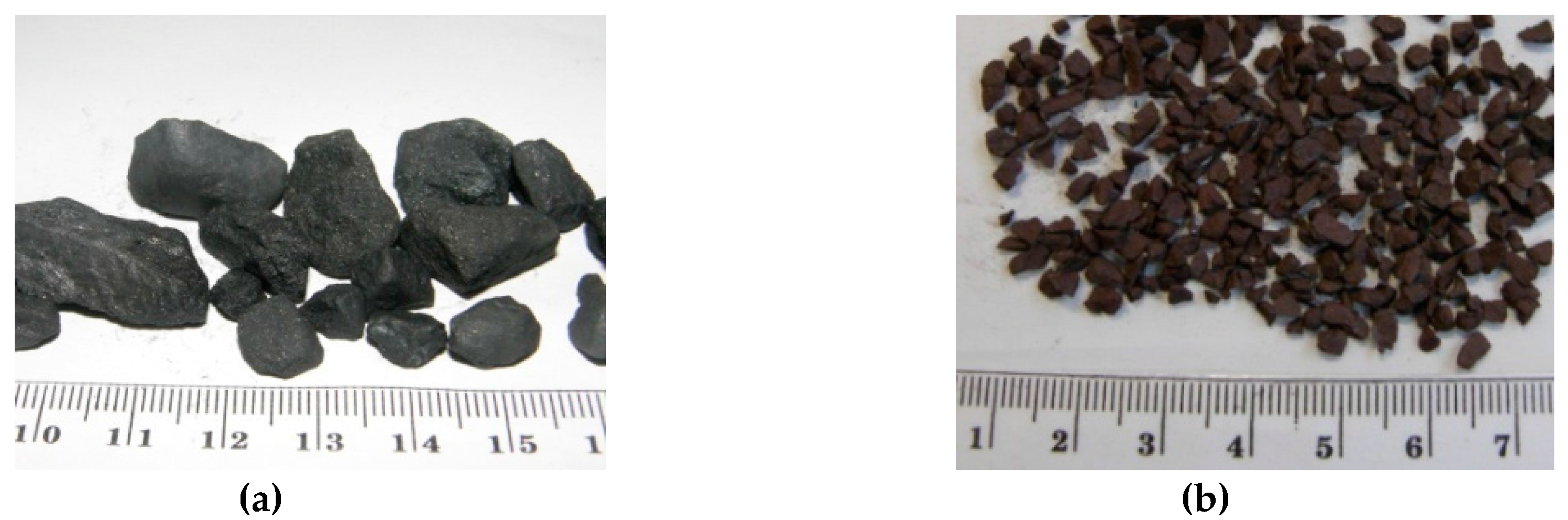
2.1. Materials
2.2. Methods
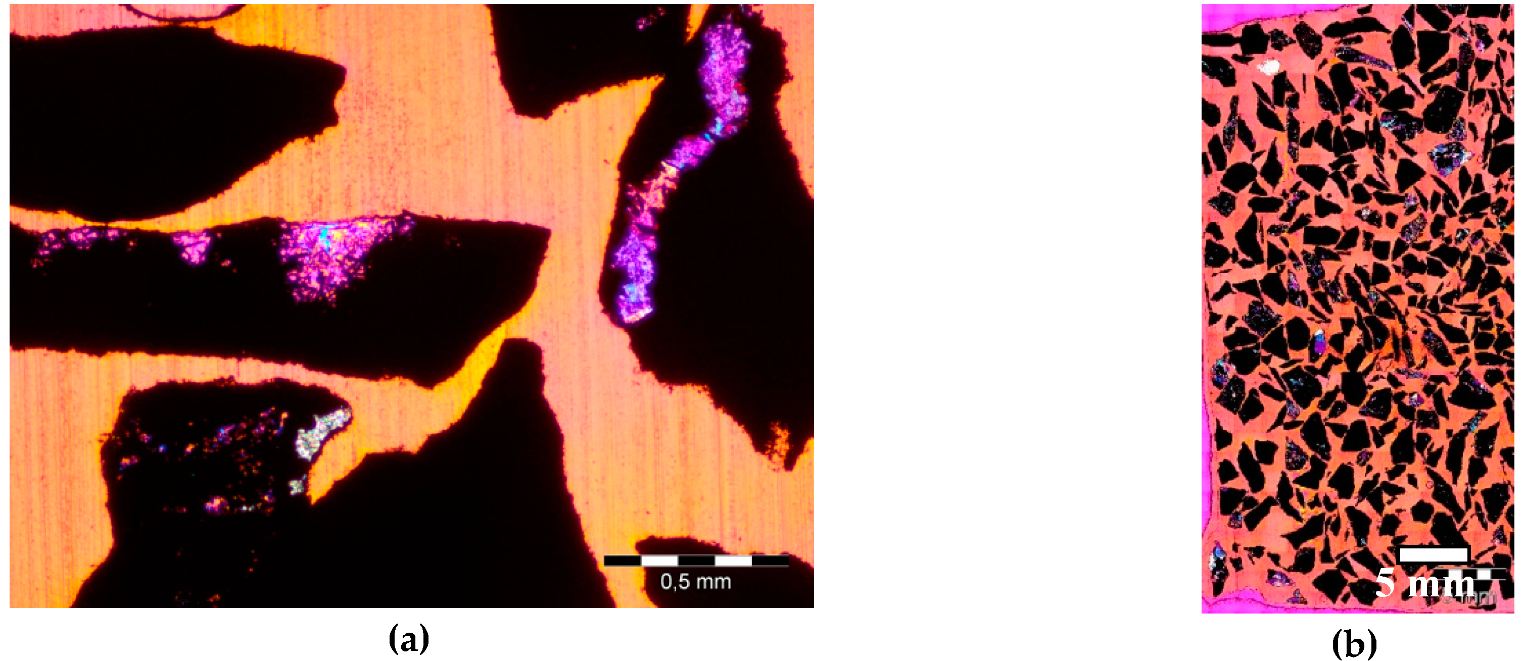
2.2.1. Thin Sections and Image Acquisition
2.2.2. Accelerated Expansion of Mortar-Bar
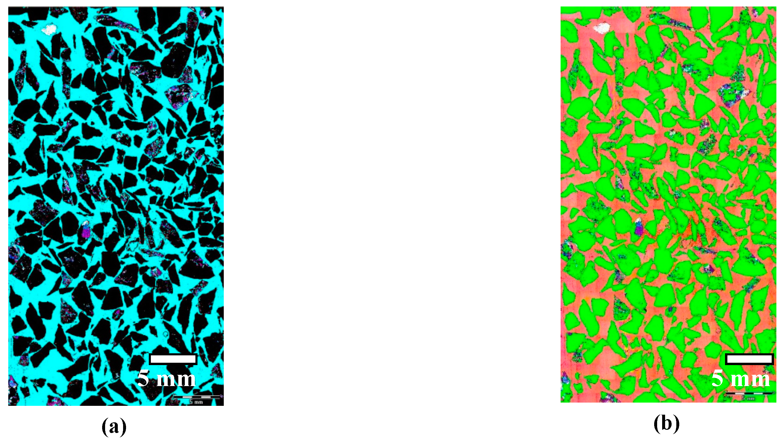
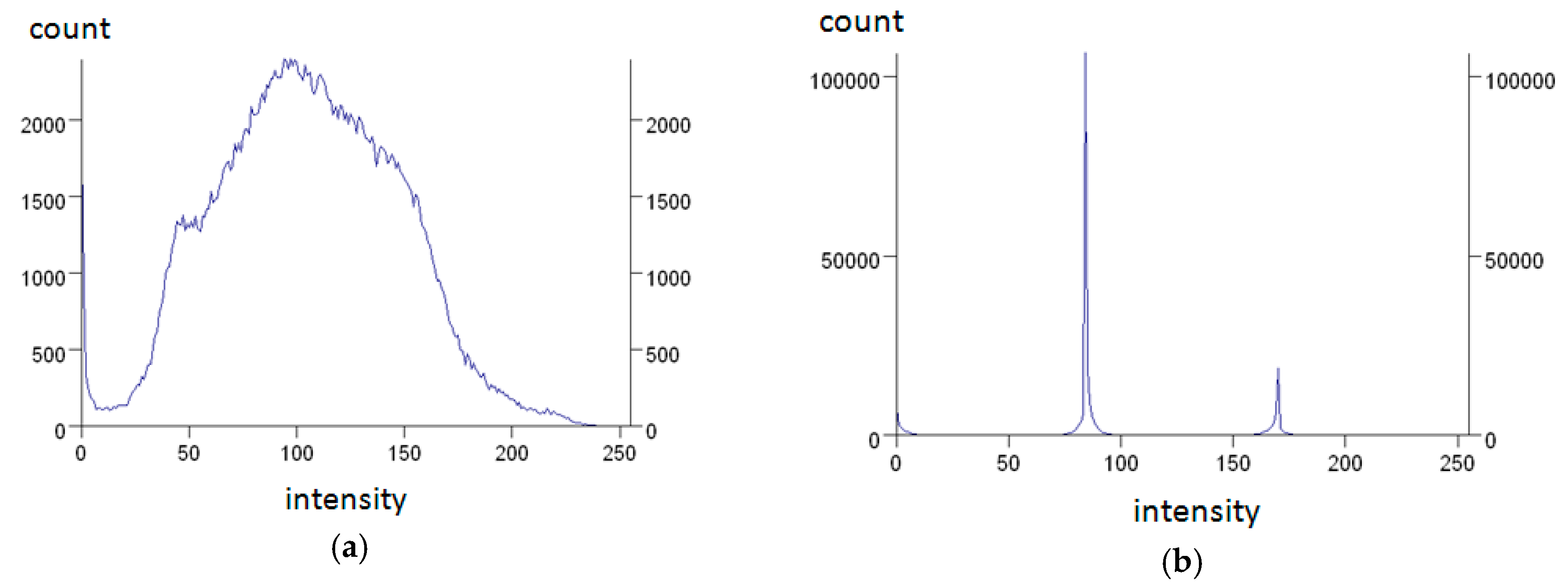
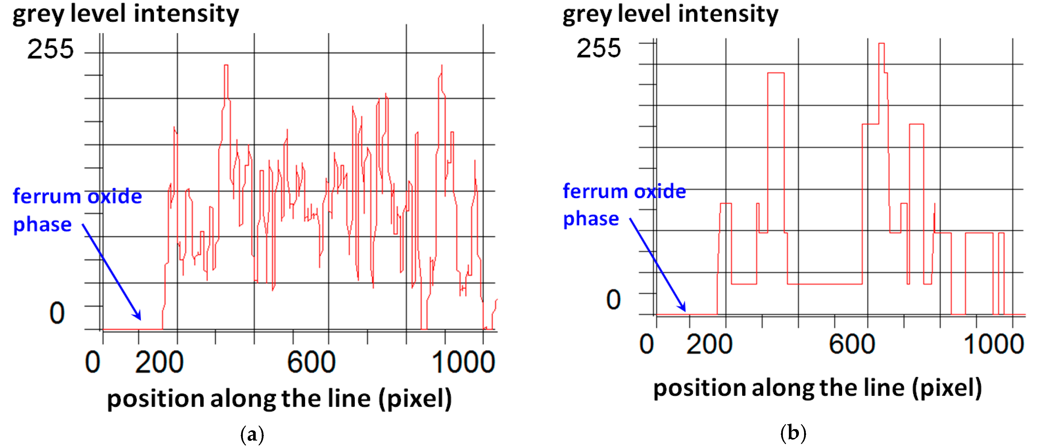
3. Image Analysis Procedure
4. Test Results and Discussion
4.1. Aggregate
4.2. Mortars
5. Conclusions
- 1.
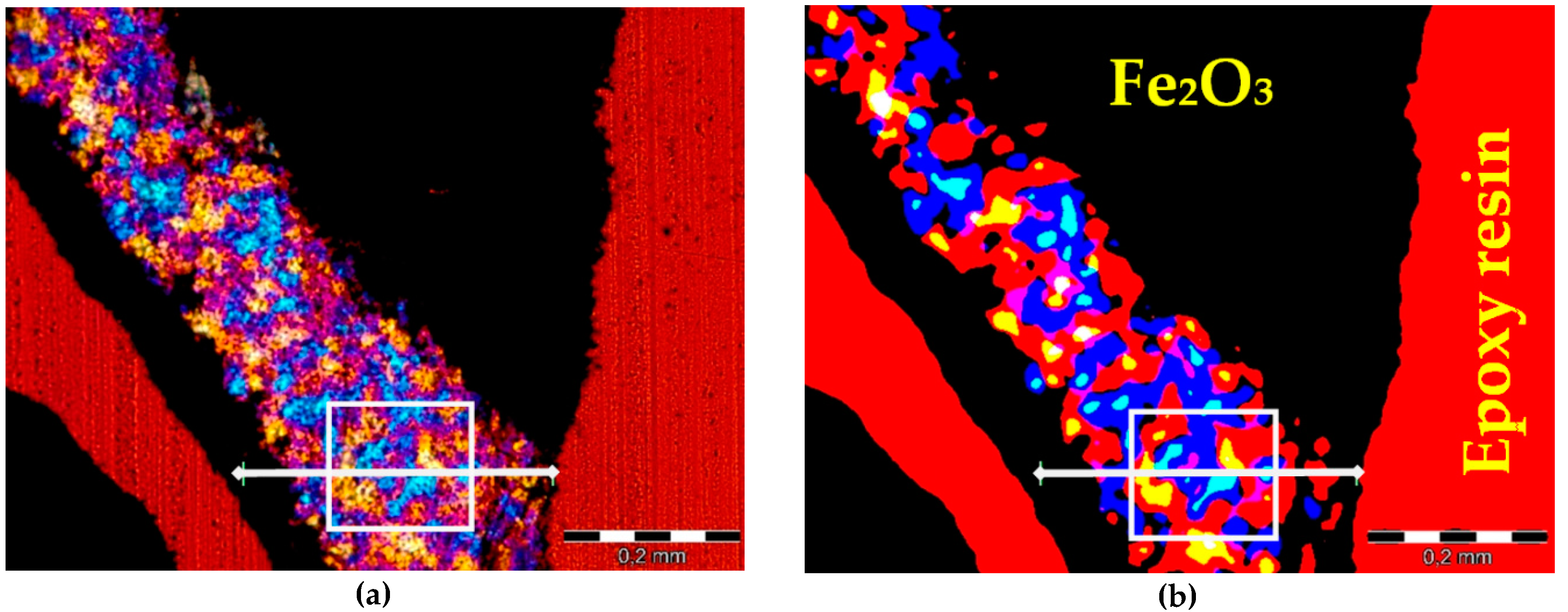
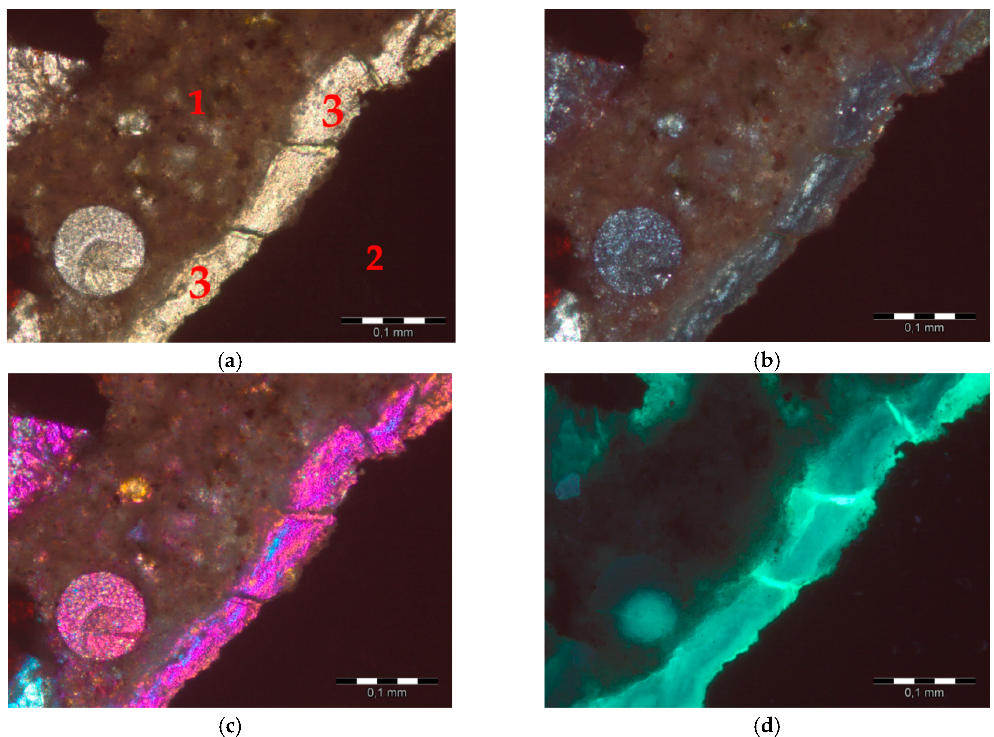
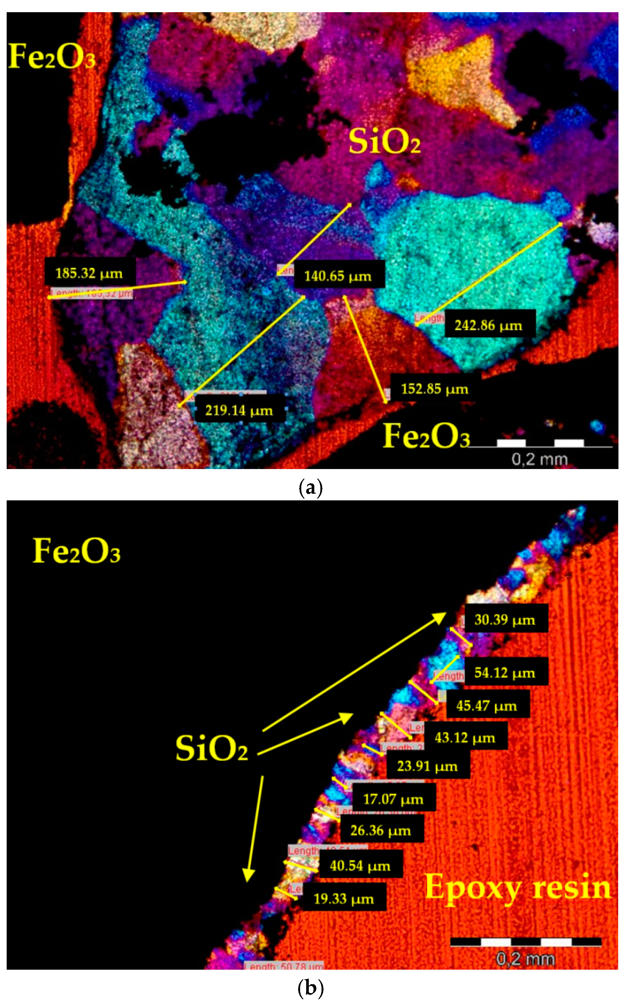
- An experimental method of quantitative evaluation of the content of quartz in heavyweight aggregates and its grain size distribution was developed. The method, based on microscopic image analysis of thin sections, studied in cross polarized light with λ plate, was effective in quartz characterization. Image processing consisting of identification of ferrum oxide and epoxy resin, and subsequent application of a set of filtering operations, resulted in an adequate image reduction allowing the grain size analysis.
- 2.
- The content of quartz in polymorphic hematite and magnetite aggregates, evaluated using the image analysis method, was quite close to results of XRF analysis on powder specimens, the absolute difference being 0.4% and 0.9% for magnetite and hematite aggregates, respectively.
- 3.
- The presence of the reactive quartz of the size range from 10 to 60 μm was revealed in tested heavy aggregates. The content of the reactive quartz grains was 2.67% and 0.13% for hematite and magnetite aggregates, respectively.
- 4.
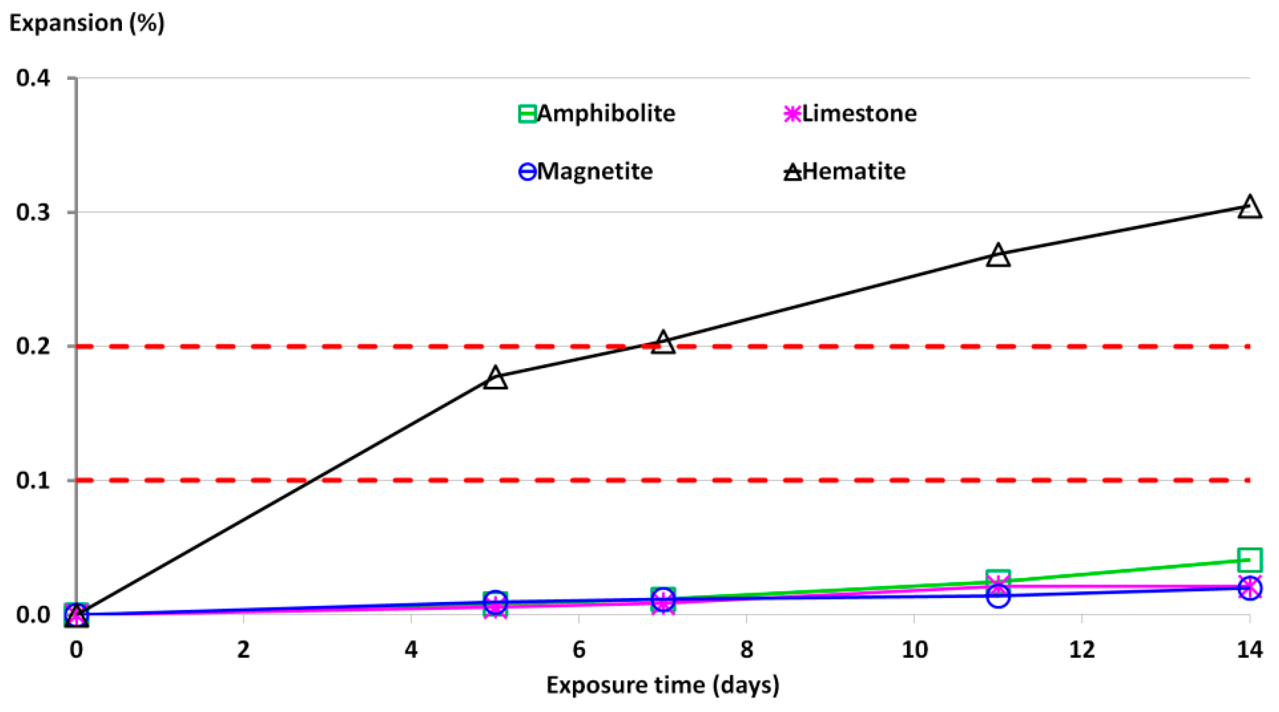
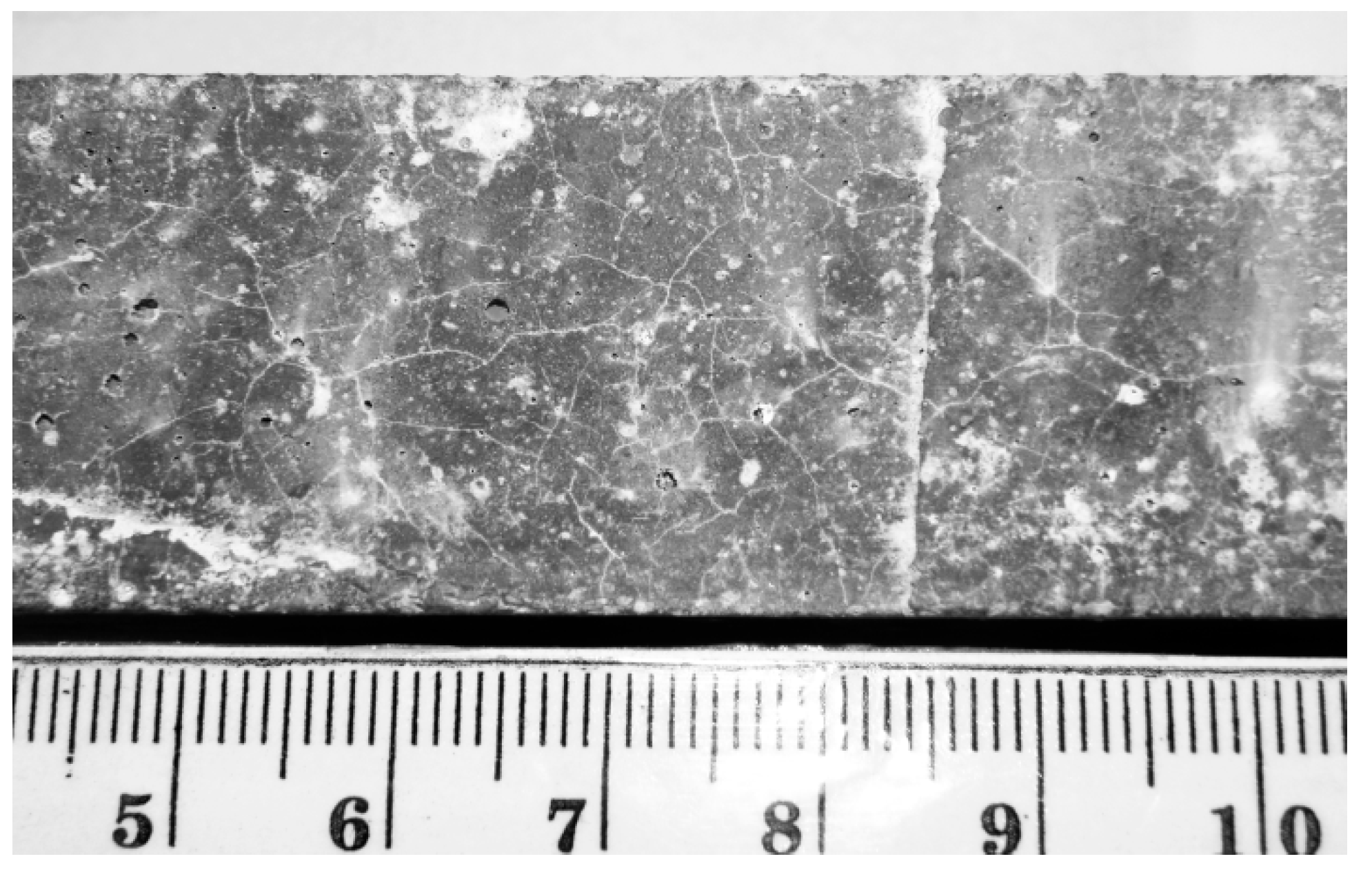
- Accelerated mortar bar tests revealed that hematite aggregates were prone to ASR, since the observed expansion of mortar specimens reached 0.30%–0.35% at 14 days of exposure to NaOH. For a higher content of reactive quartz grains, an increased expansion of mortar specimens was observed.
- 5.
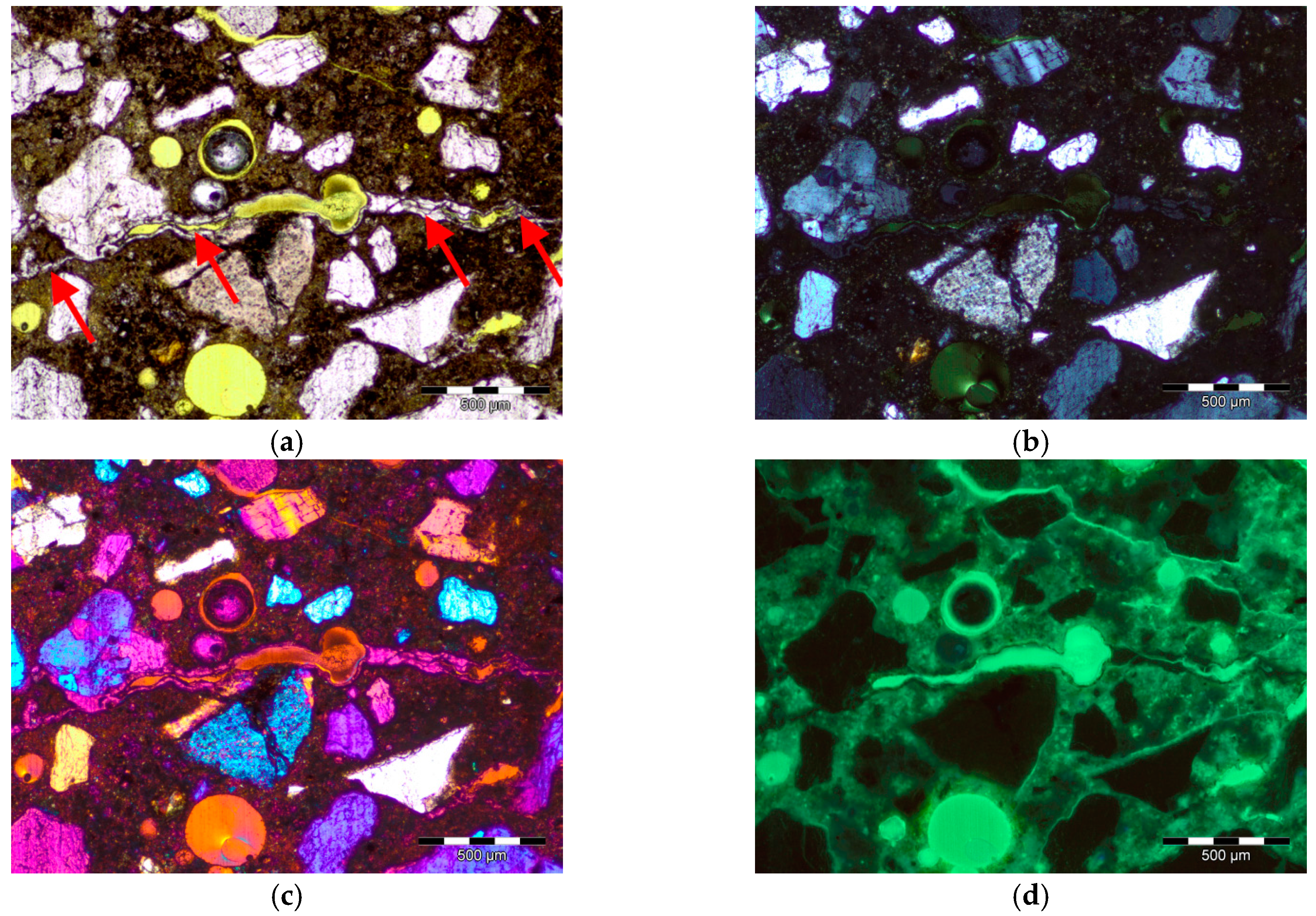
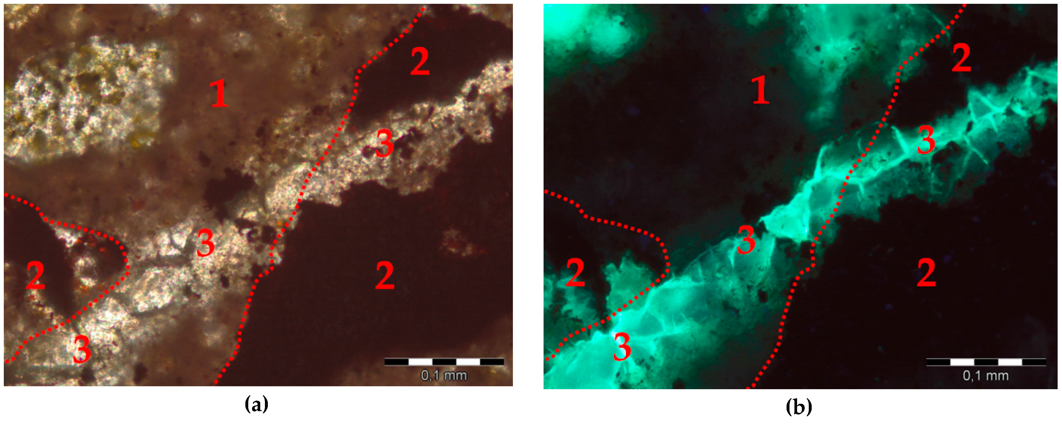
- The post-mortem analysis of thin sections prepared from mortars after ASTM C1260 test confirmed the presence of ASR gel, both in the matrix and in hematite aggregates.
Acknowledgments
Author Contributions
Conflicts of Interest
References
- Busby, J. Expanded Materials Degradation Assessment (EMDA); Volume 4: Aging of Concrete and Civil Structures; Oak Ridge National Laboratory: Oak Ridge, TN, USA, October 2014. [Google Scholar]
- Chénier, J.O.; Komljenovic, D.; Gocevski, V.; Picard, S.; Chrétien, G. An approach regarding aging management program for concrete containment structure at the gentilly-2 nuclear power plant. In Proceedings of 33rd Annual Conference of the Canadian Nuclear Society, TCU Place, Saskatoon, Saskatchewan, Canada, 10–13 June 2012; pp. 1–26.
- Saouma, V.E.; Hariri-Ardebili, M.A. A proposed aging management program for alkali silica reactions in a nuclear power plant. Nucl. Eng. Des. 2014, 277, 248–264. [Google Scholar] [CrossRef]
- Thomas, M.D.A.; Fournier, B.; Folliard, K.J. Alkali-Aggregate Reactivity (AAR) Facts Book; The Transtec Group: Austin, TX, USA, 2013. [Google Scholar]
- Balachandran, C.; Olek, J.; Rangaraju, P.; Diamond, S. Role of Potassium Acetate Deicer in Accelerating Alkali-Silica Reaction in Concrete Pavements. Transportat. Res. Rec. 2011, 2240, 70–79. [Google Scholar] [CrossRef]
- Hooton, R.D.; Rogers, C.; MacDonald, C.A.; Ramlochan, T. Twenty-year field evaluation of alkali-silica reaction mitigation. Aci. Mater. J. 2013, 110, 539–548. [Google Scholar]
- Justnes, H. Influence of SCMs on hydration and durability of blended cements: Chemical and physical principles. J. Chin. Ceram. Soc. 2015, 43, 1359–1371. [Google Scholar]
- Standard Guide for Reducing the Risk of Deleterious Alkali-Aggregate Reaction in Concrete; ASTM C1778–14; American Society for Testing of Materials: West Conshohocken, PA, USA, 2004.
- Rajabipour, F.; Giannini, E.; Dunant, C.; Ideker, J.H.; Thomas, M.D.A. Alkali–silica reaction: Current understanding of the reaction mechanisms and the knowledge gaps. Cement Concrete Res. 2015, 76, 130–146. [Google Scholar]
- Castro, N.; Wigum, B.J. Grain size analysis of quartz in potentially alkali-reactive aggregates for concrete: a comparison between image analysis and point-counting. In Proceedings of the 10th International Congress for Applied Mineralogy (ICAM), Trondheim, Norway, 1–5 August 2011; Broekmans, M.A.T.M., Ed.; Springer-Verlag: Berlin Heidelberg, Germany, 2012; pp. 103–110. [Google Scholar]
- Castro, N.; Wigum, B.J. Assessment of the potential alkali-reactivity of aggregates for concrete by image analysis petrography. Cement Concrete Res. 2012, 42, 1635–1644. [Google Scholar] [CrossRef]
- Fernandes, I.; dos Anjos Ribeiro, M.; Martins, H.; et al. Assessment of concrete aggregate for asr potential by petrography. In Engineering Geology for Society and Territory; Springer: New York, NY, USA, 2014. [Google Scholar]
- Jóźwiak-Niedźwiedzka, D.; Brandt, A.M.; Gibas, K.; Denis, P. The alkali-aggregate reaction hazard in the case of barite concretes. Cem. Wapno Beton 2014, 19, 234–242. [Google Scholar]
- Lukschova, Š.; Přikryl, R.; Pertold, Z. Petrographic identification of alkali–silica reactive aggregates in concrete from 20th century bridges. Constr. Build. Mater. 2009, 23, 734–741. [Google Scholar] [CrossRef]
- Stanton, T.E. Expansion of concrete through reaction between cement and aggregate. Proc. Am. Soc. Civ. Eng. 1940, 66, 1781–1811. [Google Scholar]
- Locati, F.; Marfil, S.; Baldo, E. Effect of ductile deformation of quartz-bearing rocks on the alkali-silica reaction. Eng. Geol. 2010, 116, 117–128. [Google Scholar] [CrossRef]
- Fernandes, I.; Broekmans, M.A.T.M.; Nixon, P.; Sims, I.; dos Anjos Ribeiro, M.; Noronha, F.; Wigum, B. Alkali–silica reactivity of some common rock types. A global petrographic atlas. Q. J. Eng. Geol. Hydroge. 2013, 46, 215–220. [Google Scholar] [CrossRef]
- Šachlová, Š.; Kuchařová, A.; Přikryl, R.; Fridrichová, M. Quantitative assessment of alkali silica reaction potential of quartz-rich aggregates: Comparison of chemical test and accelerated mortar bar test improved by SEM-PIA, Bulletin of Engineering Geology and the Environment. In B Eng. Geol. Environ.; 2015; Available online: http://link.springer.com/article/10.1007/s10064-015-0812-z (accessed on 26 October 2015).
- Standard Specification for Aggregates for Radiation-Shielding Concrete; ASTM C637–09; American Society for Testing of Materials: West Conshohocken, PA, USA, 2009.
- Nixon, P.J.; Sims, I. (Eds.) RILEM Recommendations for the prevention of damage by alkali-aggregate reactions in new concrete structures. In RILEM State-of-the-Art Report; Springer: Dordrecht, The Netherlands, 2016.
- Jóźwiak-Niedźwiedzka, D.; Glinicki, M.A.; Gibas, K.; et al. Expansion due to alkali-silica reaction of heavy aggregates used for nuclear shielding concrete. In Proceedings of International Symposium Brittle Matrix Composites, BMC-11, Warsaw. Brandt, France, 27–29 September 2015; pp. 353–360.
- Le Pape, Y.; Rosseel, T.M.; Remec, I.; et al. Perspectives on the role of concrete structures on the license renewal and long term operation of U.S. Nuclear Power Generation. In Proceedings of 2nd Conference on Technological Innovations in Nuclear Civil Engineering, West Conshohocken, PA, USA, 1–4 September 2004.
- Concrete degradation by alkali-silica reaction, NRC information notice 2011–20. United States Nuclear Regulatory Commission: Washington, 18 November 2011; p. 5. Available online: http://pbadupws.nrc.gov/docs/ML1122/ML112241029.pdf (accessed on 28 January 2016).
- Murazumi, Y.; Watanabe, Y.; Matsumoto, N.; et al. Study on the influence of Alkali-Silica reaction on structural behavior of reinforced concrete members. In Proceedings of 18th International Conference on Structural Mechanics in Reactor Technology, Beijing, China, 7–12 August 2005; pp. 2036–2042.
- Ichikawa, T.; Koizumi, H. Possibility of Radiation-induced degradation of concrete by alkali-silica reaction of aggregates. J. Nucl. Sci. Technol. 2002, 39, 880–884. [Google Scholar] [CrossRef]
- Morinaga, S. Preprint of East Asia Alkali-Aggregate Reaction Seminar; Tottori, Japan, 1997. [Google Scholar]
- Standard Guide for Petrographic Examination of Aggregates for Concrete; ASTM C 295–12; American Society for Testing of Materials: West Conshohocken, PA, USA, 2012.
- Wigum, B.J. Examination of microstructural features of Norwegian cataclastic rocks and their use for predicting alkali-reactivity in concrete. Eng. Geol. 1995, 40, 195–214. [Google Scholar] [CrossRef]
- Jóźwiak-Niedźwiedzka, D.; Gibas, K.; Brandt, A.M.; Glinicki, M.A.; Dąbrowski, M.; Denis, P. Mineral composition of heavy aggregates for nuclear shielding concrete in relation to alkali-silica reaction. Procedia Eng. 2015, 108, 162–169. [Google Scholar] [CrossRef]
- Standard Test Method for Potential Alkali Reactivity of Aggregates (Mortar-Bar Method); ASTM C 1260–14; American Society for Testing of Materials: West Conshohocken, PA, USA, 2014.
- Broekmans, M.A.T.M. Structural properties of quartz and their potential role for ASR. Mater. Charact. 2004, 53, 129–140. [Google Scholar] [CrossRef]
- Alaejos, P.; Lanza, V. Infuence of equivalent reactive quartz content on expansion due to alkali silica reaction. Cement. Concrete. Res. 2012, 42, 99–104. [Google Scholar] [CrossRef]
- Swamy, R.N. (Ed.) The Alkali-silica reaction in concrete; Van Nostrand Reinhold: New York, NY, USA, 1992.


| Main Mineral Constituents, % | Magnetite Aggregate | Hematite Aggregate | ||
|---|---|---|---|---|
| Supplier Data | Test Results | Supplier Data | Test Results | |
| SiO2 | 3.00 | 3.39 | 11.50 | 9.83 |
| Fe2O3 | 90.80 | 93.72 | 85.08 | 86.74 |
| Al2O3 | 0.40 | 0.51 | 0.90 | 0.68 |
| CaO | 2.50 | 1.72 | 0.05 | 0.02 |
| K2O | 0.20 | 0.10 | 0.40 | 0.27 |
| Na2O | 0.30 | 0.19 | 0.02 | 0.03 |
| Main Chemical Constituents | Cement 1 C1 | Cement 2 C2 | Cement 3 C3 |
|---|---|---|---|
| SiO2 | 22.20 | 19.03 | 21.48 |
| Al2O3 | 5.30 | 4.84 | 4.80 |
| Fe2O3 | 3.00 | 3.22 | 2.62 |
| CaO | 66.30 | 63.64 | 65.60 |
| MgO | 1.30 | 1.15 | 0.87 |
| SO3 | 0.60 | 2.97 | 2.84 |
| Na2O | 0.24 | 0.21 | 0.12 |
| K2O | 0.82 | 0.53 | 0.47 |
| Total Alkalis, Na2Oeq | 0.78 | 0.56 | 0.43 |
| Water-Soluble Alkalis | 0.54 | 0.48 | 0.37 |
| Loss of ignition (LOI) | 3.5 | 3.34 | 1.12 |
| Expansion, % | Aggregate Reactivity |
|---|---|
| <0.1 | Innocuous |
| 0.1–0.2 | Inconclusive |
| >0.2 | Potentially deleterious |
| Cristal Sizes | Magnetite Aggregate (%) | Hematite Aggregate (%) |
|---|---|---|
| total quartz grains | 3.60 | 11.62 |
| innocuous quartz: >130 μm | 3.24 | 7.41 |
| doubtful quartz: 60–130 μm | 0.22 | 1.46 |
| reactive quartz: 10–60 μm | 0.13 | 2.67 |
| highly reactive quartz: <10 μm | 0.01 | 0.08 |
| Heavyweight Aggregate | Highly Reactive Quartz <10 μm, % | Reactive Quartz 10–60 μm, % | Mortar bar Expansion after 14 days, % |
|---|---|---|---|
| Magnetite | 0.01 | 0.13 | 0.02 |
| Hematite | 0.08 | 2.67 | 0.31 |
© 2016 by the authors; licensee MDPI, Basel, Switzerland. This article is an open access article distributed under the terms and conditions of the Creative Commons by Attribution (CC-BY) license (http://creativecommons.org/licenses/by/4.0/).
Share and Cite
Jóźwiak-Niedźwiedzka, D.; Jaskulski, R.; Glinicki, M.A. Application of Image Analysis to Identify Quartz Grains in Heavy Aggregates Susceptible to ASR in Radiation Shielding Concrete. Materials 2016, 9, 224. https://doi.org/10.3390/ma9040224
Jóźwiak-Niedźwiedzka D, Jaskulski R, Glinicki MA. Application of Image Analysis to Identify Quartz Grains in Heavy Aggregates Susceptible to ASR in Radiation Shielding Concrete. Materials. 2016; 9(4):224. https://doi.org/10.3390/ma9040224
Chicago/Turabian StyleJóźwiak-Niedźwiedzka, Daria, Roman Jaskulski, and Michał A. Glinicki. 2016. "Application of Image Analysis to Identify Quartz Grains in Heavy Aggregates Susceptible to ASR in Radiation Shielding Concrete" Materials 9, no. 4: 224. https://doi.org/10.3390/ma9040224