3.1. Experimental Test Data
The special-shaped CFTs coupled with multiple cavities are often applied in specific super high-rise buildings; the related experimental test data are seldom available. Only data of tests conducted by the authors of this paper are documented and available for review. Therefore, this article only focuses to discuss the data of axial compressive test for the six special-shaped CFT columns with multiple cavities, as these were conducted by the authors, to study an equivalent uniaxial stress-strain relationship for a confined concrete. By considering the cross-sectional shape, the cavity construction, the concrete strength, the steel strength, and the reinforcement arrangement in cavities differ in each column, the equivalent uniaxial stress-strain relationship that worked out from the test results has good applicability.
3.1.1. Construction Details
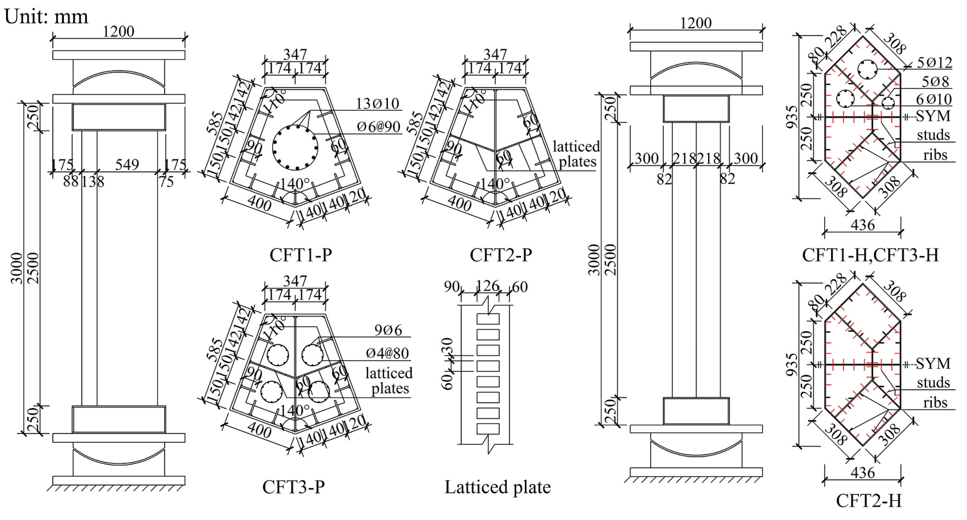
Six special-shaped CFT columns coupled with multiple cavities were designed in accordance with actual CFT columns in super high-rise buildings. The six columns were divided into two groups as follows: (1) the group P that includes three irregular pentagonal CFT columns coupled with multiple cavities, and (2) the group H that includes three irregular hexagonal CFT columns coupled with multiple cavities. The scales of group P columns and group H columns, respectively, are 1/5 and 1/12. The real prototype mega column of group P has a cross sectional area of 45 m2, whereas group H is approximately equal to 9 m2. All the specimens were designed by using the geometric similarity principle.
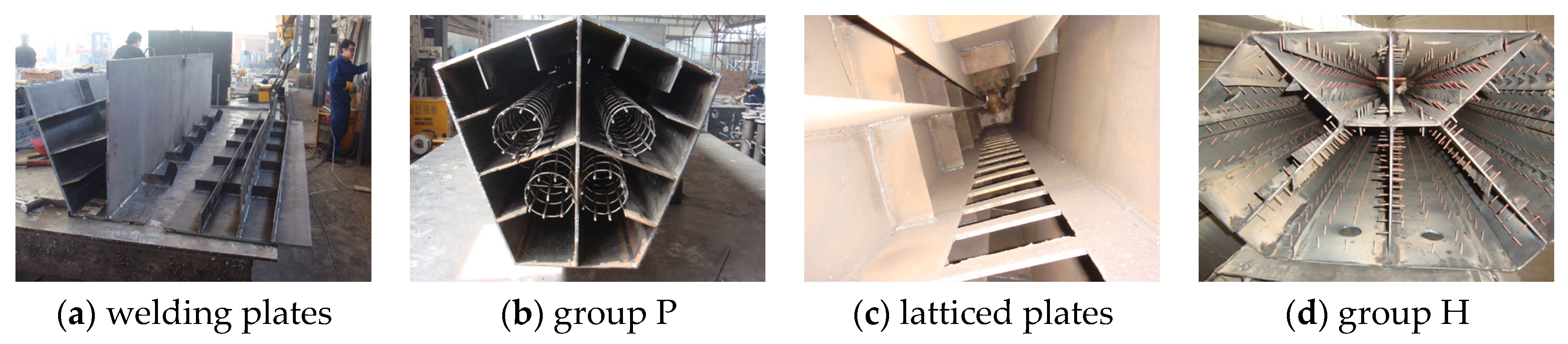
Group P columns were named CFT1-P, CFT2-P and CFT3-P, respectively. The cross-sectional geometric dimensions of external steel tubes that were welded by 12 mm steel plates are same. The vertical continuous stiffening ribs, whose cross sectional dimensions were 90 mm × 6 mm, were welded to an inside face of an external steel tube, whereas five story horizontal continuous stiffening ribs were welded at a vertical spacing of 500 mm. For the case of the columns CFT2-P and CFT3-P, the cross-section was divided into two cavities by using a 10 mm thick solid partition steel plate, and, thereafter, it was divided into four cavities by using two 6 mm thick symmetrical lattice partition steel plate on which rectangular holes were punched to make it easy for flow of concrete between the adjacent cavities. Group H specimens were named CFT1-H, CFT2-H, CFT3-H, respectively. The cross-sectional geometric dimensions of steel tubes, which were welded into a hexagon along with six cavities by using a 5 mm steel plate, were the same. The vertical continuous stiffening ribs along with a cross-section of 25 mm × 3 mm were welded to the inside face of an external steel tube and to the both faces of the partition steel plates. The studs along with a diameter of 4 mm, a length of 30 mm and a spacing 60 mm×60 mm were welded to the same place as the vertical continuous stiffening ribs. For the column specimens CFT1-P, CFT3-P, CFT1-H and CFT3-H, the longitudinal reinforcement is arranged into cavities by using a welded spacer bar to improve the shrinkage of mass concrete and the heat of hydration issues as well as to constrain the inner concrete. The main parameters and the running parameters of the six specimens have been figured out, as these have been shown in
Table 1. The construction details have also been shown in
Figure 2, whereas the construction photos have been shown in
Figure 3.
Table 1.
Main parameters of the specimens.
Table 1.
Main parameters of the specimens.
| Group | Name | Shape | Quantity of Cavities | Cross-Sectional Area | Concrete Strength | Equivalent Steel Strength | Steel Plate Ratio | Steel-Bars Ratio |
|---|
| A (m2) | fcu,m (Mpa) | fc,m (Mpa) | (Mpa) | ρ1 (%) | ρ2 (%) | ρ3 (%) |
|---|
| P | CFT1-P | Irregular pentagon | 1 | 0.354 | 51.1 | 38.8 | 378.5 | 7.81 | 1.68 | 0.29 |
| CFT2-P | 4 | 385.8 | 7.81 | 3.60 | 0 |
| CFT3-P | 4 | 385.7 | 7.81 | 3.60 | 0.29 |
| H | CFT1-H | Irregular hexagon | 6 | 0.313 | 30.7 | 23.3 | 300.5 | 3.42 | 2.60 | 0.82 |
| CFT2-H | 6 | 42.0 | 31.9 | 295.0 | 3.42 | 2.60 | 0 |
| CFT3-H | 6 | 42.0 | 31.9 | 300.5 | 3.42 | 2.60 | 0.82 |
Figure 2.
Column construction details.
Figure 2.
Column construction details.
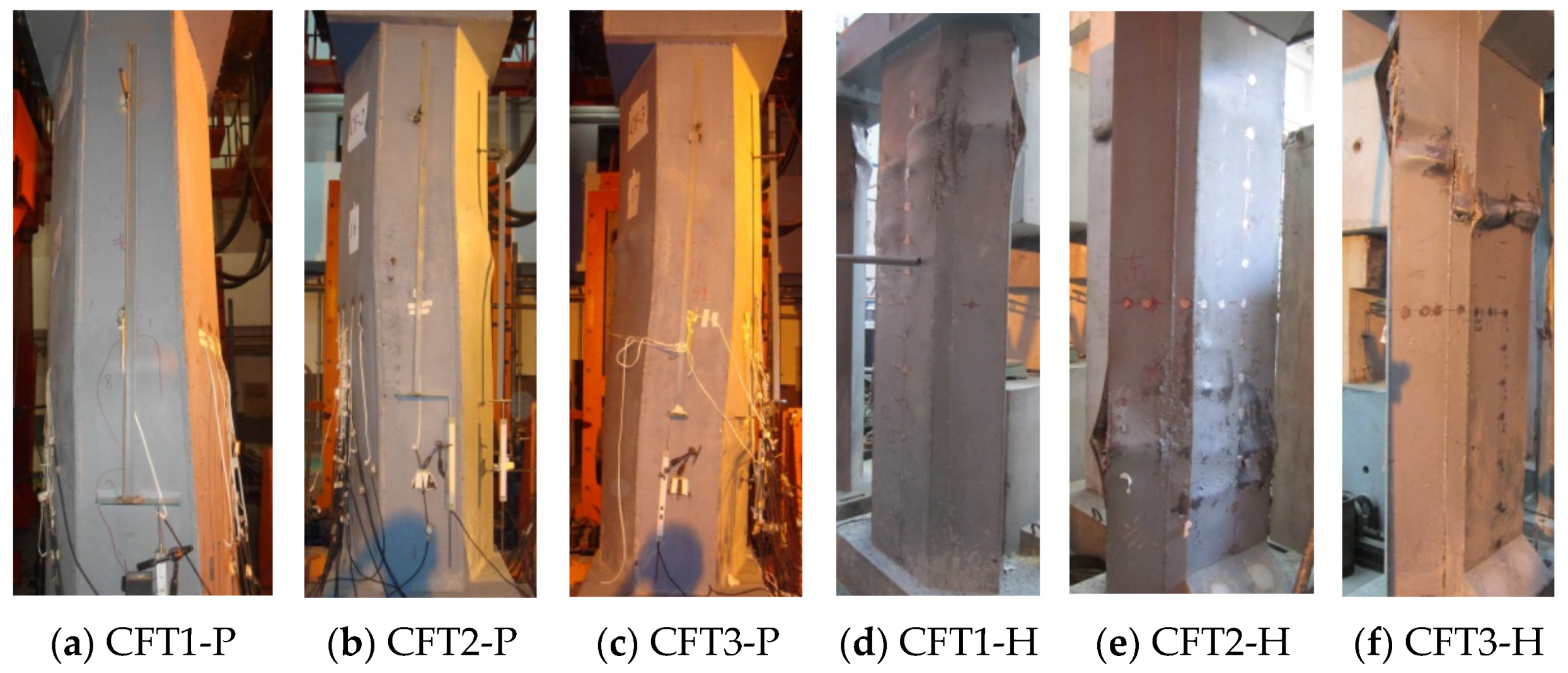
Figure 3.
Column construction pictures.
Figure 3.
Column construction pictures.
3.1.2. Material Properties
The concrete strength has been shown in
Table 1. The tested yield strength, the ultimate strength, the tensile elongation, the elasticity modulus of reinforcement and the steel plates have been shown in
Table 2.
Table 2.
Mechanical properties of reinforcement and steel plates.
Table 2.
Mechanical properties of reinforcement and steel plates.
| Group | Type | Location | fy (MPa) | fu (MPa) | ρ (%) | Es (MPa) |
|---|
| P | 6 mm steel plate | Vertical and horizontal stiffening ribs, lattice partition steel plate | 416 | 528 | 27.5 | 2.10 × 10⁵ |
| 10 mm steel plate | Solid partition steel plate | 409 | 498 | 27.6 | 2.12 × 10⁵ |
| 12 mm steel plate | External steel tube | 373 | 525 | 27.4 | 2.06 × 10⁵ |
| ø6 reinforcement | Longitudinal reinforcement | 382 | 582 | 31.3 | 2.07 × 10⁵ |
| ø10 reinforcement | Longitudinal reinforcement | 310 | 473 | 36.7 | 2.05 × 10⁵ |
| H | 5 mm steel plate | Steel tube | 296 | 428 | 28.9 | 2.06 × 10⁵ |
| ø8 reinforcement | Longitudinal reinforcement | 334 | 445 | 24.5 | 2.05 × 10⁵ |
| ø10 reinforcement | Longitudinal reinforcement | 363 | 446 | 26.3 | 2.07 × 10⁵ |
| ø12 reinforcement | Longitudinal reinforcement | 326 | 423 | 27.1 | 2.04 × 10⁵ |
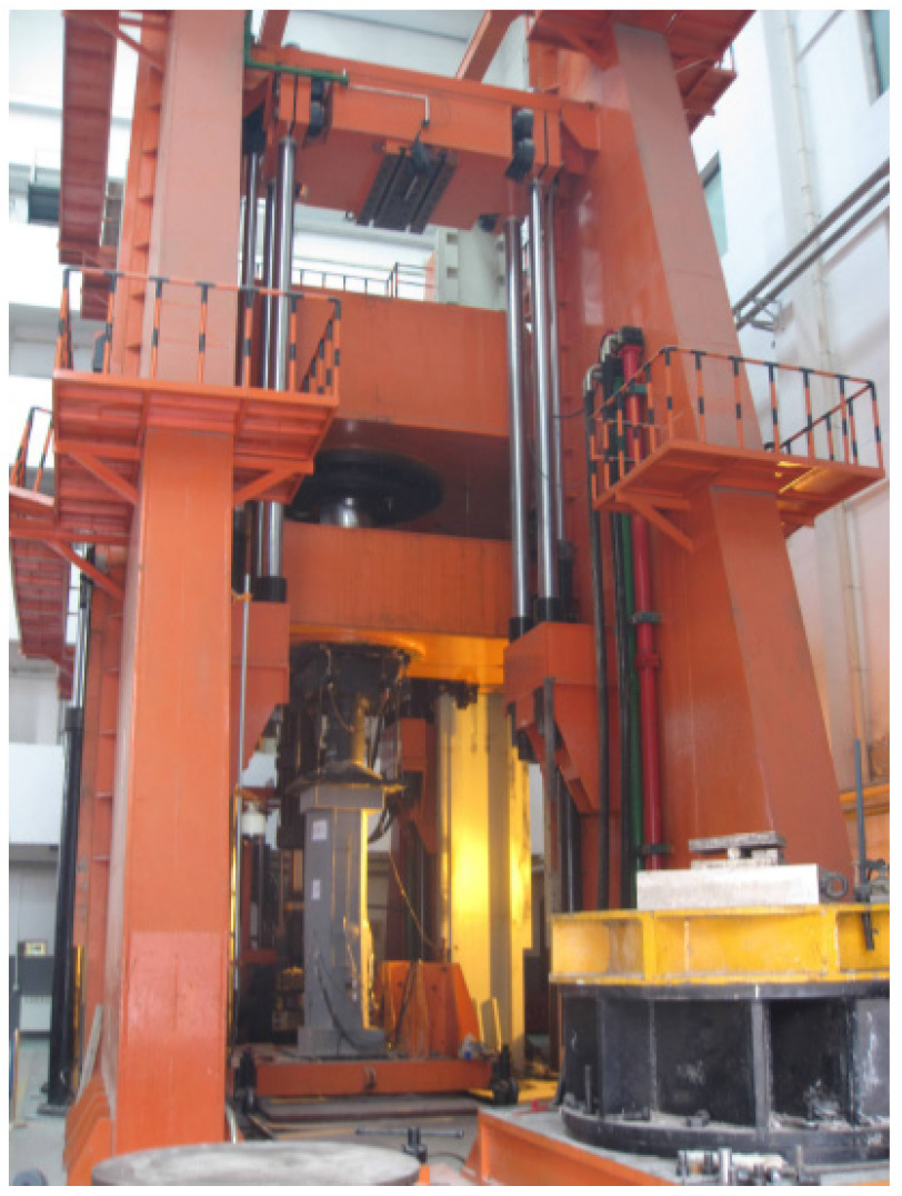
3.1.3. Experimental Set-Up
A 40,000 kN universal testing machine was used to conduct the axial compressive tests. The axial load is applied at the centroid of the cross-section. The coordinate of the centroid is calculated by formulas and , where is the strength of concrete part or steel part, and is the area of concrete part or steel part. On the upper and the lower end of the loading device, the spherical hinges have been arranged. During the testing, a cyclically uniaxial load was applied to the specimens to study the residual deformation each time the unloading was finished. To prevent the overturn of the specimens, the device was unloaded to 2000 kN. During the initial stage (i.e., the elastic stage), the specimens were loaded at the intervals of one-sixth an estimated ultimate load. After evident yield appeared on the load-displacement curves, the loading process principle turned out to be controlled by displacement.
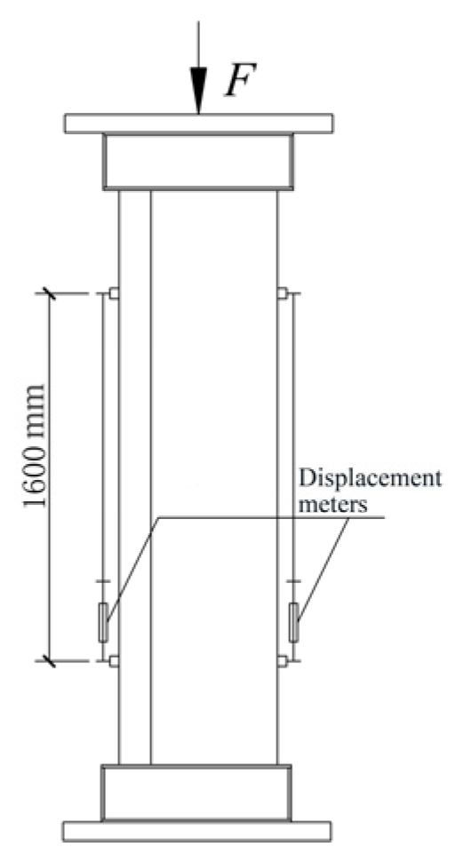
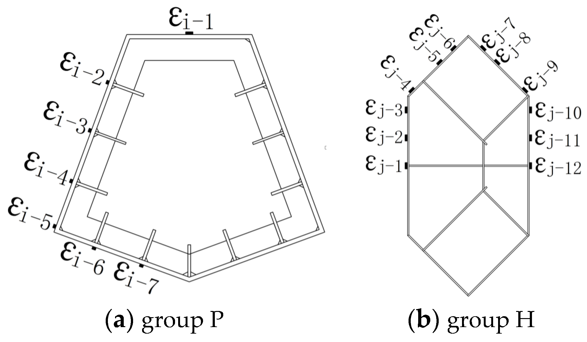
The two displacement meters, which were used to measure the vertical displacement, were arranged in the central part of the specimens, where the deformation was uniform. The gauge length of the displacement meters is 1600 mm. The strain gauges to measure longitudinal deformation were also placed on the exterior of steel plates of central steel tubes in the vertical direction. The real-time values of the load, the displacement and the strain were gathered by using a data gathering system; the buckling of external steel tube and crack of welding seams were recorded manually. The test scene photo has been shown in
Figure 4. The arrangement of displacement meters has been shown in
Figure 5; the distribution of the strain gauges has also been shown in
Figure 6.
Figure 5.
Displacement meters arrangement.
Figure 5.
Displacement meters arrangement.
Figure 6.
The arrangement of strain gauges.
Figure 6.
The arrangement of strain gauges.
3.1.4. Test Phenomenon
All the specimens went through a similar failure process,
i.e., wrinkling of oil painted skin, buckling of steel plates, cracking of welding seams, breaking of concrete,
etc. The final failure patterns have been shown in
Figure 7.
There are few differences between the two groups of specimens. The wrinkling of oil painted skin in group P specimens is horizontal cracks, while that in group H specimens is 45-degree staggered cracks. It shows that the vertical strain develops faster than the hoop strain in group P specimens, while the vertical strain develops close to the hoop strain in group H specimens. The buckling regions of group P specimens are few and concentrate in only two to three regions, but each buckling region is large; by contrast, the buckling regions of group H specimens are numerous and scattered, but each local buckling region is small and protruding. There are great differences between the two groups of specimens. The reason is that the steel ratio of group P specimens is higher than that of group H specimens by 58.63% to 85.05%. The cross sectional moment of inertia of group P specimens in the two main directions is close to each other, whereas it is not close to each other in the case of group H specimens. Owing to an arrangement of strong vertical and horizontal stiffening ribs, the stability of external steel tubes of group P specimens is better and the confinement effect to infill concrete is stronger.
Figure 7.
Failure patterns of specimens.
Figure 7.
Failure patterns of specimens.
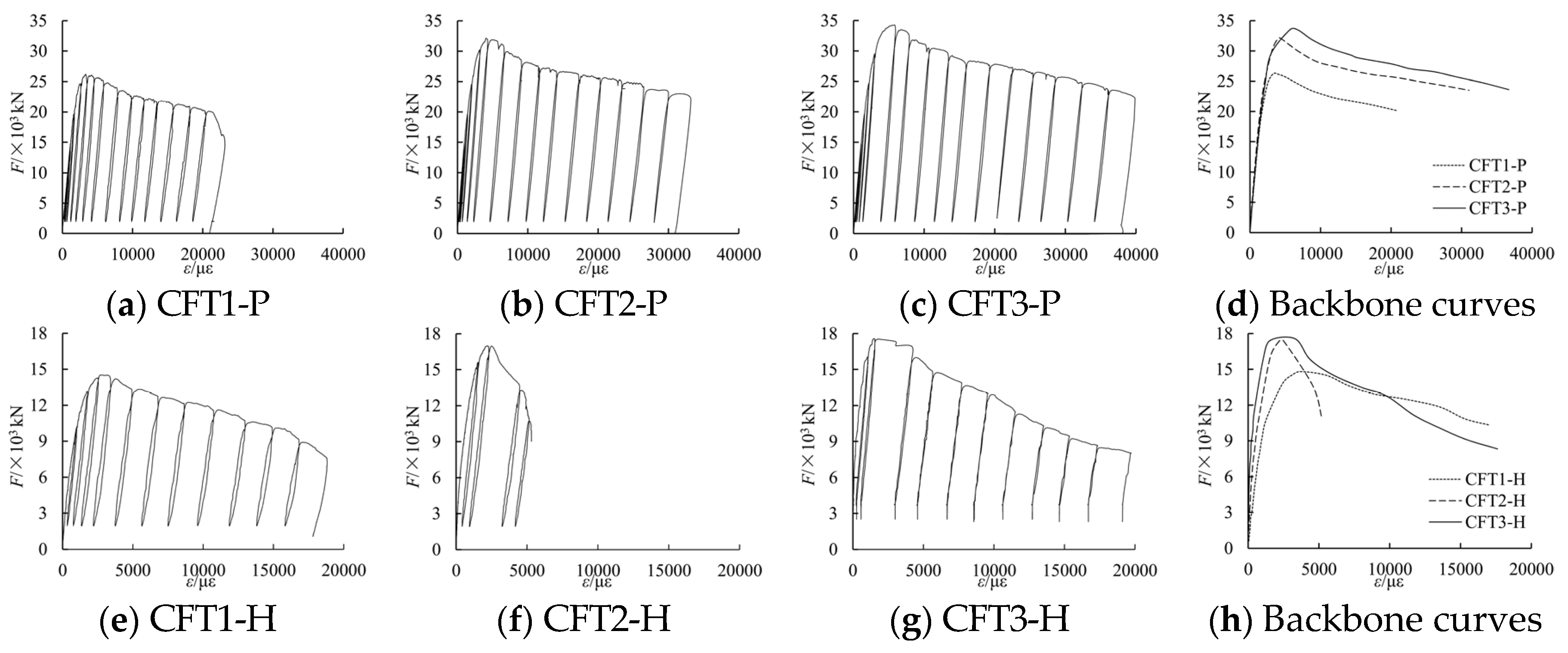
3.1.5. Load F-Average Strain ε Curves
Under a cyclically uniaxial load, the tested load
F-average strain ε curves and the related backbone curves of the six columns have been shown in
Figure 8. In
Figure 8,
F is the applied axial load during the testing process, whereas ε is the average strain that is switched from the related displacement in the 1600 mm gauge length of the middle of columns. The tested characteristic points have been shown in
Table 3. In
Table 3,
Fut is the tested peak load, whereas ε
ut is the tested strain related to
Fut;
Fu0 is the aggregate value bearing capacity
s of concrete and the steel part.
Figure 8.
Tested F-ε curves and backbone curves of specimens.
Figure 8.
Tested F-ε curves and backbone curves of specimens.
Table 3.
Peak results of specimens.
Table 3.
Peak results of specimens.
| Columns | CFT1-P | CFT2-P | CFT3-P | CFT1-H | CFT2-H | CFT3-H |
|---|
| Fut/kN | 26233 | 32119 | 33496 | 14800 | 17400 | 17557 |
| εut/με | 3316 | 4049 | 5650 | 3144 | 2495 | 2800 |
| Fu0 | 24370 | 26268 | 26612 | 12636 | 14343 | 15138 |
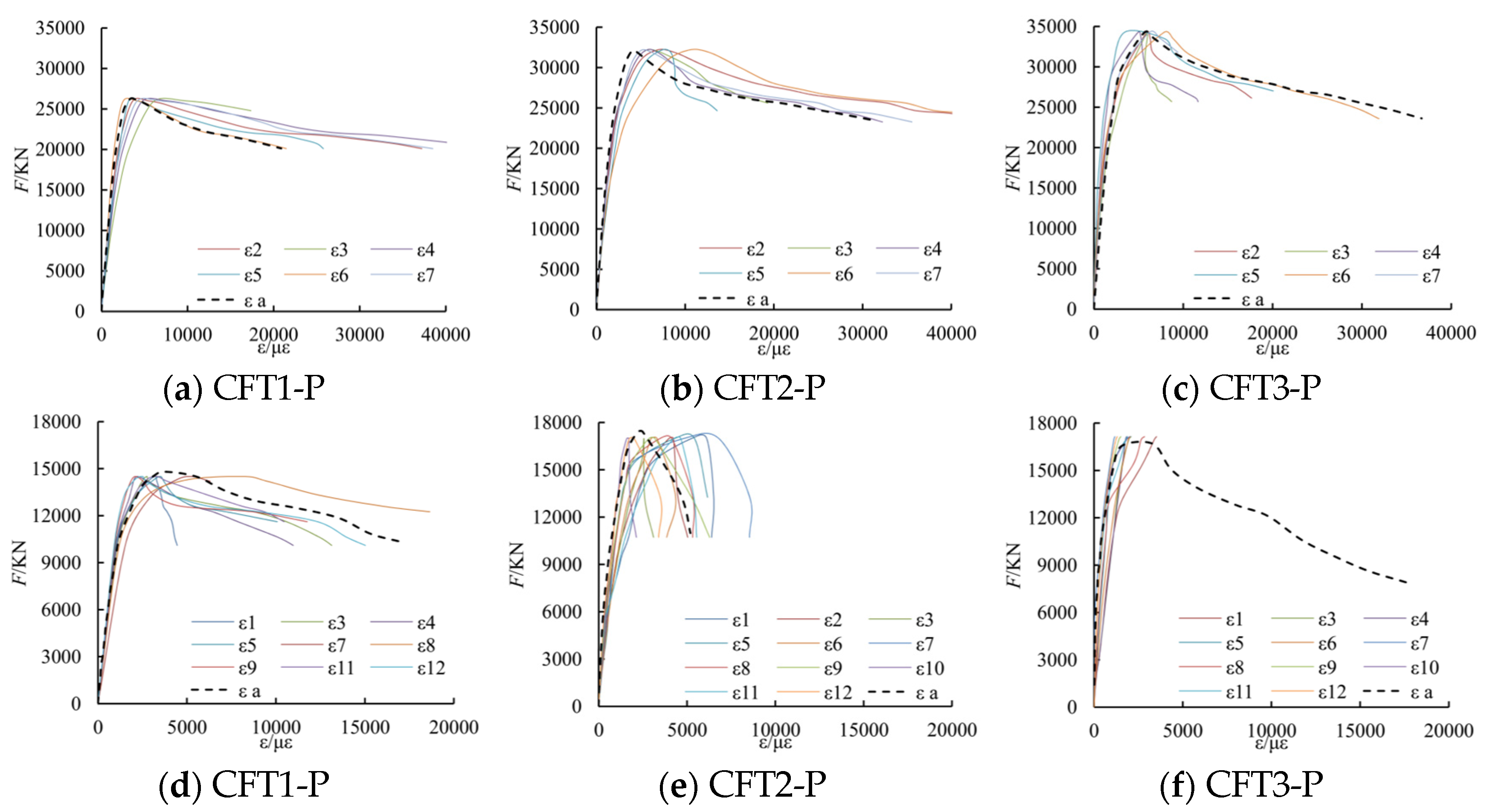
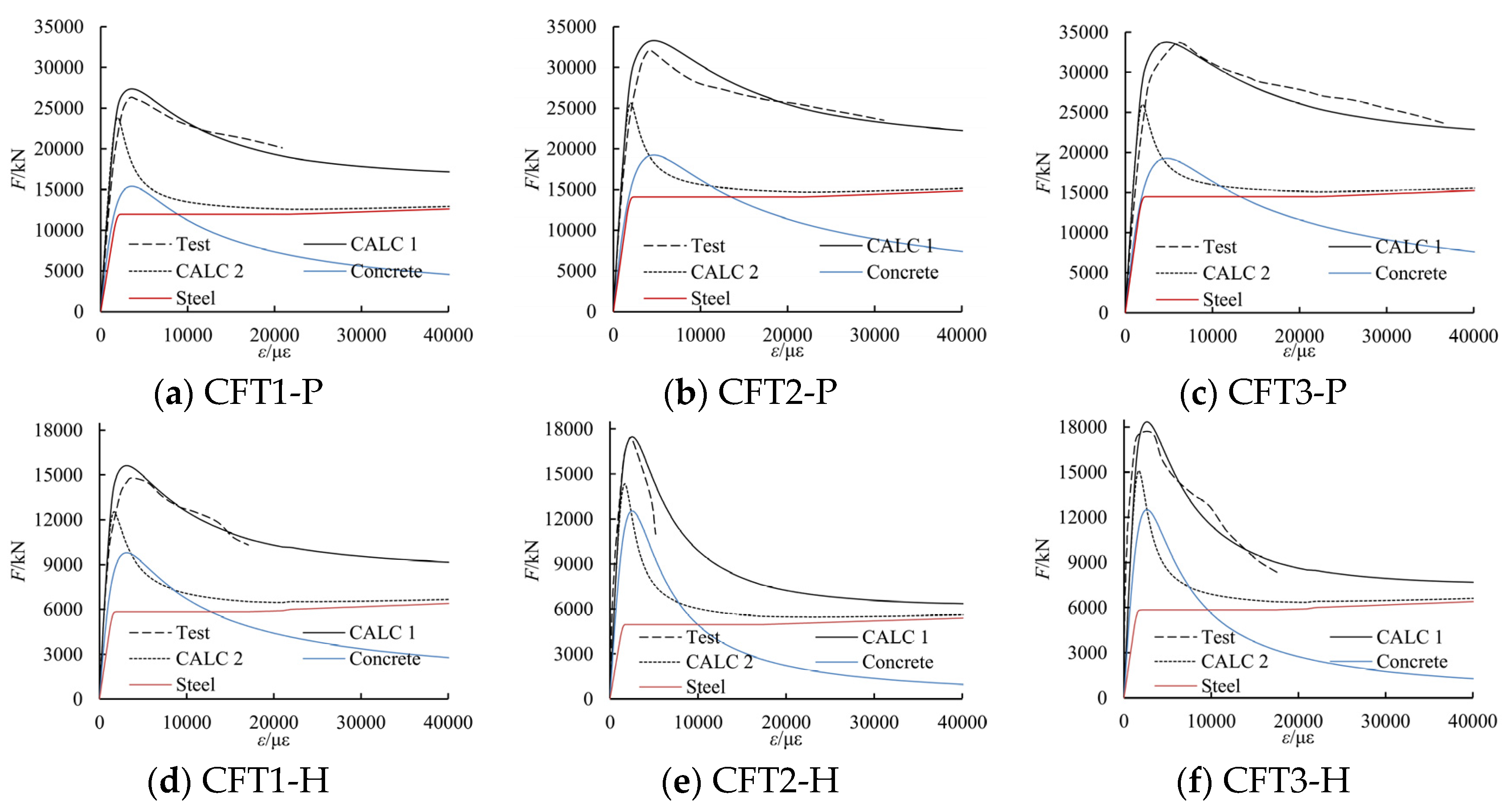
3.1.6. Backbone Curves of Load F-Measured Strain εi
Parts of the tested backbone curves of load
F-measured strain ε
i curves are shown in
Figure 9. In the figure, ε
a is the tested average strain switched from the related displacement.
From the figure, it can be known that the change law of the measured stain by strain gauges is similar to the average stain switched from the related displacement. Moreover, when the longitudinal deformation of the columns reaches a larger value, local buckling of the steel plate may occur, so that the strain measured by strain gauges may not be accurate any more. Thus, in this paper, in order to simply calculations and reduce errors, the average strain switched from the related displacement is applied to study the relationship of the concrete confined by special-shaped steel tube coupled with multiple cavities.
Figure 9.
Backbone curves of F-εi.
Figure 9.
Backbone curves of F-εi.
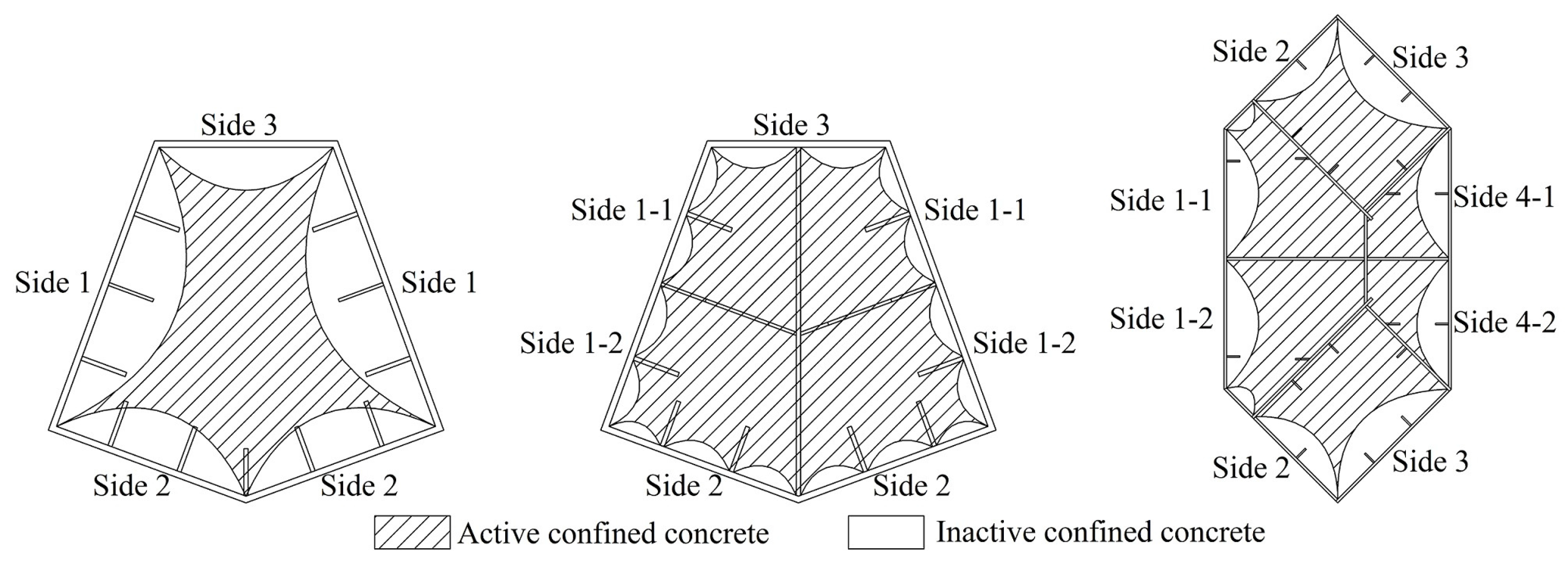
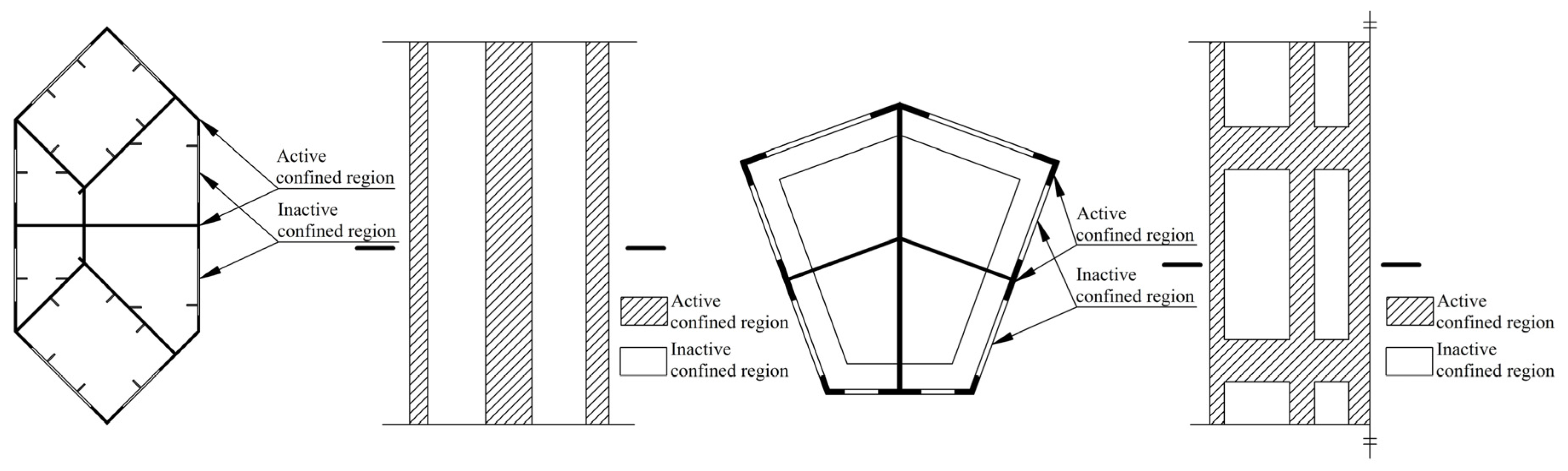
3.2. Determination of the Effective Confinement Coefficient ke
The confinement action of core concrete that is confined by a special-shaped CFT coupled with multiple cavities is different from one that is confined by normal reinforcement. The external steel tube has strong confinement action at the corners and the locations that were provided with partition steel plates, longitudinal stiffening ribs or transversal stiffening ribs. The confinement action is relatively weak at the central part of the external steel tube plate that may exist either between the two adjacent longitudinal stiffening ribs or between the adjacent longitudinal stiffening rib and the partition steel plate. Therefore, the cross-sectional boundary in transversal direction between the active confined region and the inactive confined region is assumed to be a parabola, the same as occurs in lateral cross-section due to similar confinement features between the two adjacent transverse stiffening ribs.
The cavity construction and the arrangement of stiffening ribs in two group columns differ from each other. If the arranged stiffening ribs are weak, the confinement action of the steel tube to the core concrete is relatively weak. In that case, the concrete near to the stiffening ribs cannot be divided into the active confined region. Keeping this in view, specific criteria has been proposed to evaluate whether the stiffening ribs are able to offer sufficient confinement ability or not. Firstly, the division of active and inactive confined regions is based on the straight sides of the external steel tube. In case the boundary parabola intersects all the longitudinal stiffening ribs whose width to thickness ratios are relatively small, sufficient confinement ability can preliminary be verified. Secondly, if the boundary parabola only intersects parts of the longitudinal stiffening ribs, a parameter S describing the contribution of stiffening ribs of the cavity side on the whole cavity is additionally used to verify the confinement ability. Similarly, the confinement ability of transversal stiffening ribs has been assured by S. The expression of parameter S can be written as follows:
, where Aj is the cross-sectional area of stiffening ribs on one cavity side, bj is the length of cavity side, cj is the perimeter of the cavity, and Aaj is the cross-section area of the cavity.
The issue of confinement ability of stiffening ribs is very complex and needs extensive research. Additionally, the samples of experimental column are limited, so the validity of stiffening ribs can be determined on a qualitative basis only. The estimated results have been shown in
Table 4. The division of active and inactive confined concrete has been shown in
Figure 10.
Table 4.
The validity determination of stiffening ribs.
Table 4.
The validity determination of stiffening ribs.
| Columns | Evaluating Parameters | Side Number | CFT1-P | CFT2-P | CFT3-P | Side Number | CFT1-H | CFT2-H | CFT3-H |
|---|
| Longitudinal stiffening ribs | b/t | - | 15 | 15 | 15 | - | 8.3 | 8.3 | 8.3 |
| S/% | 1-1 | 1.958 | 3.192 | 3.192 | 1-1 (1-2) | 0.850 | 0.850 | 0.850 |
| 1-2 | 2.530 | 2.530 | 2 | 0.787 | 0.787 | 0.787 |
| 2 | 1.948 | 3.809 | 3.809 | 3 | 0.526 | 0.526 | 0.526 |
| 3 | - | - | - | 4-1 (4-2) | 0.542 | 0.542 | 0.542 |
| Validity | - | Inactive | Active | Active | - | Inactive | Inactive | Inactive |
| Transverse stiffening ribs | b/t | - | 15 | 15 | 15 | - | - | - | - |
| S/% | 1-1 | 0.435 | 3.629 | 3.629 | - | - | - | - |
| 1-2 | 2.128 | 2.128 |
| 2 | 0.649 | 1.686 | 1.686 |
| 3 | 0.743 | 1.270 | 1.270 |
| Validity | - | Inactive | Active | Active | - | - | - | - |
Figure 10.
The active confined concrete and inactive confined concrete.
Figure 10.
The active confined concrete and inactive confined concrete.
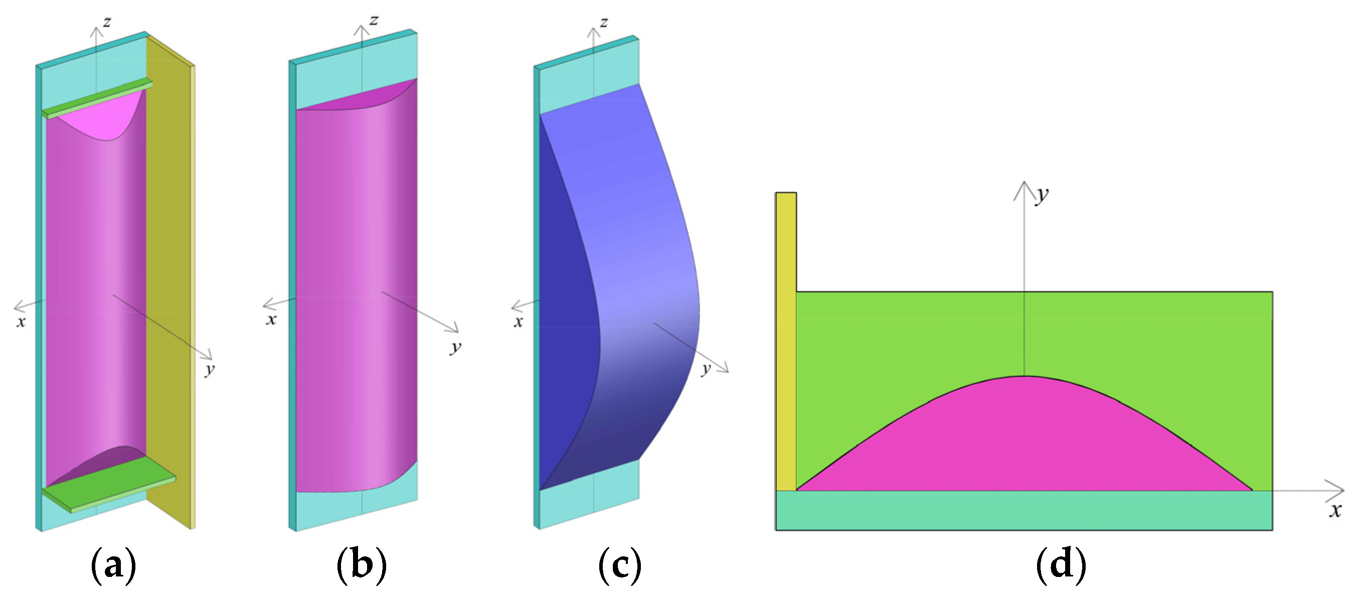
To determine the extent to which concrete is confined actively, a local coordinate system o-
xyz has been defined, as it has been shown in
Figure 11. The
x axis is parallel to the straight side; the
y axis is perpendicular to the straight side; and the
z axis is in the longitudinal direction of the column. The distance either between the adjacent effective longitudinal stiffening ribs or between the adjacent effective longitudinal stiffening rib and the partition steel plate is
b. The distance between the adjacent effective transversal stiffening ribs is regarded as
H. If the points of intersection between the parabola and steel plate side are (−
b/2, 0) and (
b/2, 0) and the included angle between the tangent line of the parabola and steel plate side at the points of intersection is θ, the transversal boundary between the active confined concrete and the inactive confined region can be expressed by using the relation:
. Analogously, the lateral boundary can be expressed by using the relation:
.
Figure 11.
Schematic diagram of 3D boundary of inactive and active cofined concrete. (a) Isolated body; (b) Transverse boundary; (c) Lateral boundary; (d) Plane graph.
Figure 11.
Schematic diagram of 3D boundary of inactive and active cofined concrete. (a) Isolated body; (b) Transverse boundary; (c) Lateral boundary; (d) Plane graph.
The maximum value of f(x) and g(z) may not be equal to each other. When H is greater than that of b, g(z)max is greater than that of f(x)max, and the transversal boundary differs from the lateral boundary. It shows that the confinement action in transversal cross-section is stronger than that of the lateral cross-section. The transversal confinement action is sufficient; therefore, the transverse boundary can be regarded as a primary boundary.
It is logical to know that when , then g(z) = f(x)max = . Therefore, the 3D boundary of active and inactive confined concrete can be expressed as follows:
When or , the included angle between the tangent line of the parabola f(x) and the axis at the intersection points changes along with the z value. The f(x)max can be determined by using the relation g(z). The parabola f(x) intersects xz plane at points (−b/2, 0, z) and (b/2, 0, z); therefore, the transversal boundary can be modified to be included as: .
When , the transversal boundary cannot be modified and the expression is considered as: .
As a result, the final 3D boundary can be written as:
To simplify the estimation, a constant value of θ = 45° is applied [
26]. The volume of the inactive confined concrete can be calculated by using Equation (7). In the estimation process, the distance between the two adjacent active transversal stiffening ribs can be regarded as an effective length
H. If there are no active transversal stiffening ribs, the whole length of column can be regarded as an effective length.
The coefficient of active confinement can be calculated by using Equation (8). In Equation (8),
Vc presents the whole volume of the concrete in the columns within the effective length
H.
when
H is smaller than that of
b,
g(
z)
max is smaller than that of
f(
x)
max. The confinement action in transversal cross-section is weaker than that of the lateral cross-section. In addition, the estimation method of
ke is similar to that when
H is greater than
b. Moreover, in general design of special-shaped CFT coupled with multiple cavities,
h <
b is unusual.
3.3. Determination of Hooping Stress fsr and Longitudinal Stress fa
For a general design, the issue of local buckling for steel plates is usually considered, and the steel tube is often found in a relatively balanced state. Hence, united parameter is applied to describe the issue of local buckling. By neglecting the radial stress, the steel plate of tube is assumed to be in a plane stress state and it accords with von Mises yield criterion. Ge [
27] shows that the parameter of width to thickness
R is a major factor that influences the damage of in-filled concrete. When
R > 0.85, the local buckling may appear before the applied load reaches the ultimate bearing capacity; when
R ≤ 0.85, the issue of local buckling may be neglected, but the longitudinal stress of steel tube can not reach the yielding stress owing to the opposite sign of stress fields.
The width to thickness parameter of each side in the isolated body has been shown in Equation (9), where
t is the thickness of steel plate and,
ν is the Poisson ratio.
The equivalent width to thickness parameter of the special-shaped steel tube with multiple cavities has been shown in Equation (10).
When
R > 0.85, the yielding strength of steel tube plate, due to local buckling, can be assessed by using Equation (11).
During estimation,
ν = 0.283 [
13], even though the stiffening ribs in columns CFT1-H–CFT3-H are inactive in the division of active and inactive region of confined concrete, they are active in considering local buckling of the steel tube plate. The estimated results have been shown in
Table 5, and the issue of local buckling for all the columns in this article does not need to be considered.
By neglecting the issue of local buckling, Sakino
et al. [
28] have suggested that the hooping stress
fsr and the longitudinal stress
fa can be assumed as 0.19
fy and −0.89
fy respectively, whereas Architectural Institute of Japan (AIJ) [
29] standard suggested that the hooping stress
fsr and the longitudinal stress
fa can be assumed as 0.21
fy and −0.89
fy, respectively. By considering the non-uniformity of the special-shaped CFT coupled with multiple cavities in this paper, the smaller values of
fsr = 0.19
fy was applied in the estimation process.
To simplify the estimation, the stress path of steel tube plate was simplified into a straight line, as has been shown in
Figure 12.
Table 5.
Estimated results of related parameters of confined concrete.
Table 5.
Estimated results of related parameters of confined concrete.
| Columns | CFT1-P | CFT2-P | CFT3-P | CFT1-H | CFT2-H | CFT3-H |
|---|
| ke | 0.461 (0.498) | 0.856 | 0.856 (0.498) | 0.699 | 0.702 | 0.699 |
| 0.346 | 0.255 | 0.255 | 0.465 | 0.465 | 0.465 |
| fl | 3.563 (0.648) | 4.692 | 4.692 (0.648) | 2.473 | 2.473 | 2.473 |
| fl | 1.641 (0.323) | 4.017 | 4.015 (0.323) | 1.729 | 1.735 | 1.729 |
| ξ1 | 0.8309 | 0.8476 | 0.8503 | 0.4638 | 0.3361 | 0.3391 |
| ξ2 | 0.0255 | 0 | 0.0316 | 0.1290 | 0 | 0.0943 |
| ξ3 | 0.1991 | 0.8992 | 0.9021 | 0.7075 | 0.5126 | 0.5172 |
| ξ | 1.0555 | 1.7468 | 1.7840 | 1.3003 | 0.8487 | 0.9506 |
| η | 3.800 | 2.796 | 2.855 | 2.353 | 1.528 | 1.720 |
| fc0 | 38.84 | 38.84 | 38.84 | 23.32 | 31.90 | 31.90 |
| εc0 | 1772 | 1772 | 1772 | 1531 | 1671 | 1671 |
| Ec | 32831 | 32831 | 32831 | 26269 | 30753 | 30753 |
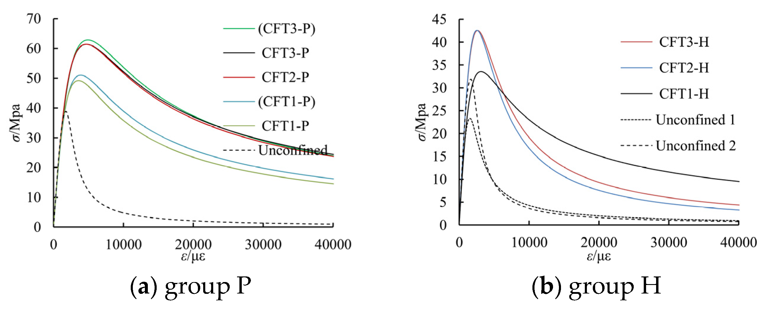
| fcc | 49.12 (51.01) | 61.41 | 61.40 (62.87) | 33.55 | 42.57 | 42.53 |
| εcc | 3565 (3881) | 4654 | 4709 (4901) | 3111 | 2523 | 2629 |
| r | 1.725 (1.718) | 1.673 | 1.659 (1.705) | 1.696 | 2.213 | 2.109 |
| Fut/kN | 27312 | 33343 | 33760 | 15350 | 17470 | 18343 |
| Fut/Fut | 1.041 | 1.038 | 1.008 | 1.037 | 1.004 | 1.045 |
| εcc/εut | 1.075 | 1.149 | 0.834 | 0.990 | 1.011 | 0.939 |
Figure 12.
Curve of hooping and longitudinal stresses of steel tube.
Figure 12.
Curve of hooping and longitudinal stresses of steel tube.
3.4. Determination of Equivalent Tensile Force Fb of Partition Steel Plate at Peak Point
The stress status of a solid partition steel plate is similar to that of steel tube. The radial stress can be neglected, as it is relatively small in comparison with longitudinal and hooping stresses. It is assumed that the partition steel plate can be in a plane stress status and accords with von Mises yield criterion. Both sides of the steel plate are constrained by concrete. Therefore, the issue of local buckling can be avoided. The estimation method of longitudinal and hooping stresses can be used to refer to the steel tube plate when R < 0.85. In addition, the stress path can be simplified into a straight line.
The stress status of latticed partition steel plate is very complex. If the radical stress is neglected, the solid part of lattice partition steel plate can be assumed to be in a plane stress status, whereas the latticed part can be assumed to be in a one-dimensional stress status. When the applied load reaches to the ultimate bearing capacity, the equivalent tensile force of latticed partition steel plate can be estimated by Equations (12)–(14), where
Ab1 is the area of solid part,
Ab2 is the area of latticed part, and ε
b2 is the strain of latticed part that is corresponded to peak load.
The deformation compatibility condition can be met by assuming that there is no slippage between the lattice partition steel plate and the concrete. The equivalent tensile strain of the lattice partition steel plate can be taken as .
Han
et al. [
14] proposed the expression of the Poisson ratio of a core concrete at peak that was point based on axial compressive experimental research on plain concrete and CFT stud columns, as has been shown in Equation (15).
Estimation results show that the longitudinal solid plate part of the lattice partition steel plate is not able to provide enough transversal tensile stress. Therefore, the equivalent tensile force of the latticed partition steel plate can be assessed by Fb = Fb1.
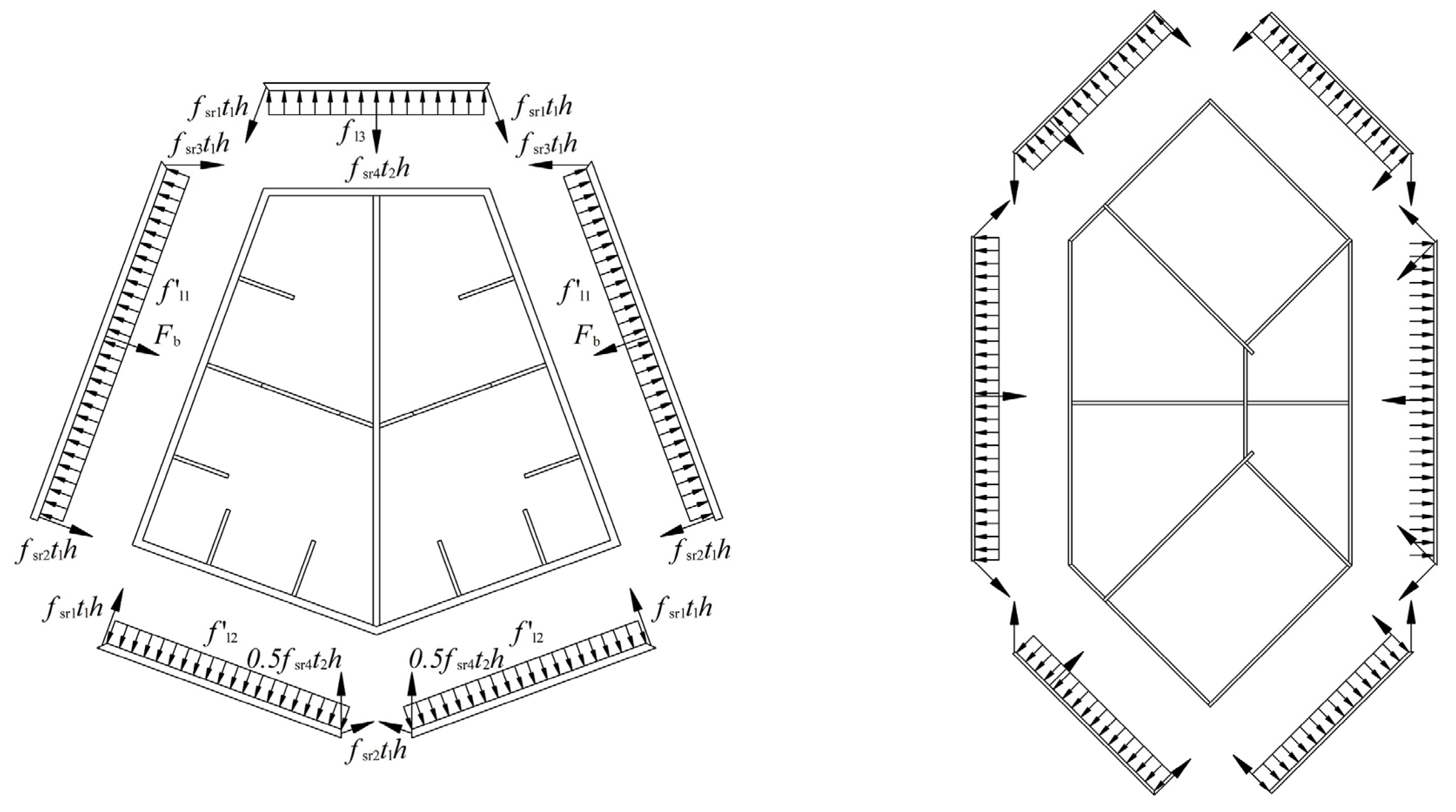
3.5. Determination of Equivalent Lateral Confining Stress of Concrete fl
The confinement action of a special-shaped steel tube coupled with multiple cavities is not uniform at the corners and at the center of the straight sides. To make it convenient to estimate, the confining stress of a special-shaped steel tube coupled with multiple cavities is equivalent to uniformly distribute and an active confinement coefficient ke is multiplied to reflect the influence of non-uniformity. During the calculation, the external steel tube plate of each cavity is taken as an isolated body. An equivalent average confining stress of all the external steel tube in each cavity can be gained by using the equilibrium condition.
The diagrams of isolated bodies of the two group columns are shown in
Figure 13. Equations (16)–(20) of group P are given, for instance.
Figure 13.
The diagrams of the isolated bodies of the specimens.
Figure 13.
The diagrams of the isolated bodies of the specimens.
For the columns CFT1-P, CFT3-P, CFT1-H and CFT3-H, the reinforcement is arranged in the cavities. The concrete rounded by reinforcement is confined by both reinforcements and special-shaped steel tube coupled with multiple cavities. Han [
14] shows that the stress of concrete near center is higher than that near straight sides for normal steel tube confined concrete. Thus, the confinement action of the concrete rounded by reinforcement in this paper is stronger than the average confinement action. To reflect this feature, a sum of the steel tube confining stress and the reinforcement confining stress, which are estimated by Mander’s methods, are applied as equivalent confining stress. The multiple confinement action is limited for the column CFT1-H and CFT3-H owing to the reason that no hooping reinforcement has been arranged. The reinforcement confining stress can be assessed by Equation (21) [
22], where ρ
s is ratio of the volume of transversal confining steel to the volume of confined concrete core,
fyh is the yield strength of the transversal reinforcement,
s is the clear vertical spacing between spiral or hoop bars,
ds is the diameter of spiral between the bar centers, and ρ
cc is the ratio of area of longitudinal reinforcement to area of core of section.
3.6. Determination of Modified Factor of Strain at Maximum Concrete Stress η
The modified factor of strain at maximum concrete stress η is a constant value in Mander’s confined concrete model. In fact, the value of η varies along with the confinement action. In a special-shaped CFT coupled with multiple cavities, the value of η is related to cross-section shape, stiffening ribs, cavity construction, concrete strength and steel strength. After comprehensive analysis, it can be observed that the influence of cross-sectional shape, stiffening ribs and cavity construction have been reflected by the parameter
ke. Thus, the remaining factors can be reflected by material confinement coefficient ξ. The parameter ξ is divided into three parts as follows: (1) the first part ξ
1 is the coefficient of material confinement for the external steel tube; (2) the second part ξ
2 is the coefficient of material confinement for reinforcement; and (3) the third part ξ
3 is the coefficient of material confinement for partition steel plate and stiffening ribs. The parameter ξ
3 can be determined by using the material strength, the area, and the share times of cavities. For instance, if a part or whole partition steel plate is shared by two cavities, during the estimation of ξ
3, the area of the part or whole partition steel plate can be multiplied by two; if the longitudinal stiffening ribs are verified as effective, the area would be multiplied by two; except for the above situation, the area would be multiplied by one during the estimation of ξ. The equation of ξ are as follows:
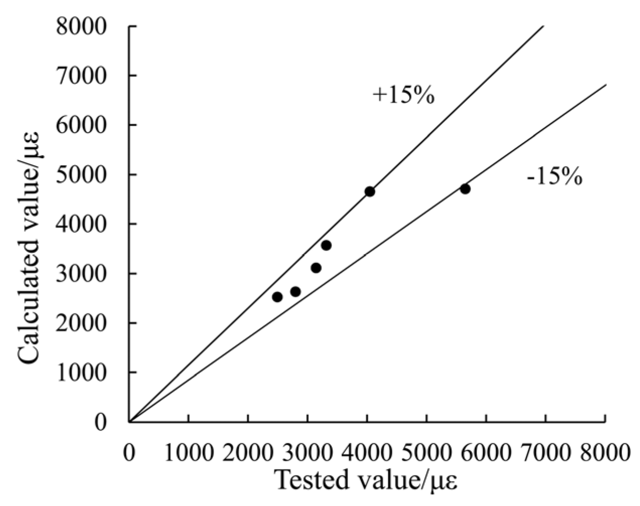
After regression analysis of experimental data containing the six columns, the parameter η is derived as shown in Equation (26). The estimated strain at maximum concrete stress matches well to the test results, as has been shown in
Figure 14.
Figure 14.
A comparison between the estimated values and the tested values of strain at maximum concrete stress.
Figure 14.
A comparison between the estimated values and the tested values of strain at maximum concrete stress.


