The development of the modern industrial history is characterized by the continually increasing operating temperature of the industrial equipment and machineries. The operating temperature changes from about 160 °C in the boiler of the steam engine to 1800 °C in the aircraft engine turbine [
1]. Modern engineering materials are confronted with increasingly strict operating conditions, where complex geometry structure, high operating pressure, high stress state and elevated temperature are challenging the reliability of the material. During the service period, the degradation of material, which includes a change of the microstructure, the gathering of precipitation and carbide spheroidization and coalescence, could result in the premature occurrence of failure. Therefore, the determination of the properties of material at high temperature and the evaluation of residual life are crucial. In addition, these two fields are frequently studied by researchers from all over the world.
Typically, the mechanical behavior of a specific material can be obtained from the conventional uniaxial test. However, in order to carry out the uniaxial test, a large amount of material is needed to make the uniaxial specimen. In situations where there is a need for the evaluation of an in-service component, conventional tests are unable to fulfil this task due to massive destruction to the equipment. The need of a mini-invasive assessing approach advances the development of small sample test techniques. Among all the small sample test techniques, the small punch test is considered as the most promising one since first introduced in the early 1980s by Manaham et al. at MIT [
2], as an effective method to assess the degradation of mechanical properties of materials after nuclear radiation [
3,
4,
5,
6]. To conduct a small punch test, only a small size of material is needed to make the specimen (8–10 mm × 10 mm × 0.5 mm). Such a small size enables evaluating properties of materials un-destructively. J. D. Parker and J. D. James et al. [
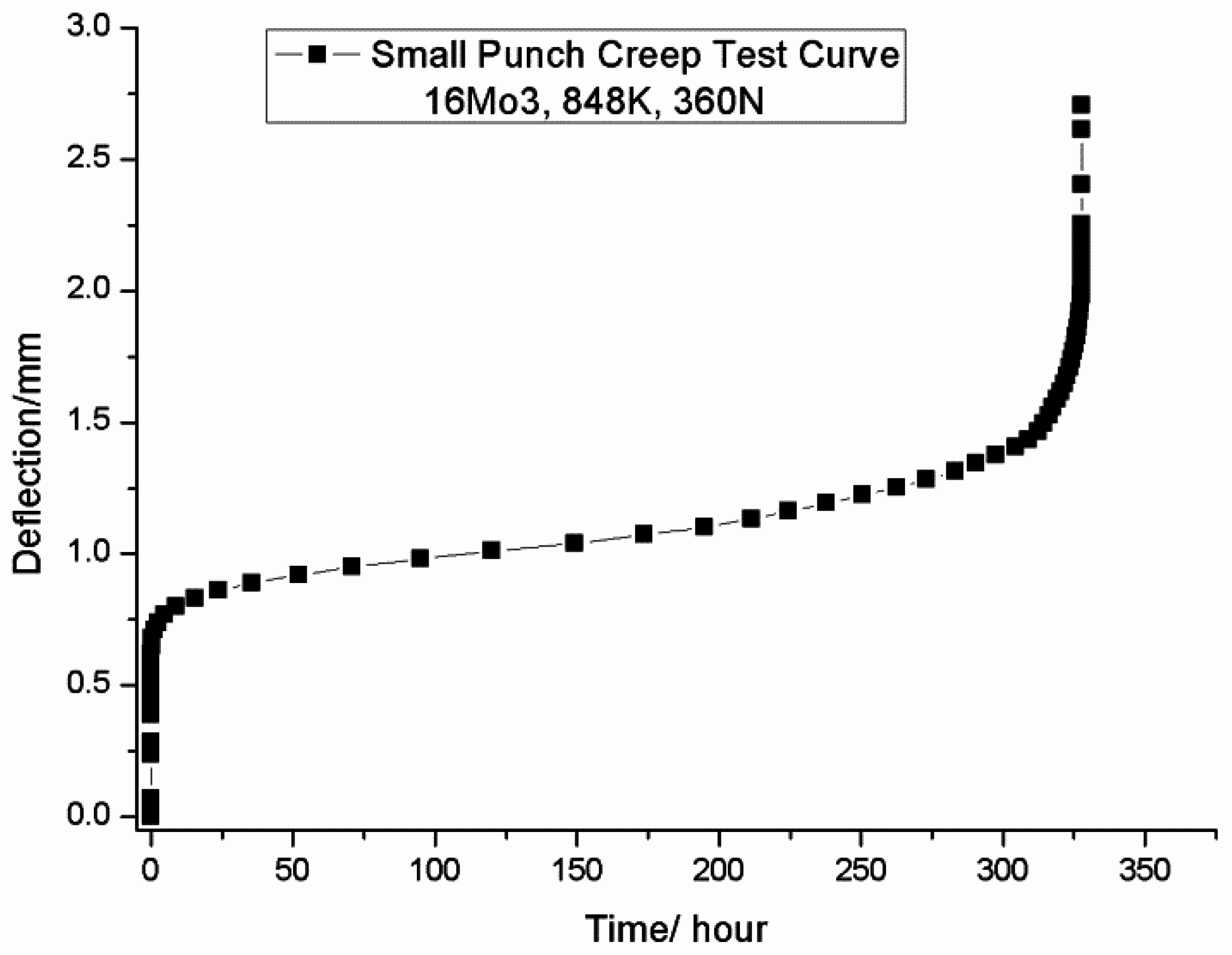
7] pointed out that the small punch test could be applied to obtain the creep properties of materials at an elevated temperature.
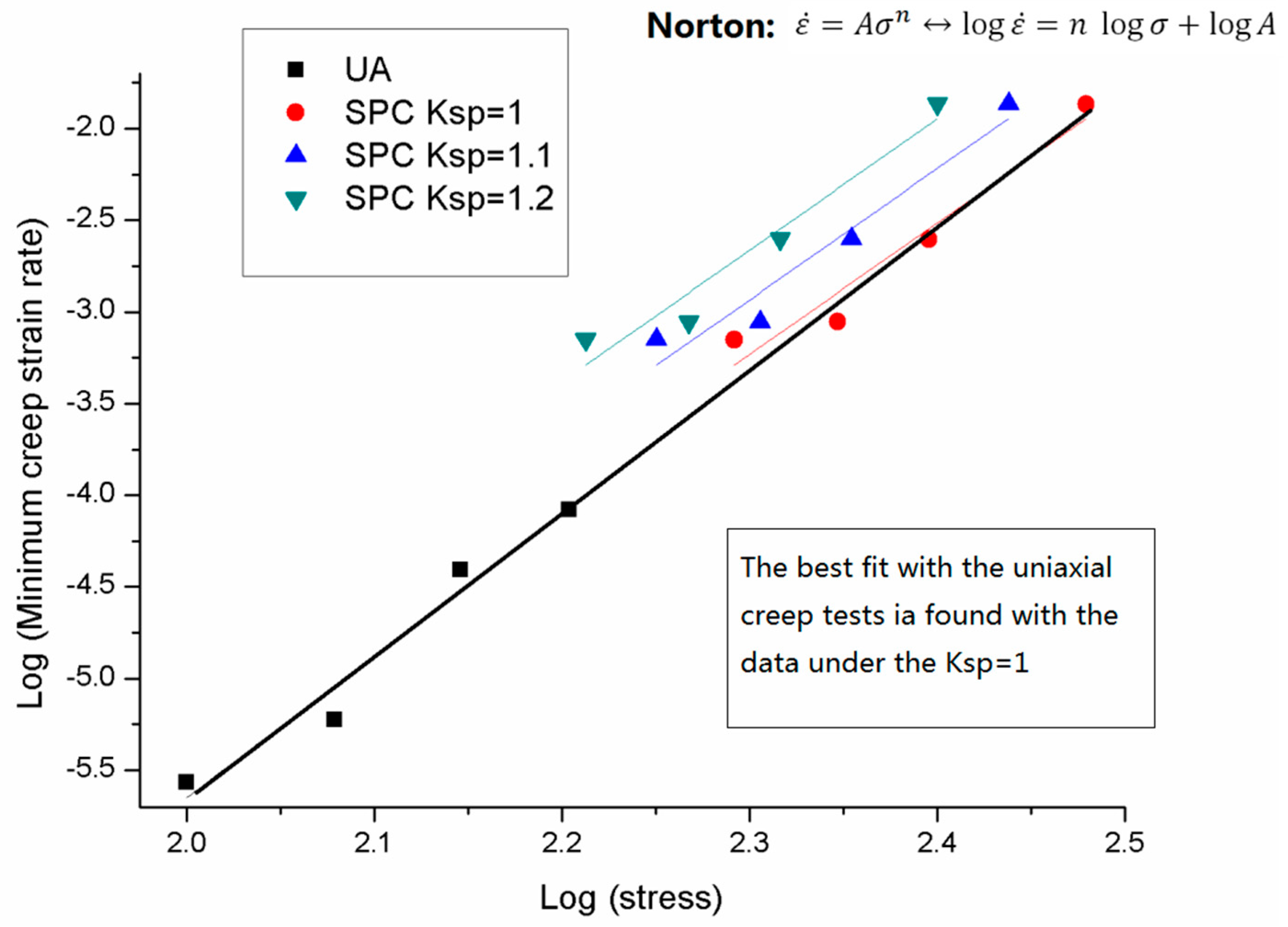
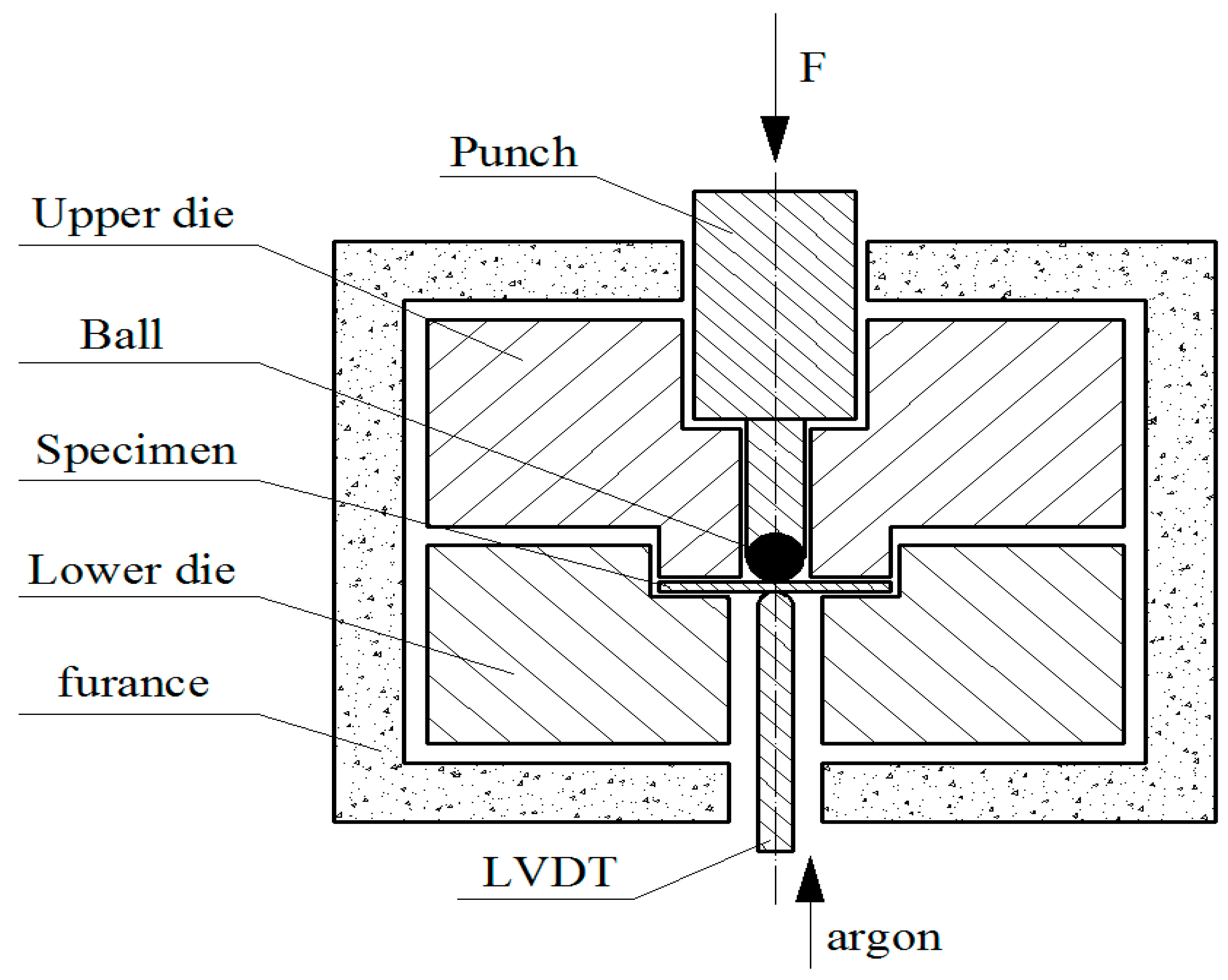
However, it is the conventional uniaxial creep test results, i.e., Norton parameters, which are applied to the engineering design. For the aim of applying the results obtained from the small punch creep test, a correlation needs to be established between the small punch creep test and the uniaxial creep test. In the uniaxial test, the test specimen is only subjected to single stress state, which is tensile stress. While in the small punch creep test, the test specimen bends while the punch ball moves downwards. Thus, in this situation, the punch imposes a three state stress to the test specimen. The discrepancy in stress state leads to the gap between the results of the above two methods.
1.2. Equivalent Stress of the Small Punch Creep Test
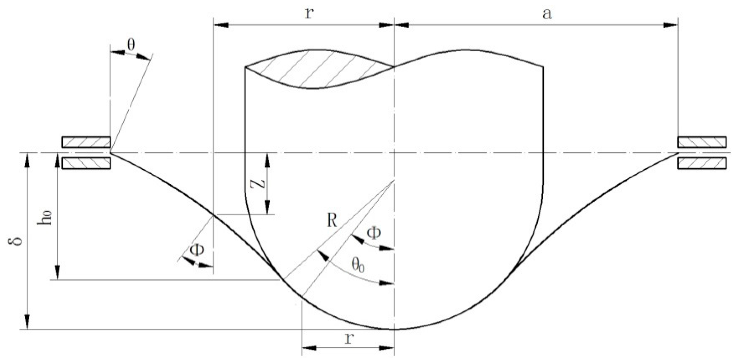
Current studies in the field of the small punch creep test focus on finding out the relationship between the small punch creep test and the uniaxial creep test. With the derived strain from the Chakrabarty model, the other important factor needed is the stress of the small punch creep test. It needs to be noted that the mentioned stress () is not the specific small punch creep test stress. The stress of the small punch specimen varies in different locations; the equivalent stress () is the equivalent uniaxial creep stress. Since the strain and equivalent stress of the small punch test lies in the core of the correlation, a relationship between the applied load Fsp of the small punch test and the equivalent stress () of the uniaxial creep test must be established.
Derived from an equilibrium of the Chakrabarty model and through mathematic deduction, the ratio between load
and equivalent stress
is given as:
where the t stands for the thickness of the specimen.
Yang and Wang [
9] studied the ratio between load F
sp and equivalent stress σ; the following equation was derived:
However, the above Equations (4) and (5) are in inexplicit form; they are either the function of the angle
or the deflection
. Firstly, in 2006, bringing together the previous studies, an explicit form of the equation was introduced by the European standard “Europe Code of Practice: A Code of Practice for Small Punch Creep Testing” [
10]. The equation is expressed as a function of the geometry, where
stands for the radius of the die hole; R stands for the radius of the punch head; t stands for the thickness of the specimen; k
sp is the correlation factor.
The release of the CEN (European Committee for Standardization), small punch creep testing code of practice, facilitated the progress in the field of the small punch creep test. The above Equation (6) was recognized and widely used by many researchers. Blagoeva, Hurst [
11] applied the CEN code to investigate the properties of welded P91 pipe. The creep behavior of the disc specimen was extracted from the weld P91, in which a desirable outcome was achieved. In this paper, for the most commonly used small punch test apparatus both in Europe and China, h = 0.5 mm, R = 1.25 mm and
= 2 mm. Thus, the expression leads to:
Since the ratio between the applied load F
sp and equivalent stress
is expressed in a linear relation, the slope k
sp lies in the key position in Equation (7). The research by Tettamandi and Crudeli [
12] showed that the typical value for F
sp/σ is in the range between 1.95 and 2.06. However, Bicego reported different result that F
sp/σ ≈ 1.87 [
13], In the research of Jeffs [
14], the ksp value of 0.6 and 0.8 was determined for one single crystal material at the temperature of 950 °C and 1050 °C. In the research work of Li [
15] and Feng [
16], the value of k
sp = 1.0 (F
sp/σ = 1.89) was adopted. However, the reasons of adopting this k
sp value were not well addressed. What’s more, the F
sp/σ values adopted by the above researchers are empirical values. Not enough support from the experiment, which combines the uniaxial creep test and the small punch creep test, is found in their work.
Alegre [
17] proposed a method to determine the value of k
sp based on an assumption that the ratio of the applied load F
sp and the equivalent stress
follows a linear relation. The proposed method can be concluded as follows: for the uniaxial creep test at a specific testing temperature, when the applied stress
approaches the creep strength of the material (
), the failure time
approached 0 (
) and the minimum strain rate
approaches
(
). For the small punch creep test, in an experiment of the same material under the same temperature, when the applied load F
sp approaches the maximum load (F
max) of the test condition (F
sp F
max), at this critical moment, the small punch creep failure time
approaches 0 (
) and the small punch minimum strain rate
approaches
(
). Under this condition the value of the correlation factor k
sp can be defined as:
The above method by Alegre may sound reasonable; on the other hand, it is hard to define and measure the failure time when it approaches 0, and to what extent the minimum creep strain rate can be regarded as infinite. What’s more, this method uses the data collected at one single maximum load, which is not representative enough for different loading conditions.
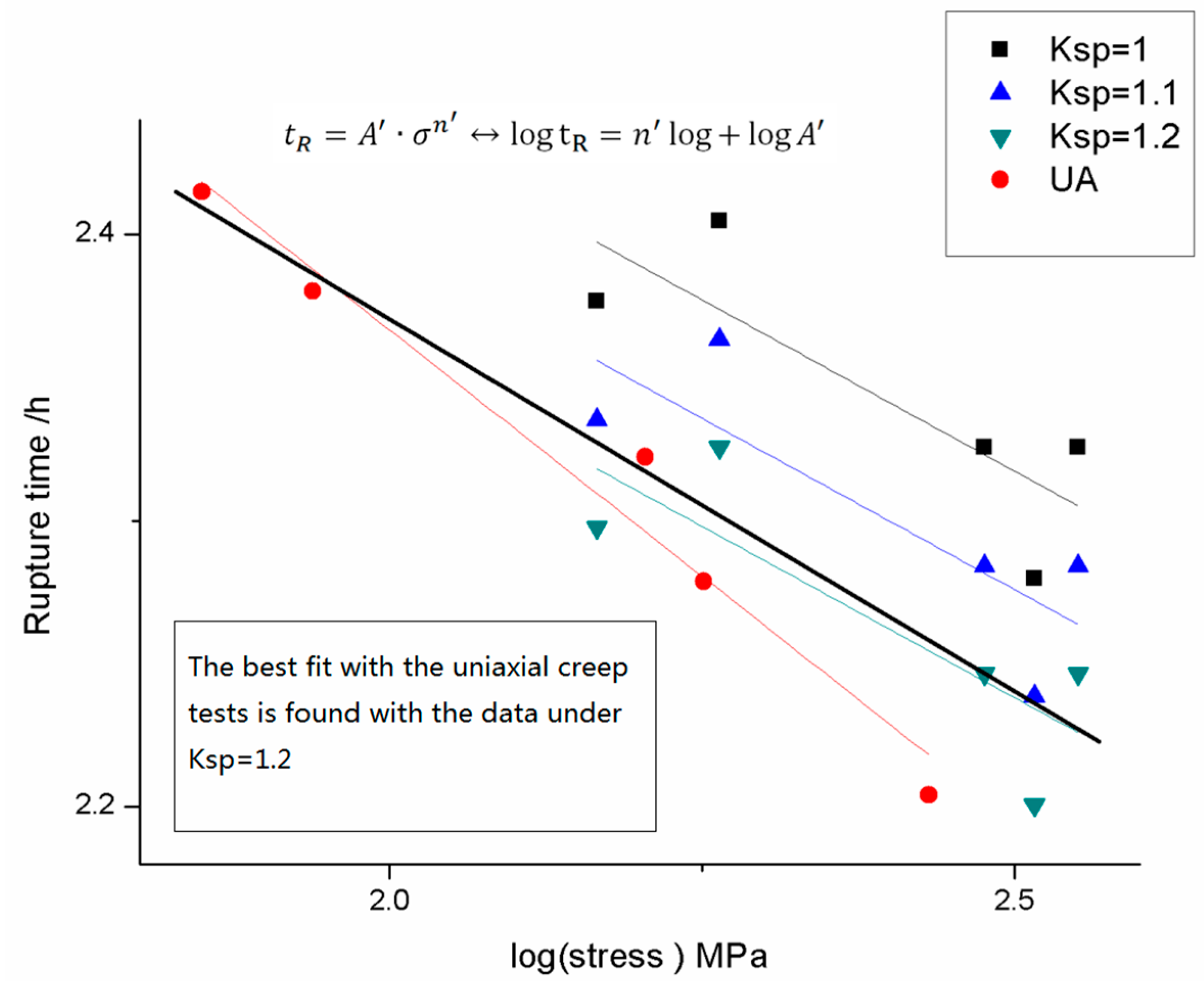
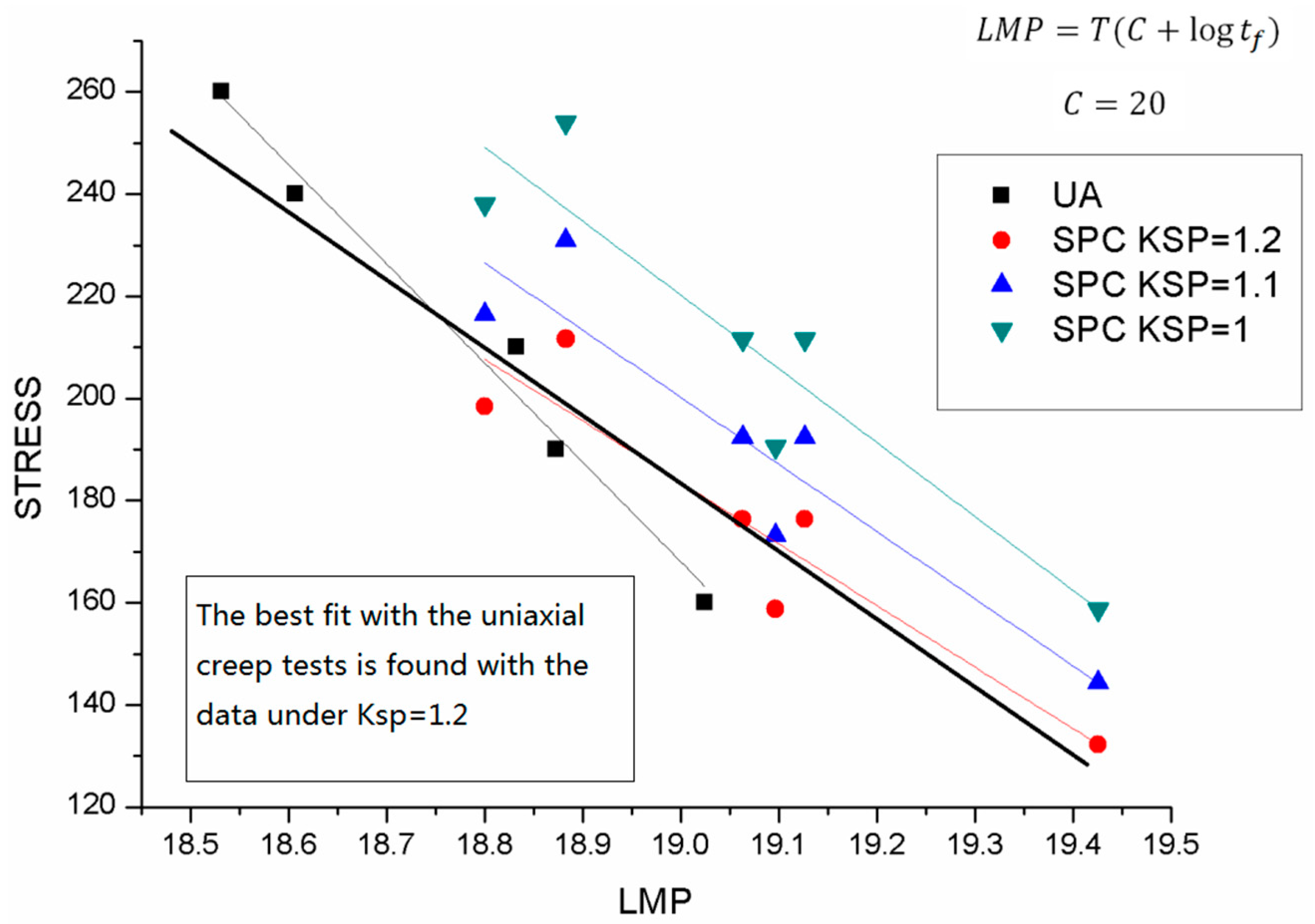
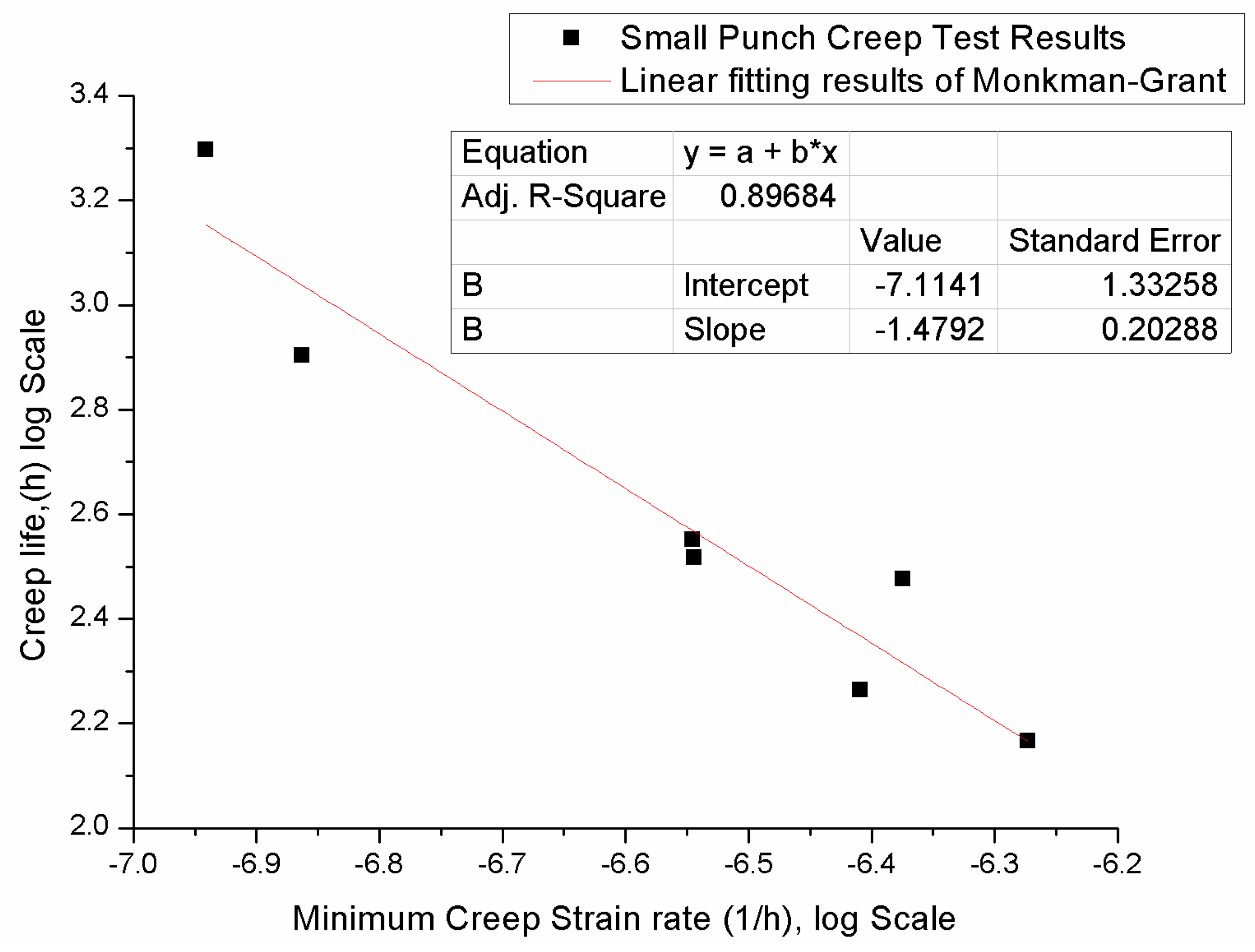
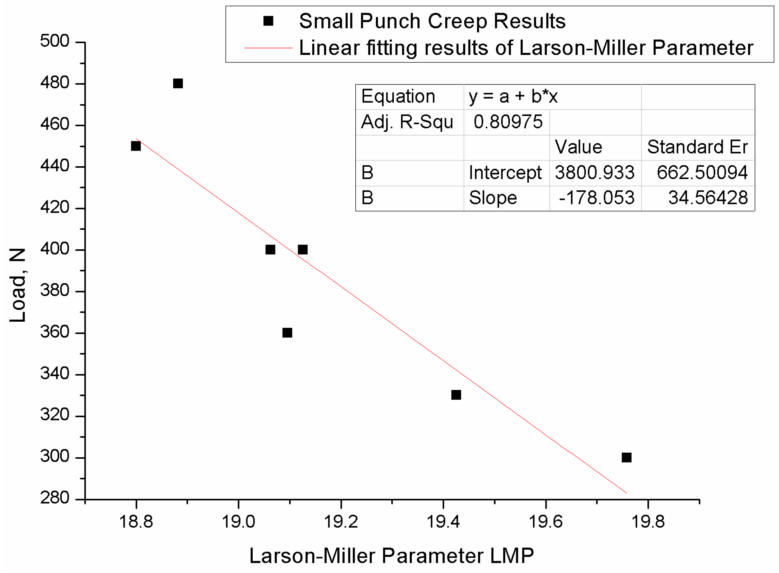
In this paper, a new approach for determining the correlation factor was proposed. Both the small punch creep test and uniaxial creep test experiment was studied and compared. The ksp value of different materials was derived, and suggestions for determining the stress of different materials are given, which provide a useful guidance for the research in the field of the small punch creep test.


