
Disassembly Properties of Cementitious Finish Joints Using an Induction Heating Method

Abstract
:1. Introduction
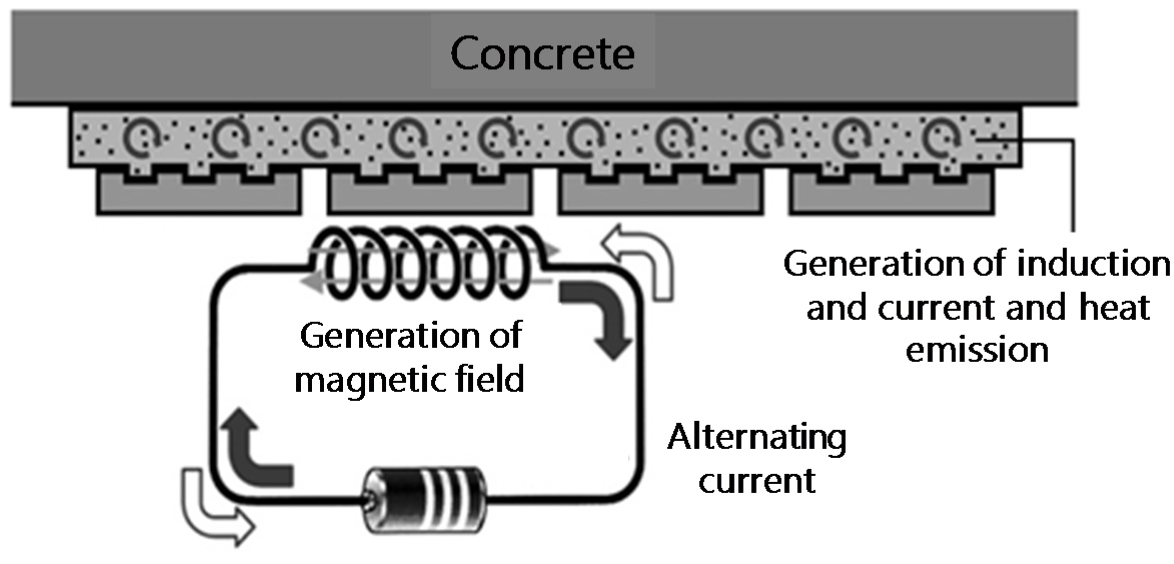
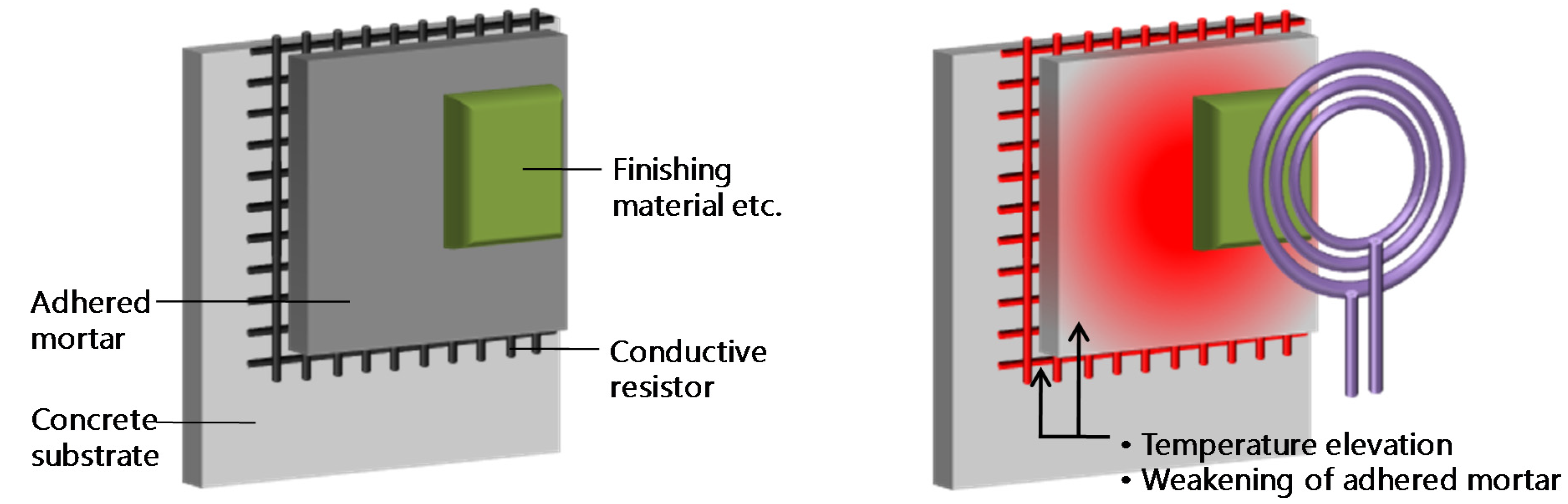
2. Separation Model for Cementitious Joints during Induction Heating
3. Temperature Elevation Characteristics of Conductive Resistors under Induction Heating
3.1. Overview of Experiment
3.2. Experiment Factors

| Specimen Symbol | Conductive Resistor | |
|---|---|---|
| Metal Mesh and Punching Metal | Size | |
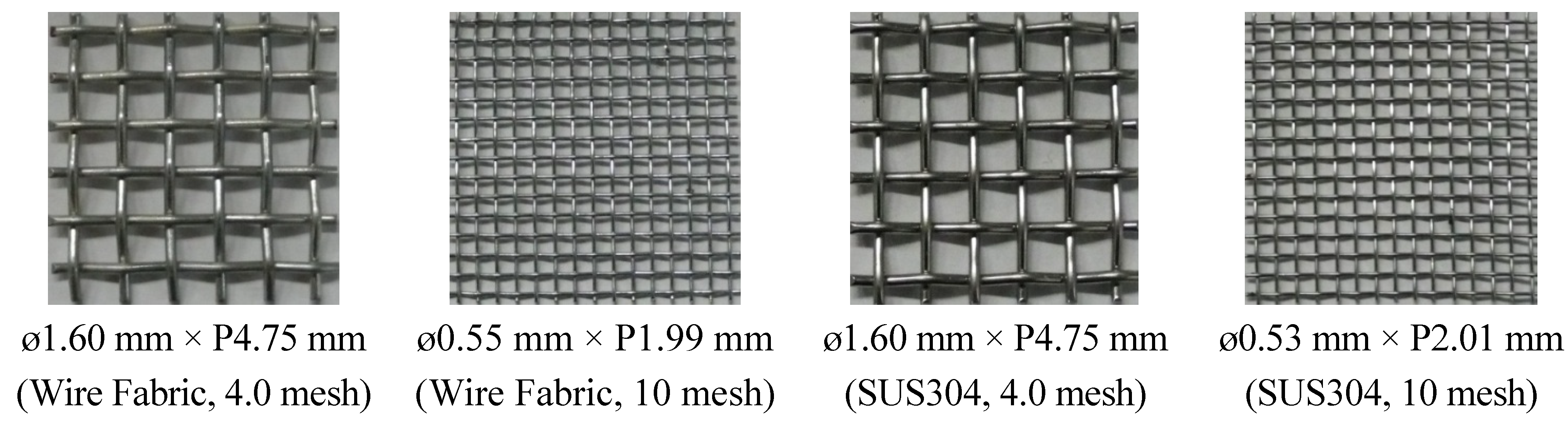
| F4.0 | Wire fabric (zinc plate) | ø1.60 mm × P4.75 mm (4 Mesh) |
| F10 | ø0.55 mm × P1.99 mm (10 Mesh) | |
| S4.0 | Stainless fabric | ø1.60 mm × P4.75 mm (4 Mesh) |
| S10 | ø0.53 mm × P2.01 mm (10 Mesh) | |
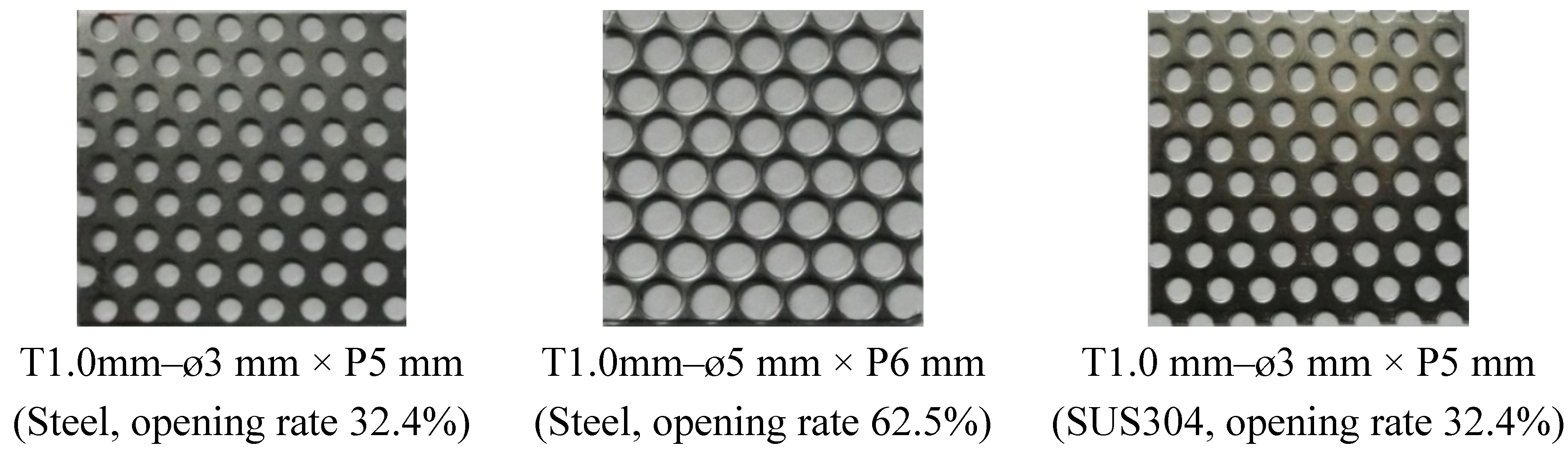
| Fp0.5–ø3 | Steel punching metal | T0.5 mm–ø3 mm × P5 mm (Opening rate 32.4%) |
| Fp1.0–ø3 | T1.0 mm–ø3 mm × P5 mm (Opening rate 32.4%) | |
| Fp1.0–ø5 | T1.0 mm–ø5 mm × P6 mm (Opening rate 62.5%) | |
| Sp0.5–ø3 | Stainless punching metal | T0.5 mm–ø3 mm × P5 mm |
| Sp1.0–ø3 | T1.0 mm–ø3 mm × P5 mm | |
3.3. Production of Materials and Specimen
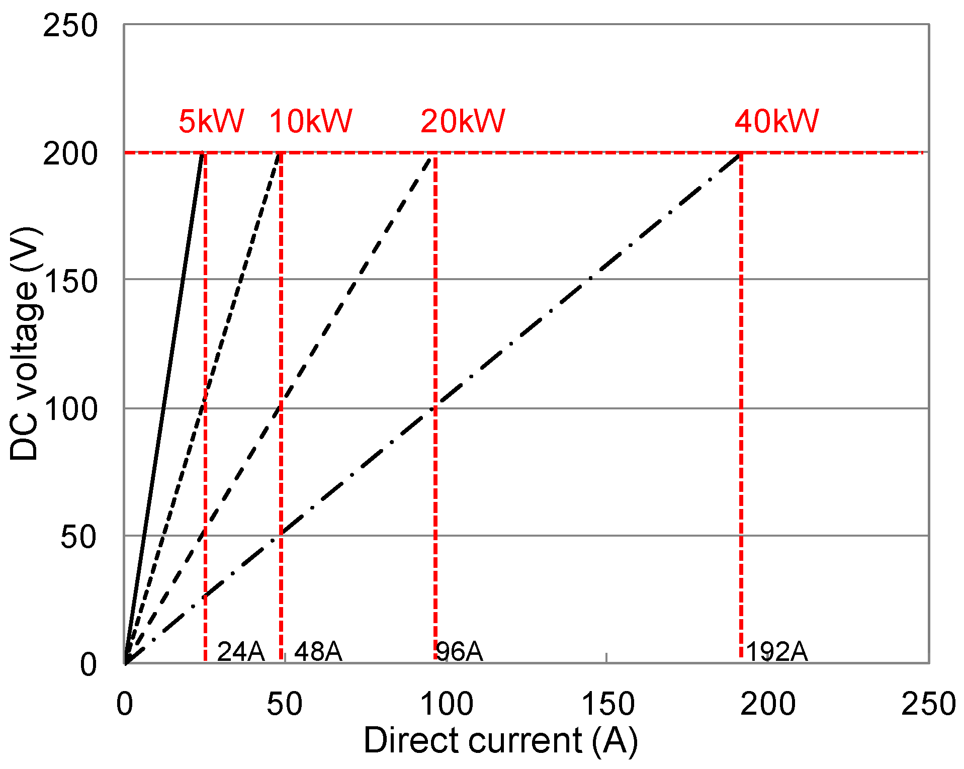
3.4. Induction Heating
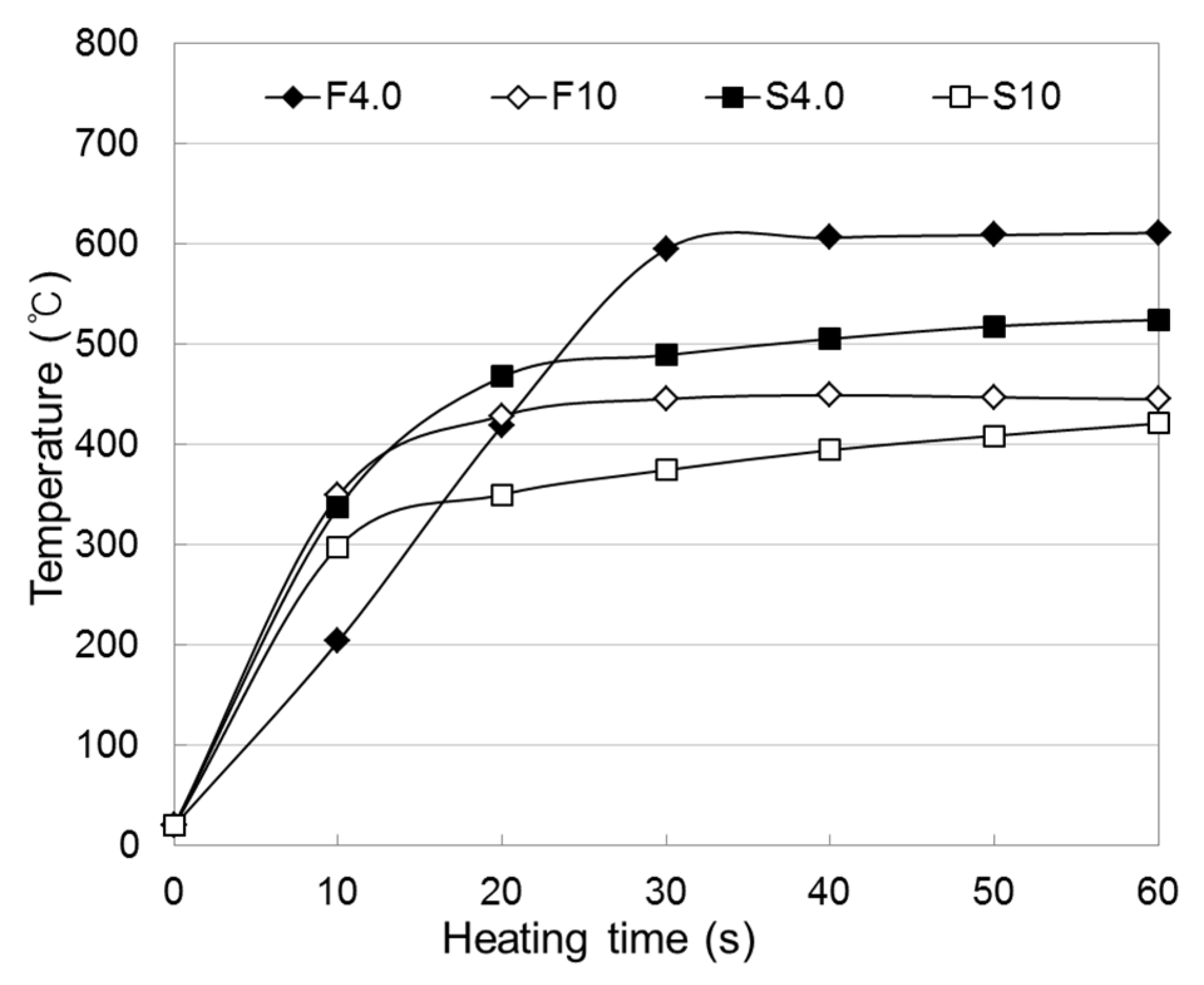
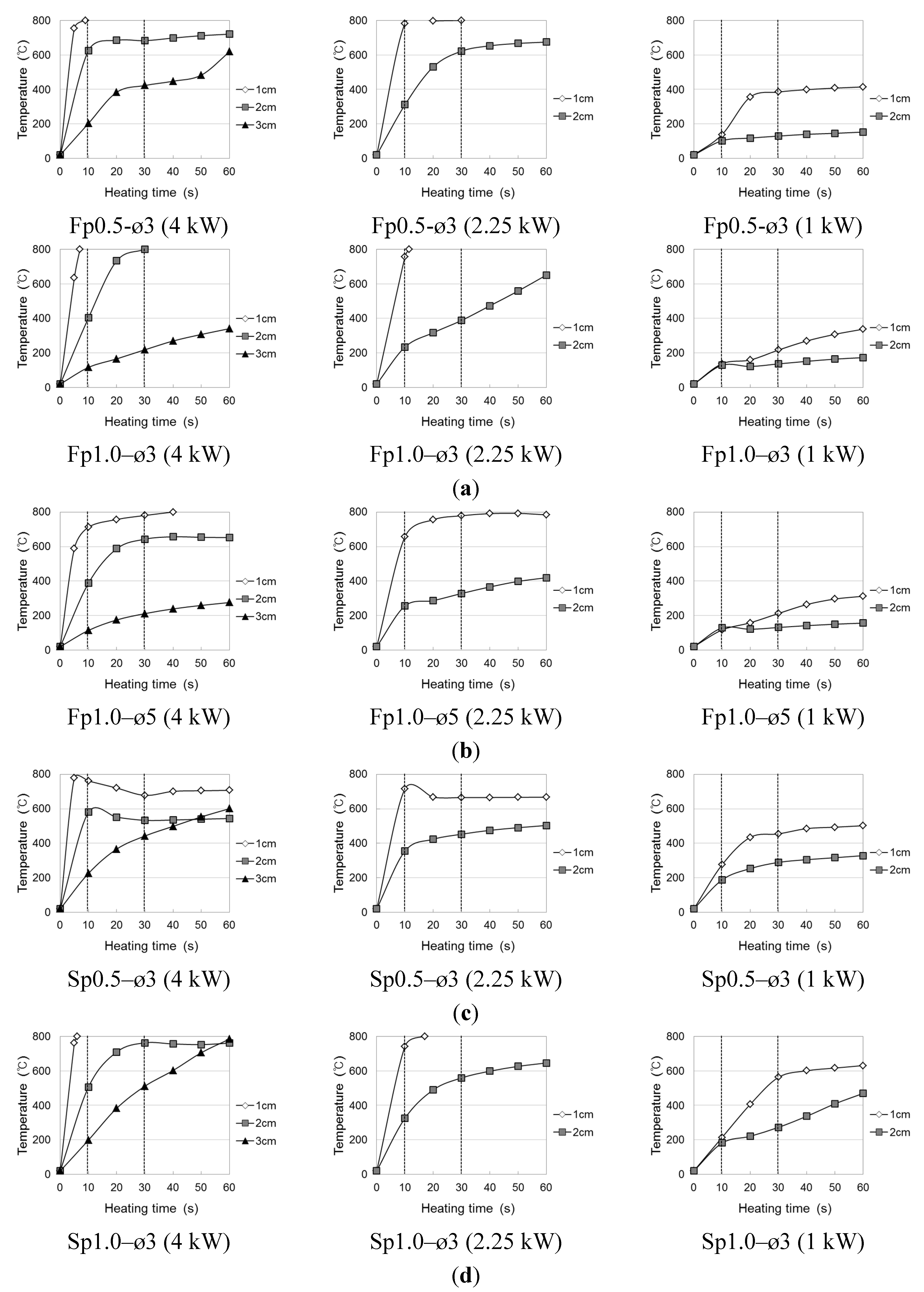
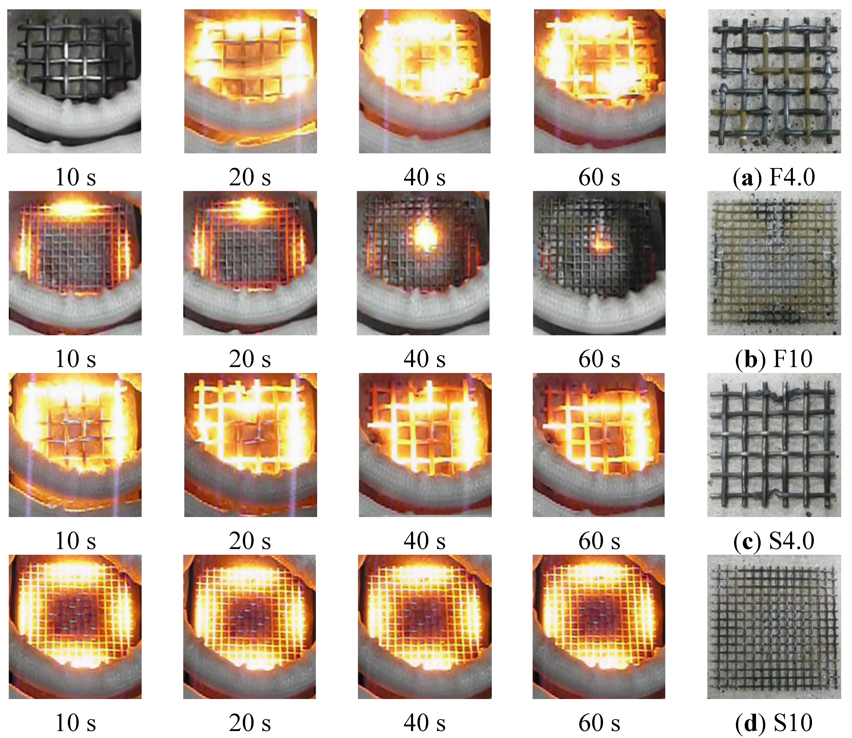
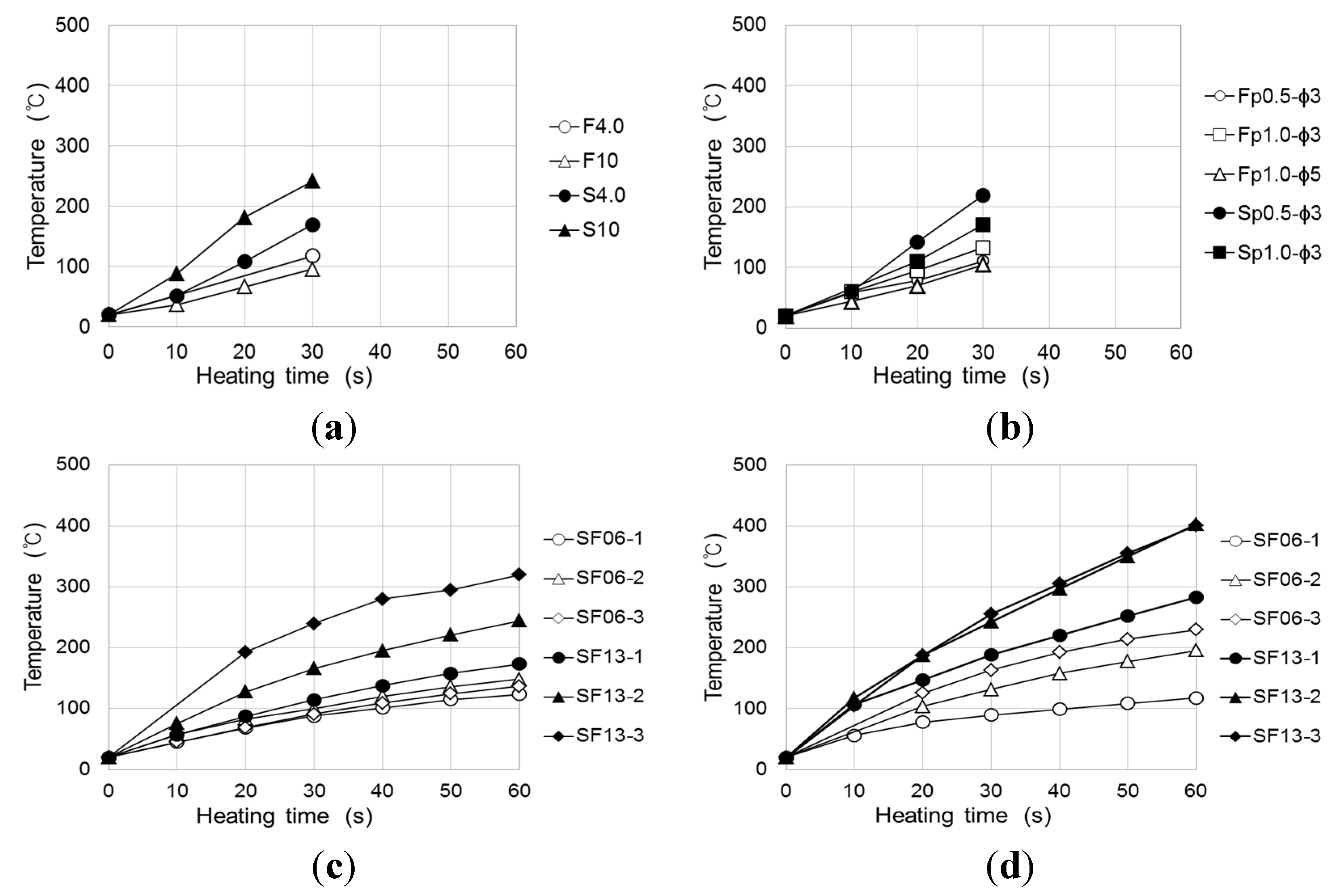
3.5. Temperature Elevation Characteristics of Conductive Resistor by Induction


4. Evaluation of Disassembly Properties of a Cementitious Joint during Induction Heating
4.1. Overview of Experiment
| Specimen Symbol | Conductive Resistor | |
|---|---|---|
| Conductive Resistor Shape | Specification | |
| N | - | - |
| F4.0 | Wire Fabric (zinc plated) | Diameter 1.60 mm × P4.75 mm (4 Mesh) |
| F10 | Diameter 0.55 mm × P1.99 mm (10 Mesh) | |
| S4.0 | Stainless fabric (SUS304) | ø1.60 mm × P4.75 mm (4 Mesh) |
| S10 | ø0.53 mm × P2.01 mm (10 Mesh) | |
| Fp0.5–ø3 | Steel punching metal | T0.5 mm–ø3 mm × P5 mm |
| Fp1.0–ø3 | T1.0 mm–ø3 mm × P5 mm | |
| Fp1.0–ø5 | T1.0 mm–ø5 mm × P6 mm | |
| Sp0.5–ø3 | Stainless punching metal | T0.5 mm–ø3 mm × P5 mm |
| Sp1.0–ø3 | T1.0 mm–ø3 mm × P5 mm | |
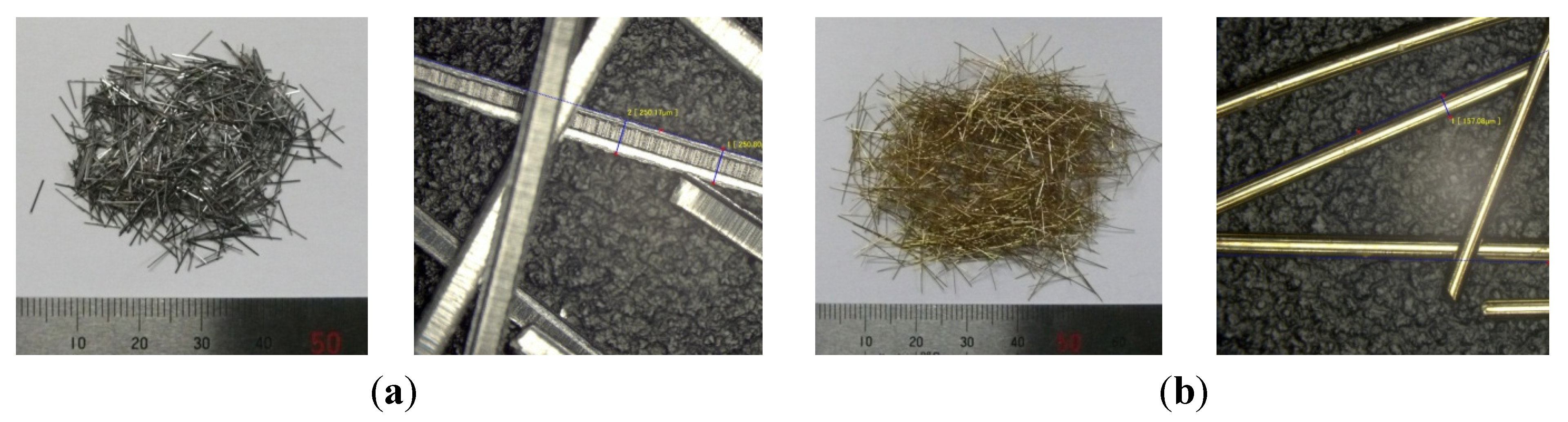
| SF06–* | Steel fiber 6 mm | *: contents rate (1%, 2%, 3%) |
| SF13–* | Steel fiber 13 mm | |
4.2. Production of Materials and Specimens
| Steel Fiber Volume Mixed Rate (Vf) | Cementitious Binder (kg) | |||||
|---|---|---|---|---|---|---|
| Water | Cement | Polymer | Antifoaming Agent | Thickener | Chemical Agent | |
| 0.0 | 0.35 | 1 | 0.1 | 0.001 | - | - |
| 1.0, 2.0 | 0.40 | 1 | 0.1 | 0.001 | - | - |
| 3.0 | 0.40 | 1 | 0.1 | 0.001 | 0.002 * | 0.015 ** |
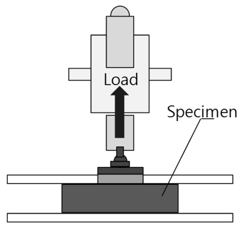
4.3. Experimental Method

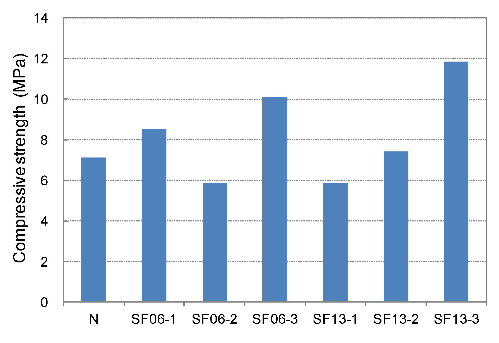
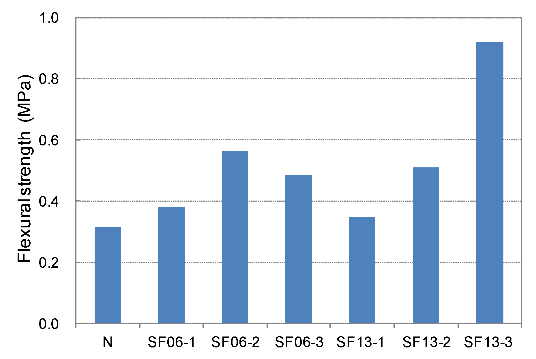
4.4. Analysis of Assembly Property of Cementitious Joint with Conductive Resistor

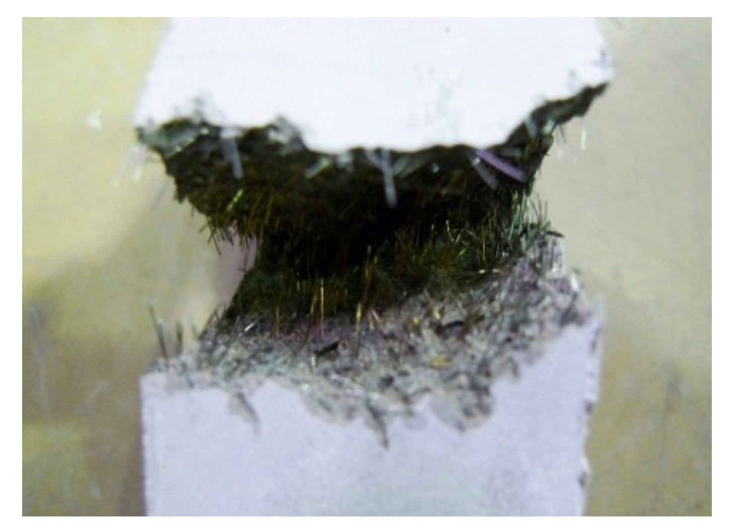


4.5. Evaluation of Disassembly Properties through Induction Heating of a Cementitious Joint with a Conductive Resistor
4.5.1. Changes in Surface Temperature of Mortar Mixed with Steel Fiber through Induction Heating
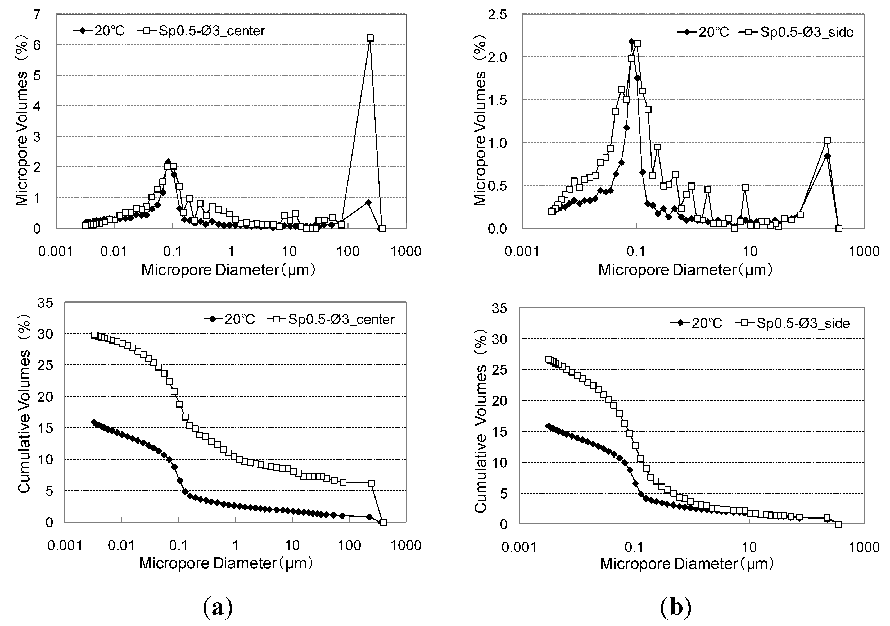
4.5.2. Changes in Pore Structure of the Cementitious Joint
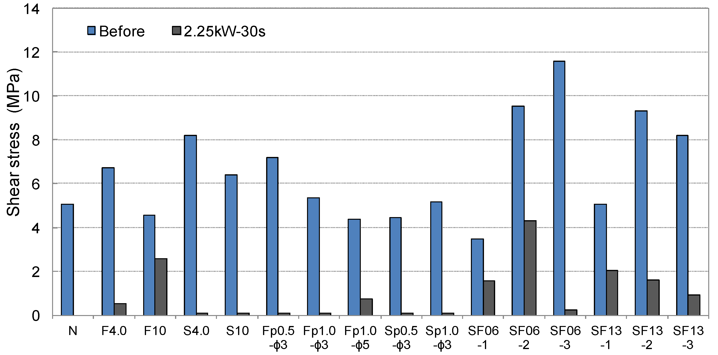
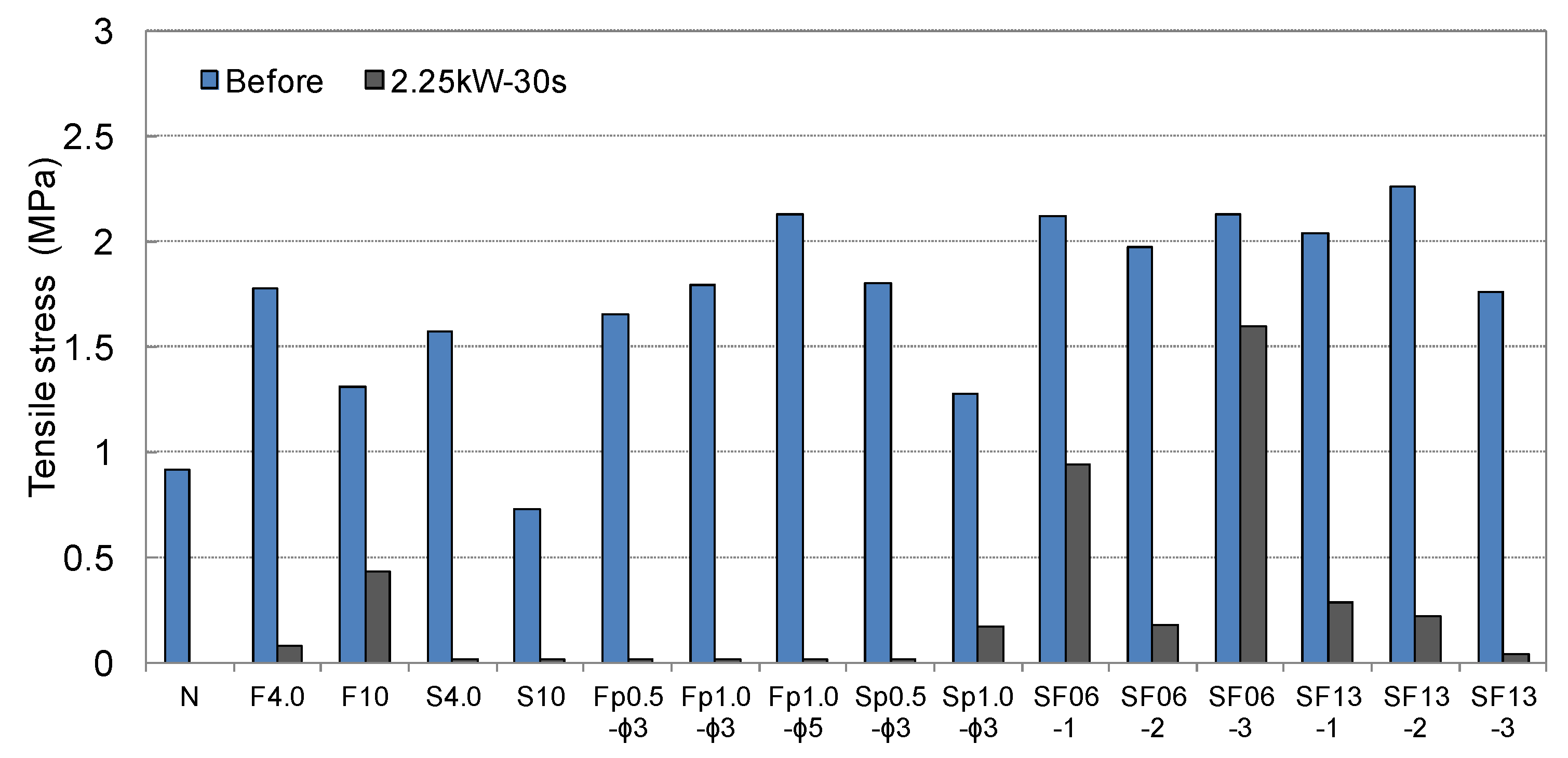
4.5.3. Evaluation of Disassembly Property through Residual Bond Strength after Induction Heating

5. Conclusions
- (1)
- Cementitious joints with conductive resistors showed assembly properties equivalent to or more outstanding than those of ordinary finishing items for joint mortar.
- (2)
- Among the conductive resistors, stainless steel showed more uniform temperature elevation characteristics than wire. Furthermore, punching metal readily caused internal eddy currents and showed the most pronounced disassembly properties by the weakening of cementitious joints.
- (3)
- The temperature elevation and weakening of cementitious joints by induction heating were significantly affected by the radio frequency power from the heating induction coil and the distance of the conductive resistor from the heating induction coil.
- (4)
- Conductive resistors could be selected in many ways, depending on the shape and environment of the joint material and the joint shape in each part of a building. The most appropriate conductive resistors for mortar-weakening by thermal conduction were those with at least 10-mesh wire intervals; no deterioration of the adhesion strength was observed when metal mesh was used. In the case of punching metal, a wide interface presumably formed between the adhered mortars, which thus undermined the assembly performance. Therefore, the use of punching metal with diameters of ø5 mm or greater was deemed preferable for the assembly and disassembly properties. Additionally, when SF13 was mixed at a rate of 2% or more, the disassembly performance was outstanding.
- (5)
- Cementitious joints could be disassembled by manual induction heating at 2.25 kW for 30 s. In this case, 1659 W·h disassembly energy was used and 0.921 kg-CO2 emission was estimated by using the IH method. Moreover, because such joints have the advantage of being reusable by completely disassembling the materials and parts, induction heating is an appropriate method for disassembling parts that require recycling and the reuse of high-priced materials.
Acknowledgments
Author Contributions
Conflicts of Interest
References
- Tsujino, M.; Noguchi, T.; Tamura, M.; Kanematsu, M.; Maruyama, I. Application of Conventionally recycled coarse aggregate to concrete structure by surface modification treatment. J. Adv. Concr. Technol. 2007, 5, 13–25. [Google Scholar] [CrossRef]
- Noguchi, T.; Kitagaki, R.; Nagai, H.; Tsujino, M. Completely recyclable concrete of aggregate-recovery type by using microwave heating technology. In Proceedings of the 2nd International RILEM Conference on Progress of Recycling in the Built Environment, Sao Paulo, Brazil, 2–4 December 2009; pp. 333–343.
- Kobayashi, K.; Mamiya, T.; Inoue, T. Issues and evaluation of environmental load of building demolition waste disposal: Clarificaiton of issues a quantitive influence evaluation based on field survey. J. Environ. Eng. 2004, 582, 115–121. [Google Scholar]
- Choi, J.C.; Park, H.J.; Kim, B.M. The influence of induction heating on the microstructure of A356 for semi-solid forging. J. Mater. Process. Technol. 1999, 87, 46–52. [Google Scholar] [CrossRef]
- Favennec, Y.; Labbé, V.; Bay, F. Induction heating processes optimization a general optimal control approach. J. Comput. Phys. 2003, 187, 68–94. [Google Scholar] [CrossRef]
- Liu, Q.; Schlangen, E.; García, A.; Ven, M. Induction heating of electrically conductive porous asphalt concrete. Constr. Build. Mater. 2010, 24, 1207–1213. [Google Scholar] [CrossRef]
- Liu, Q.; Schlangen, E.; Ven, M.; Bochove, G.; Montfort, J. Evaluation of the induction healing effect of porous asphalt concrete through four point bending fatigue test. Constr. Build. Mater. 2012, 29, 403–409. [Google Scholar] [CrossRef]
- Liu, Q.; García, A.; Schlangen, E.; Ven, M. Induction healing of asphalt mastic and porous asphalt concrete. Constr. Build. Mater. 2011, 25, 3746–3752. [Google Scholar] [CrossRef]
- Schneider, U. Verhalten von Beton bei hohen Temperaturen-Behaviour of Concrete at High Temperatures, Deutscher Ausschuss fur Stahlbeton, Heft 337; Vertrieb Durch Verlag von Wilhelm Ernst & Sohn: Berlin, Germany, 1982; pp. 13–61. [Google Scholar]
- Hirokazu, S.; Kazumi, K.; Kouichi, H.; Yasuo, K. Development of recovering technology of high quality aggregate from demolished concrete with heat and rubbing method. Proc. Jpn. Concr. Inst. 2000, 22, 1093–1110. [Google Scholar]
- Garcıa, A.; Schlangen, E.; van de Ven, M.; van Vliet, D. Induction heating of mastic containing conductive fibers and fillers. Mater. Struct. 2011, 44, 499–508. [Google Scholar] [CrossRef]
- Rudolf, R.; Mitschang, P.; Neitzel, M. Induction heating of continuous carbon fibre reinforced thermoplastics. Compos. Pt. A-Appl. Sci. Manuf. 2000, 31, 1191–1202. [Google Scholar] [CrossRef]
- Ahn, J. Microwave dielectric heating to disassemble a modified cementitious joint. Mater. Struct. 2013, 46, 2077–2090. [Google Scholar] [CrossRef]
© 2015 by the authors; licensee MDPI, Basel, Switzerland. This article is an open access article distributed under the terms and conditions of the Creative Commons Attribution license (http://creativecommons.org/licenses/by/4.0/).
Share and Cite
Ahn, J.; Noguchi, T.; Kitagaki, R. Disassembly Properties of Cementitious Finish Joints Using an Induction Heating Method. Materials 2015, 8, 2433-2453. https://doi.org/10.3390/ma8052433
Ahn J, Noguchi T, Kitagaki R. Disassembly Properties of Cementitious Finish Joints Using an Induction Heating Method. Materials. 2015; 8(5):2433-2453. https://doi.org/10.3390/ma8052433
Chicago/Turabian StyleAhn, Jaecheol, Takafumi Noguchi, and Ryoma Kitagaki. 2015. "Disassembly Properties of Cementitious Finish Joints Using an Induction Heating Method" Materials 8, no. 5: 2433-2453. https://doi.org/10.3390/ma8052433