
Additively Manufactured Open-Cell Porous Biomaterials Made from Six Different Space-Filling Unit Cells: The Mechanical and Morphological Properties


 ,
, 
Abstract
:1. Introduction
2. Materials and Methods
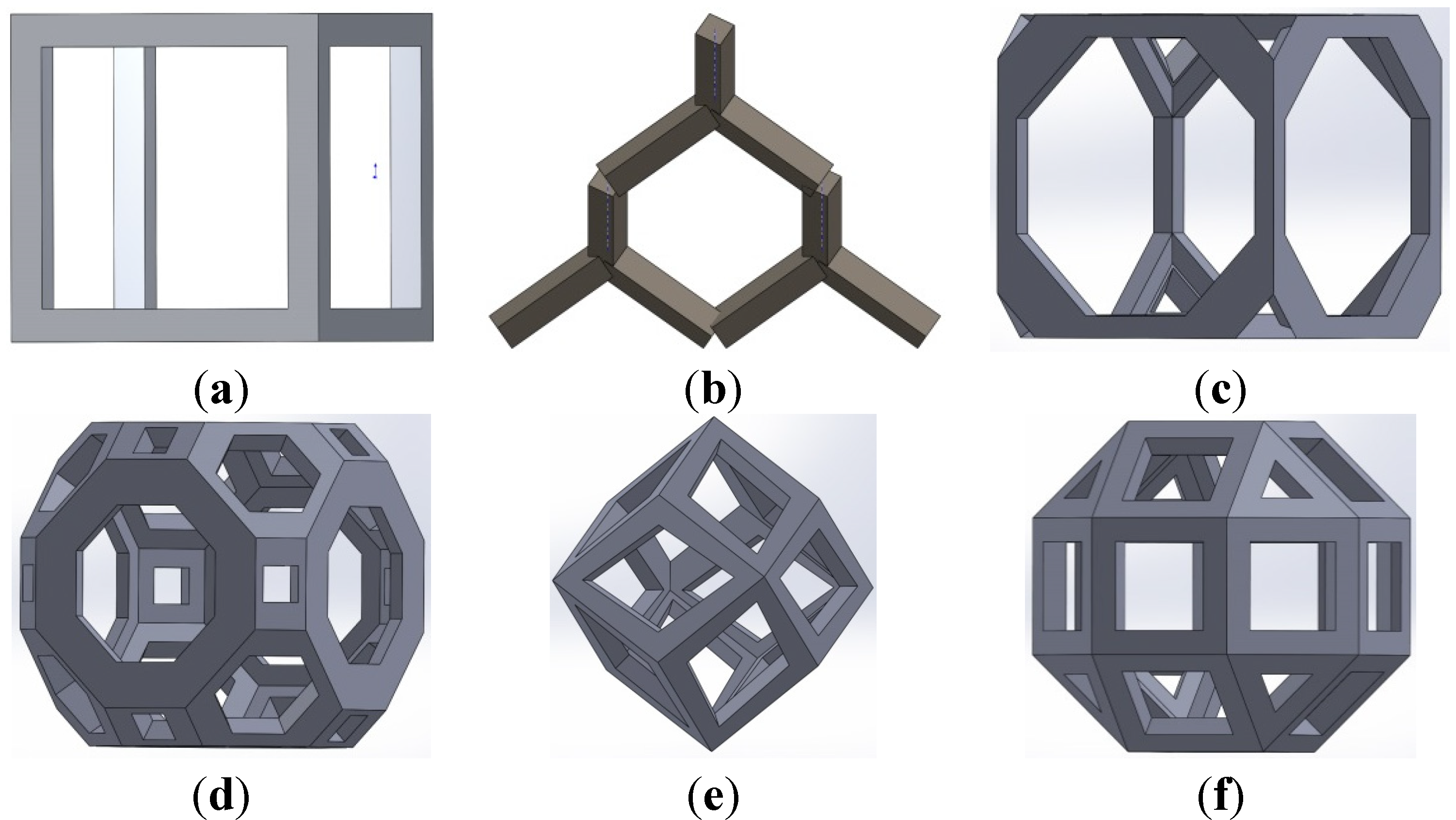
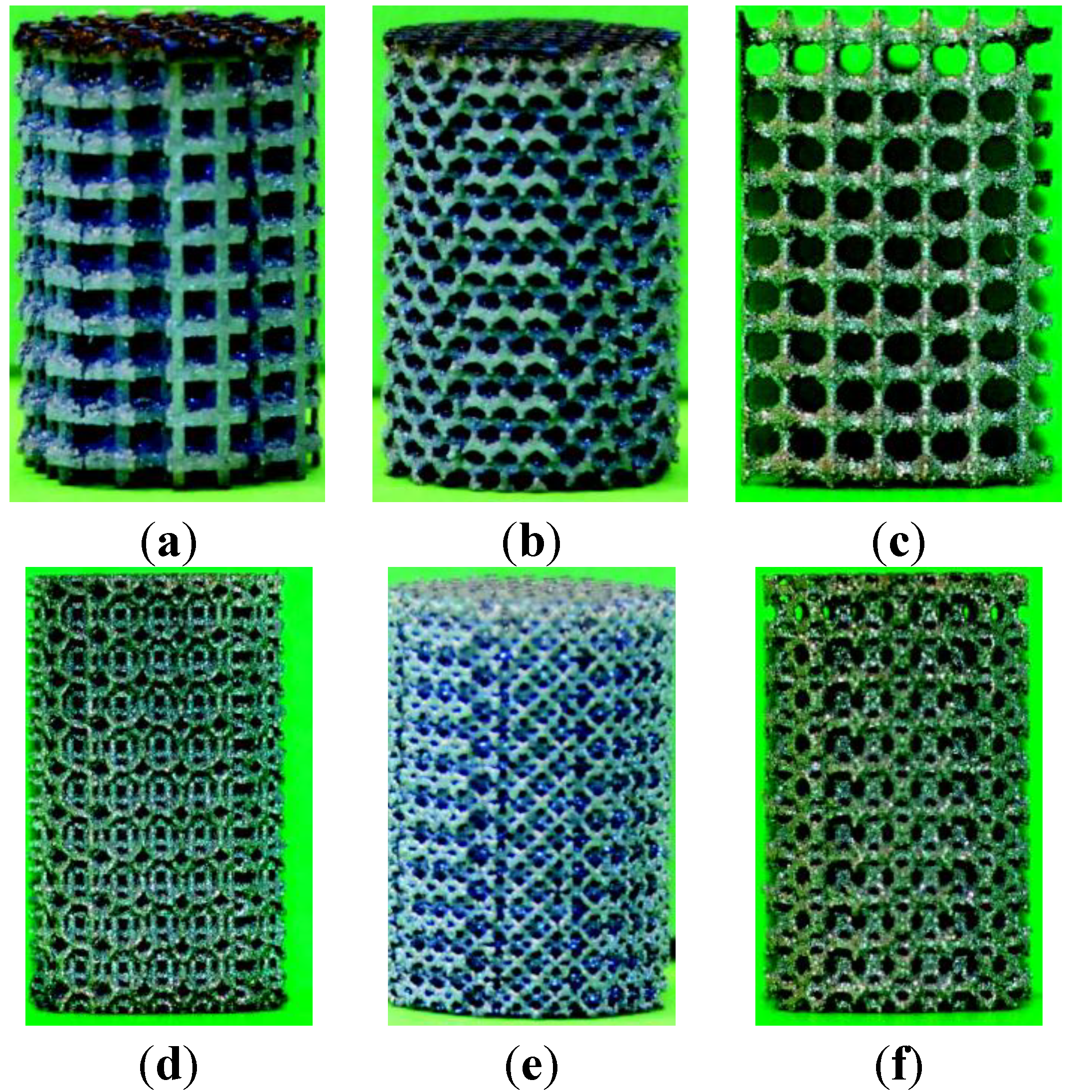
2.1. Materials and Manufacturing

| Strut Diameter (μm) | Pore Size (μm) | |||
|---|---|---|---|---|
| Nominal (Design) | μCT (SD) | Nominal (Design) | μCT (SD) | |
| Cubic (C) | ||||
| C-1 | 348 | 451 (147) | 1452 | 1413 (366) |
| C-2 | 540 | 654 (190) | 1260 | 1139 (359) |
| C-3 | 612 | 693 (200) | 1188 | 1155 (354) |
| C-4 | 720 | 823 (230) | 1080 | 1020 (311) |
| Diamond (D) | ||||
| D-1 | 277 | 240 (46) | 923 | 958 (144) |
| D-2 | 450 | 416 (65) | 750 | 780 (141) |
| D-3 | 520 | 482 (70) | 680 | 719 (130) |
| D-4 | 600 | 564 (76) | 600 | 641 (137) |
| Truncated Cube (TC) | ||||
| TC-1 | 180 | 331 (76) | 1720 | 1625 (398) |
| TC-2 | 240 | 363 (80) | 1660 | 1615 (392) |
| TC-3 | 304 | 395 (88) | 1596 | 1593 (382) |
| TC-4 | 380 | 463 (126) | 1520 | 1535 (370) |
| TC-5 | 460 | 568 (183) | 1440 | 1497 (360) |
| TC-6 | 530 | 620 (200) | 1370 | 1426 (357) |
| Truncated Cubeoctahedron (TCO) | ||||
| TCO-1 | 324 | 350 (60) | 876 | 862 (349) |
| TCO-2 | 460 | 416 (64) | 1040 | 1142 (383) |
| TCO-3 | 520 | 452 (65) | 980 | 1098 (386) |
| TCO-4 | 577 | 482 (70) | 923 | 1079 (391) |
| TCO-5 | 621 | 516 (82) | 862 | 1065 (361) |
| TCO-6 | 693 | 564 (76) | 807 | 1049 (383) |
| Rhombicdodecahdron (RD) | ||||
| RD-1 | 250 | 246 (53) | 1250 | 1299 (449) |
| RD-2 | 310 | 305 (97) | 1190 | 1224 (455) |
| RD-3 | 370 | 440 (126) | 1130 | 1168 (364) |
| RD-4 | 430 | 461 (163) | 1070 | 1305 (554) |
| RD-5 | 490 | 430 (122) | 1010 | 920 (300) |
| RD-6 | 550 | 506 (144) | 950 | 1058 (356) |
| Rhombic Cubeoctahedron (RCO) | ||||
| RCO-1 | 380 | 348 (59) | 820 | 877 (355) |
| RCO-2 | 410 | 369 (59) | 790 | 847 (349) |
| RCO-3 | 440 | 486( 113) | 760 | 1089 (402) |
| RCO-4 | 470 | 437 (61) | 730 | 754 (359) |
| RCO-5 | 500 | 539 (120) | 700 | 1043 (401) |
| RCO-6 | 530 | 438 (61) | 670 | 794 (368) |
2.2. Morphological Characterization
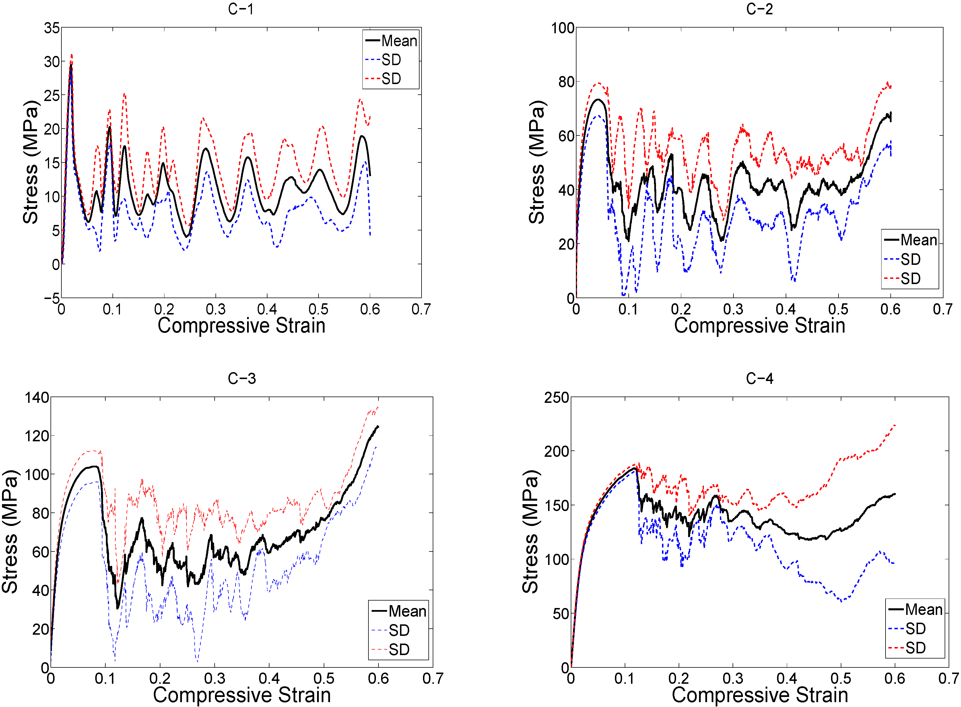
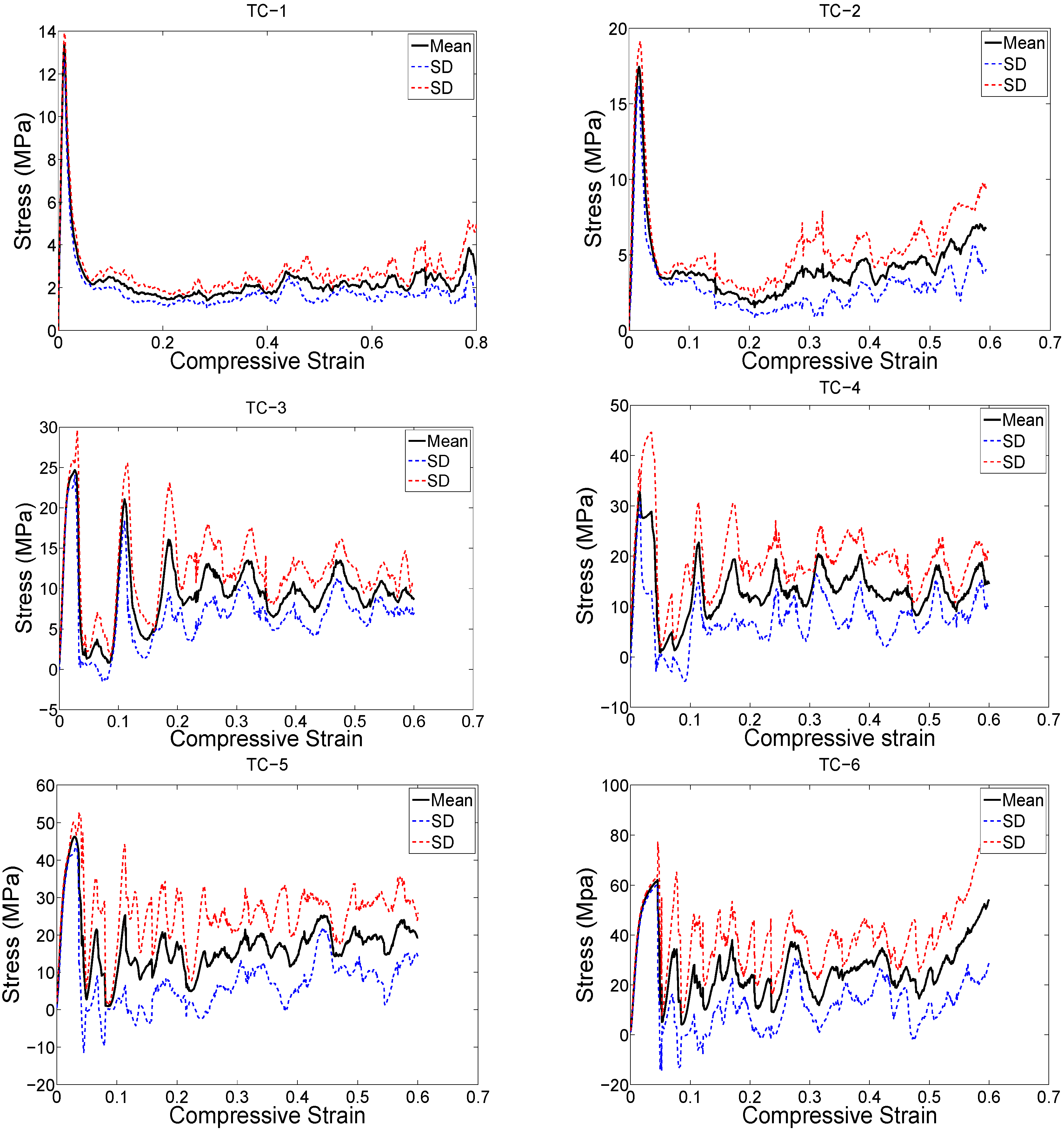
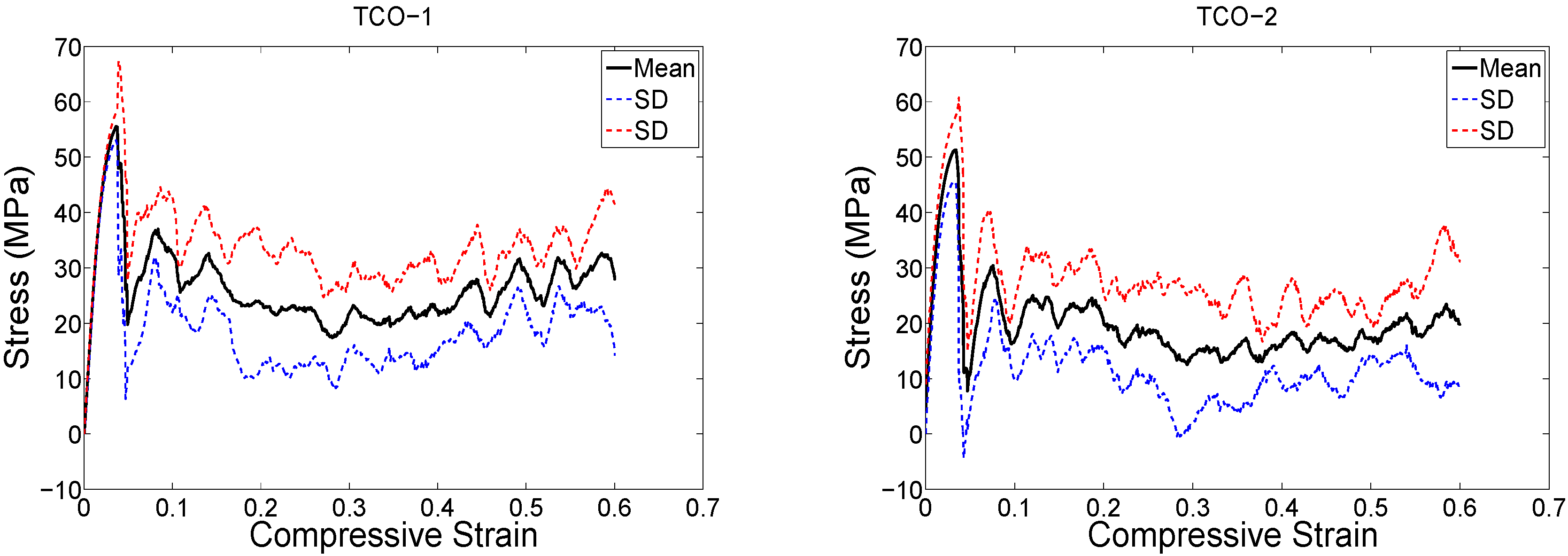
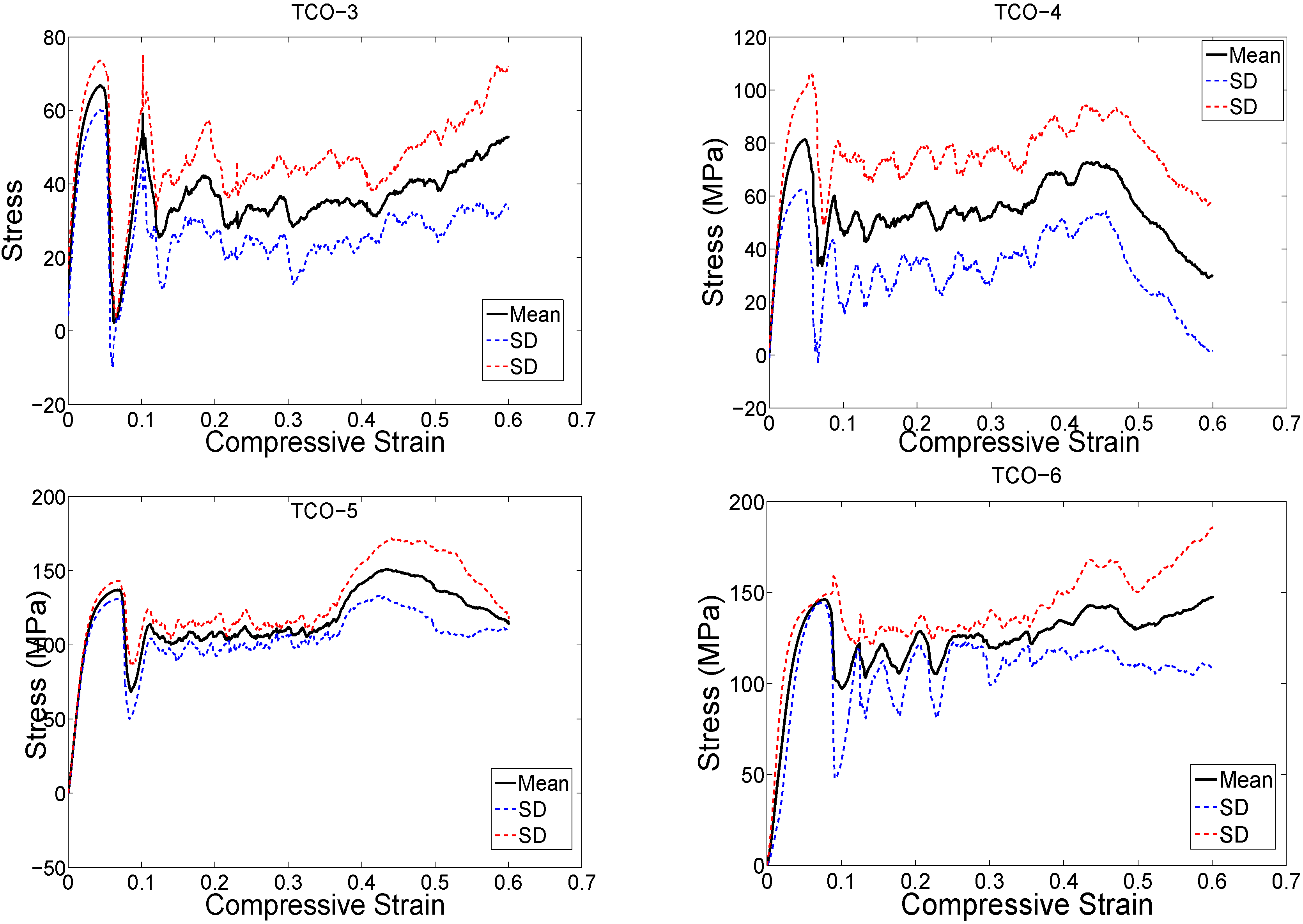
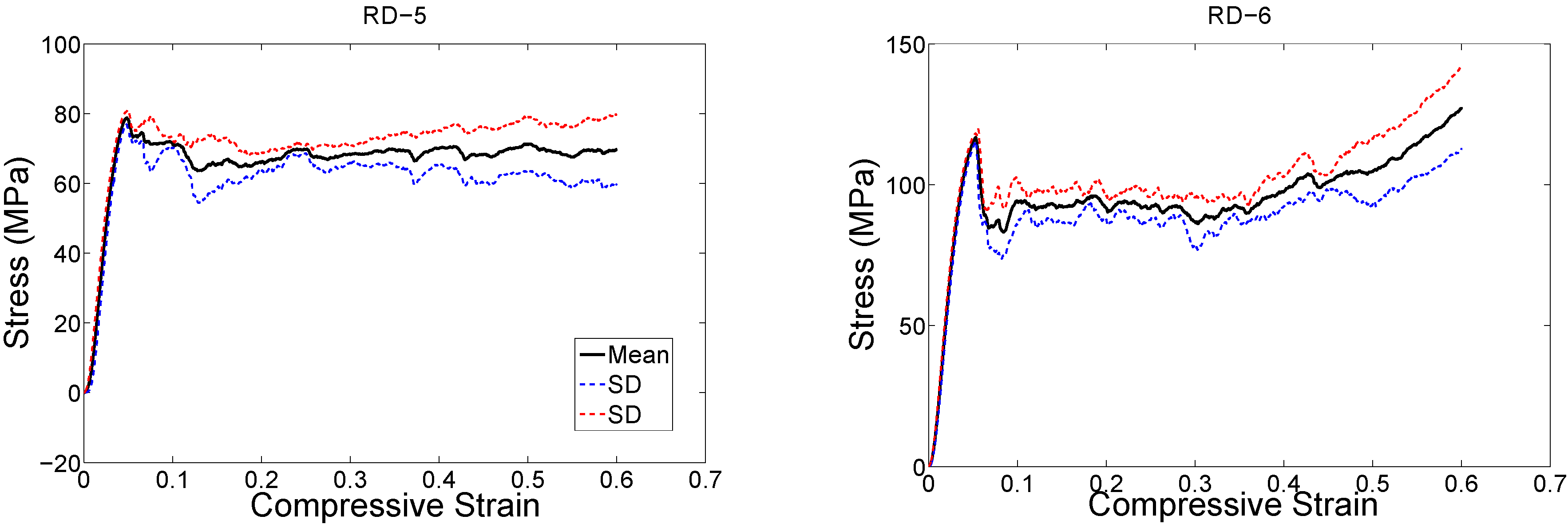
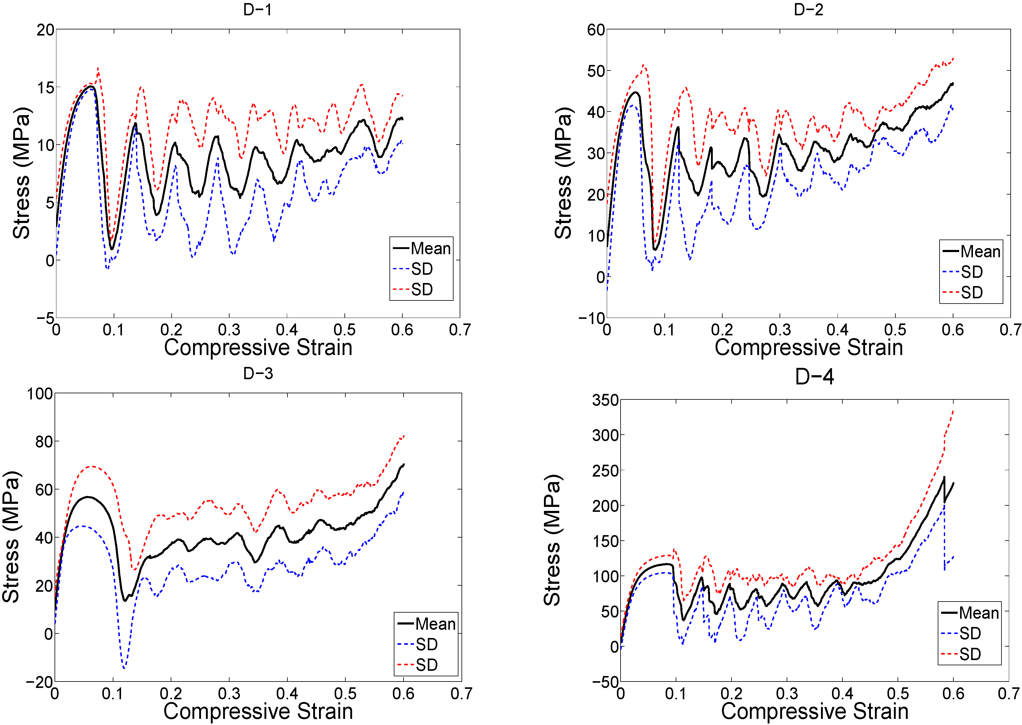
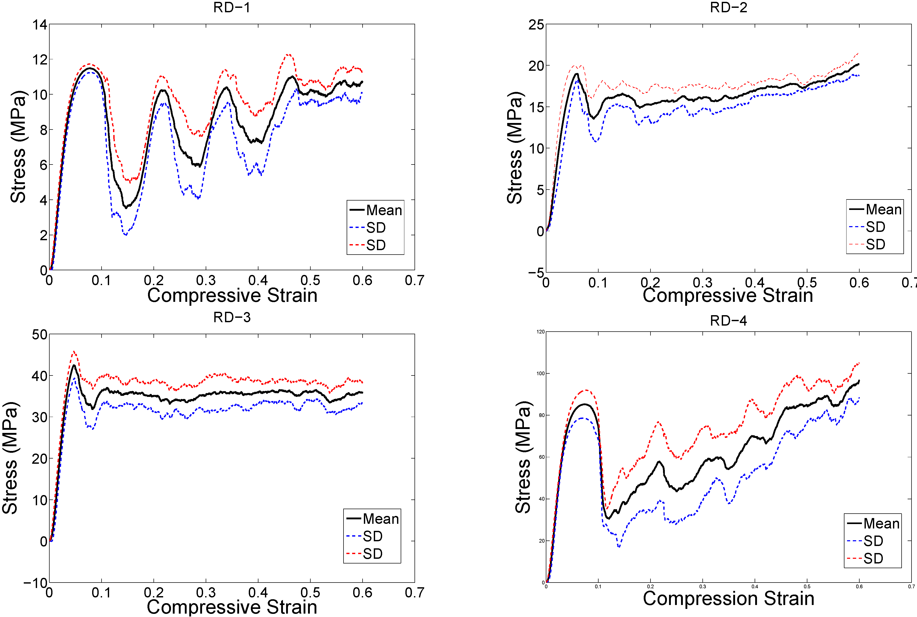
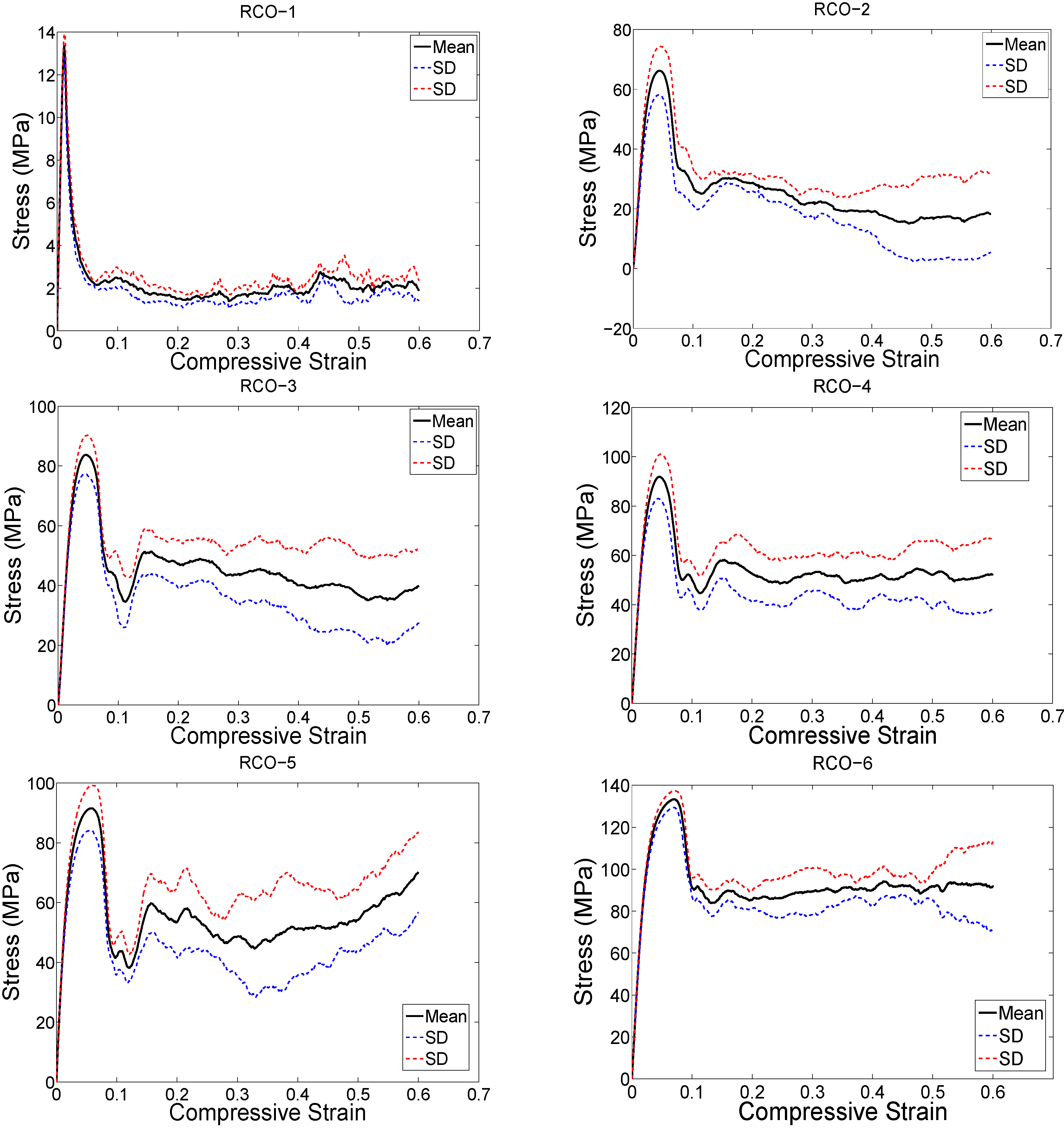
2.3. Compressive Testing
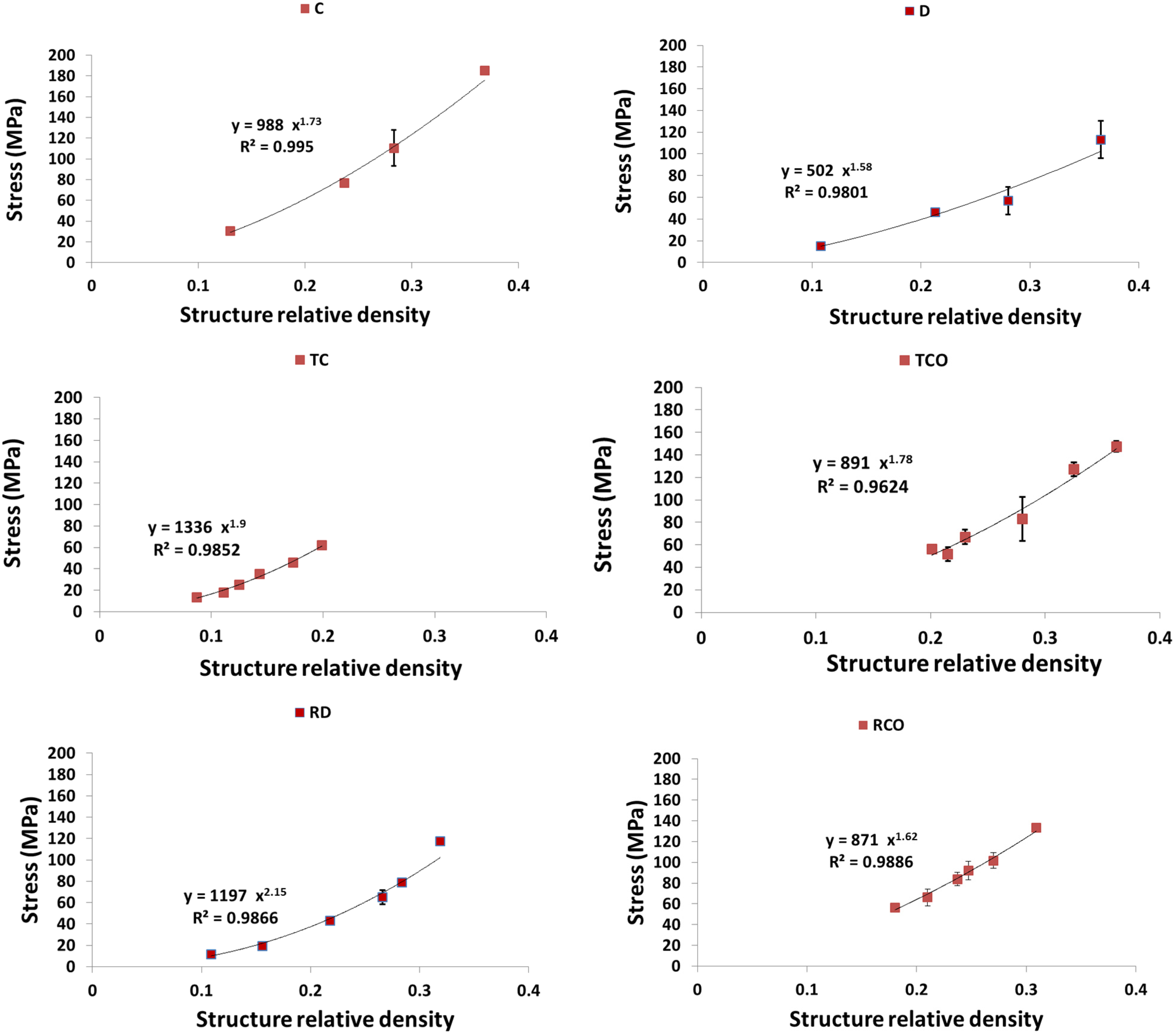
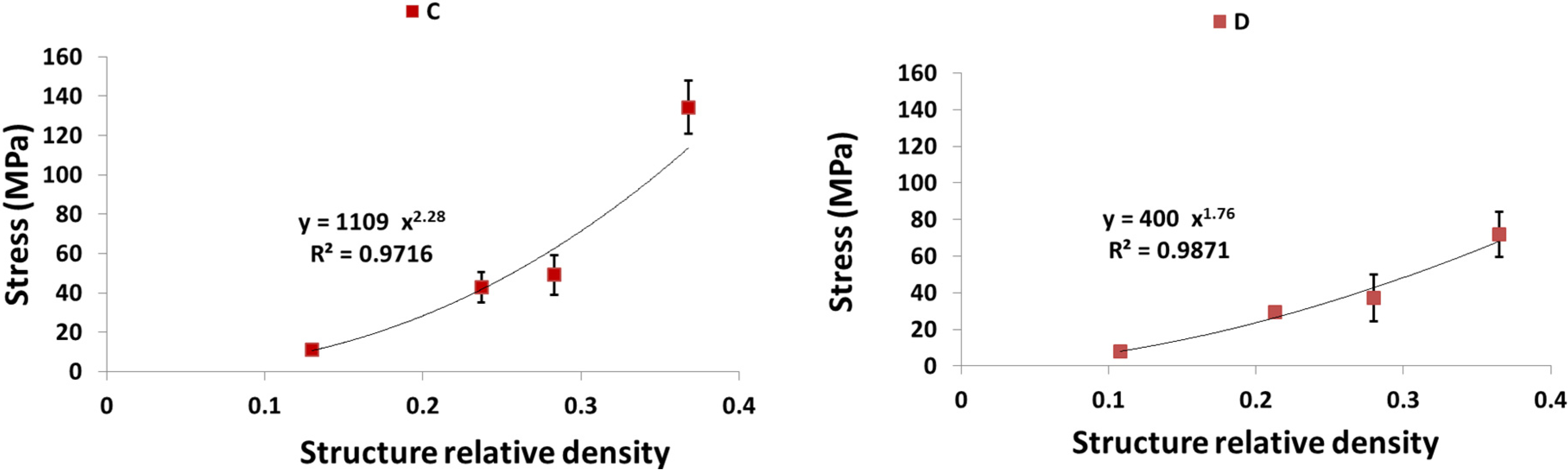
2.4. Correlational Analysis
3. Results
| Structure Relative Density (%) | ||||
|---|---|---|---|---|
| CAD File | Dry Weighing (SD) | Archimedes (SD) | μCT | |
| Cubic (C) | ||||
| C-1 | 10 | 11 (0.1) | 12 (0.1) | 13 |
| C-2 | 22 | 21 (0.2) | 22 (0.2) | 24 |
| C-3 | 27 | 26 (0.2) | 26 (0.2) | 28 |
| C-4 | 35 | 34 (0.1) | 34 (0.2) | 37 |
| Diamond (D) | ||||
| D-1 | 11 | 11 (0.1) | 11 (0.2) | 11 |
| D-2 | 21 | 20 (0.2) | 21 (0.1) | 21 |
| D-3 | 28 | 26 (0.4) | 27 (0.3) | 28 |
| D-4 | 37 | 34 (0.3) | 35 (0.4) | 36 |
| Truncated cube (TC) | ||||
| TC-1 | 6 | 7 (0.1) | 7(0.1) | 9 |
| TC-2 | 9 | 9 (0.1) | 9 (0.1) | 11 |
| TC-3 | 12 | 12 (0.1) | 12 (0.1) | 12 |
| TC-4 | 16 | 14 (0.2) | 15 (0.2) | 14 |
| TC-5 | 21 | 17 (0.2) | 18 (0.1) | 17 |
| TC-6 | 24 | 20 (0.2) | 20 (0.2) | 20 |
| Truncated Cubeoctahedron (TCO) | ||||
| TCO-1 | 18 | 20 (0.4) | 20 (0.4) | 19 |
| TCO-2 | 21 | 23 (0.2) | 23 (0.2) | 21 |
| TCO-3 | 26 | 25 (0.5) | 25 (0.5) | 23 |
| TCO-4 | 31 | 28 (0.2) | 28 (0.3) | 28 |
| TCO-5 | 34 | 31 (0.3) | 31 (0.3) | 32 |
| TCO-6 | 36 | 34 (0.2) | 35 (0.3) | 36 |
| Rhombicdodecahdron (RD) | ||||
| RD-1 | 10 | 11 (0.3) | 11 (0.4) | 11 |
| RD-2 | 15 | 17 (0.2) | 17 (0.1) | 16 |
| RD-3 | 20 | 23 (0.2) | 23 (0.1) | 22 |
| RD-4 | 25 | 27 (0.1) | 27 (0.2) | 27 |
| RD-5 | 29 | 28 (0.3) | 28 (0.3) | 28 |
| RD-6 | 34 | 33 (0.3) | 33 (0.2) | 32 |
| Rhombic Cubeoctahedron (RCO) | ||||
| RCO-1 | 16 | 18 (0.2) | 18 (0.2) | 18 |
| RCO-2 | 18 | 21 (0.2) | 21 (0.2) | 21 |
| RCO-3 | 21 | 23 (0.3) | 23 (0.3) | 24 |
| RCO-4 | 26 | 25 (0.3) | 26 (0.4) | 25 |
| RCO-5 | 31 | 29 (0.4) | 29 (0.4) | 27 |
| RCO-6 | 36 | 32 (0.3) | 33 (0.5) | 31 |


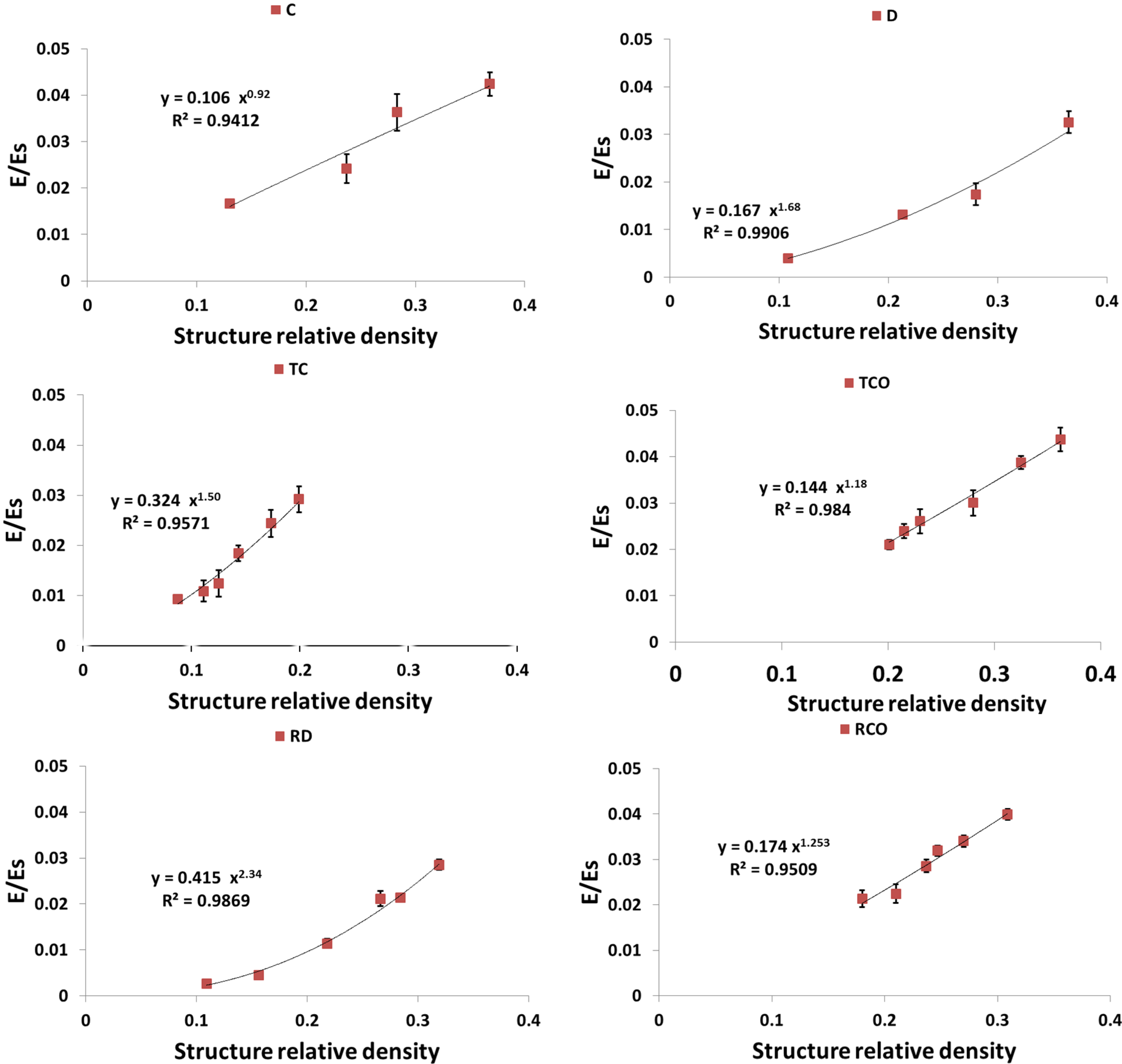


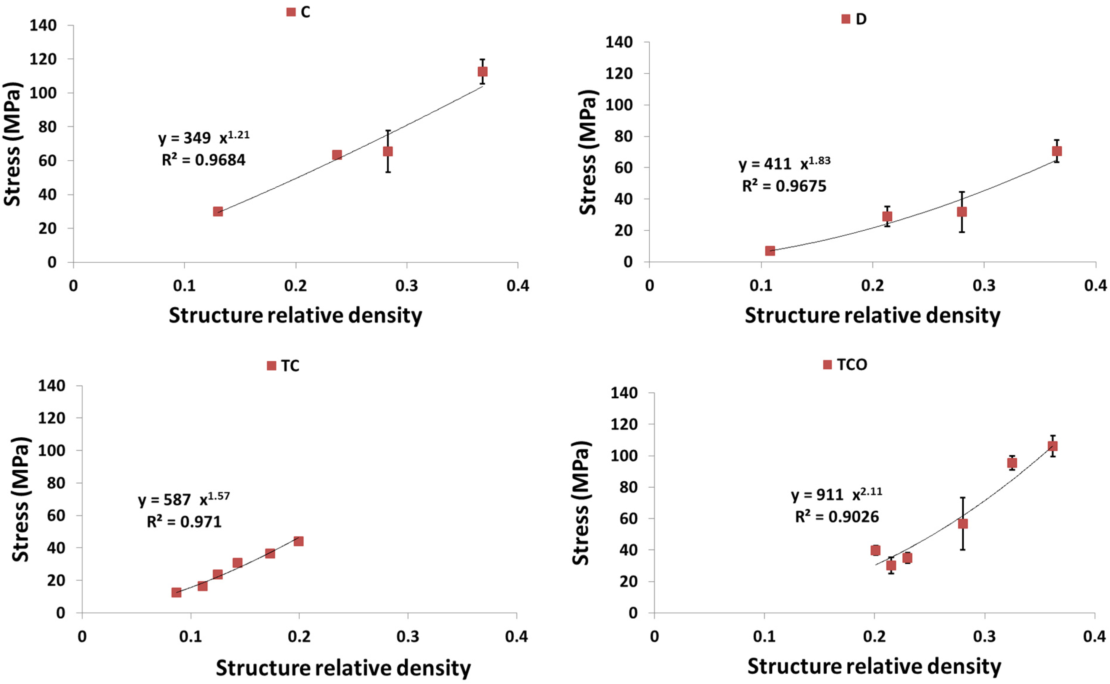
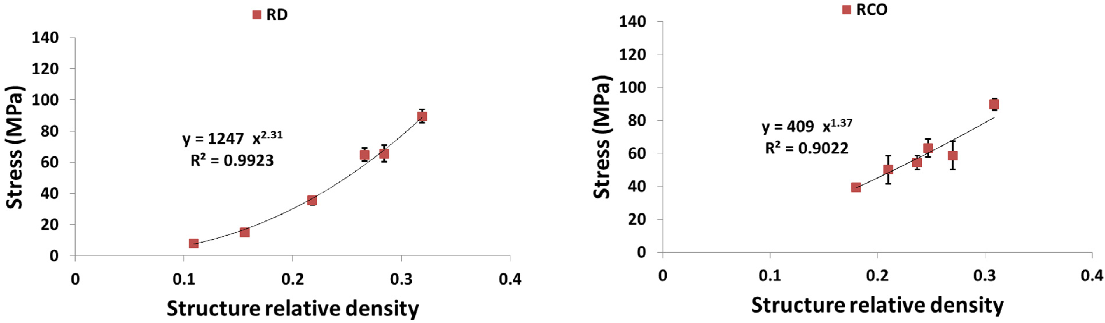


4. Discussion
4.1. Comparison between the Different Types of Unit Cells
4.2. Ratio of Plateau Stress to Yield Stress
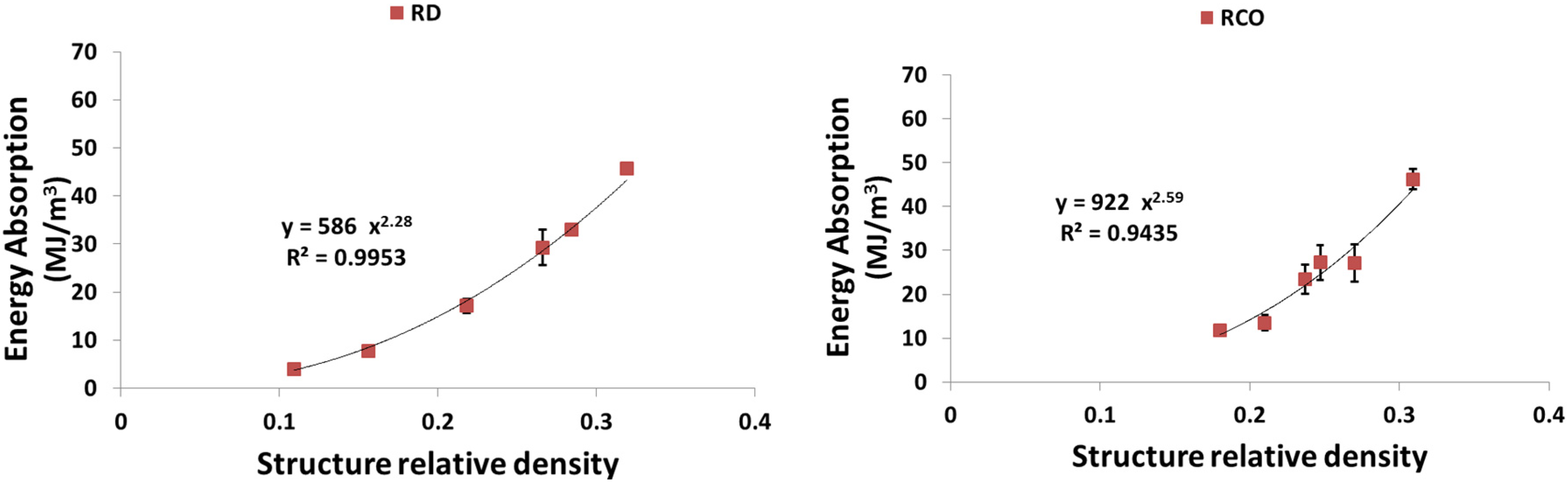
4.3. Energy Absorption
4.4. Anisotropy
4.5. Applications in the Design of Implants and Tissue Engineering Scaffolds
4.6. Future Research
5. Conclusions
Author Contributions
Conflicts of Interest
References
- Butscher, A.; Bohner, M.; Holmann, S.; Gauckler, L.; Muller, R. Structural and material approaches for bone tissue engineering in powder based 3D printing. Acta Biomater. 2013, 7, 907–920. [Google Scholar]
- Hollister, S.J. Porous scaffold design for tissue engineering. Nat. Mater. 2005, 4, 518–524. [Google Scholar]
- Hollister, S.J. Scaffold design and manufacturing: From concept to clinic. Adv. Mater. 2009, 21, 3330–3342. [Google Scholar]
- Hutmacher, D.W. Scaffold design and fabrication technologies for engineering tissues—State of the art and future perspectives. J. Biomater. Sci. Polym. Ed. 2001, 12, 107–124. [Google Scholar]
- Cook, S.; Dalton, J. Biocompatibility and biofunctionality of implanted materials. Alpha Omegan 1991, 85, 41–47. [Google Scholar]
- Gotman, I. Characteristics of metals used in implants. J. Endourol. 1997, 11, 383–389. [Google Scholar]
- Goulet, R.W.; Goldstein, S.A.; Ciarelli, M.J.; Kuhn, J.L.; Brown, M.B.; Feldkamp, L.A. The relationship between the structural and orthogonal compressive properties of trabecular bone. J. Biomech. 1994, 27, 375–377. [Google Scholar]
- Dias, M.R.; Guedes, J.M.; Flanagan, C.L.; Hollister, S.J.; Fernandes, P.R. Optimization of scaffold design for bone tissue engineering: A computational and experimental study. Med. Eng. Phys. 2014, 36, 448–457. [Google Scholar]
- Dias, M.R.; Fernandes, P.R.; Guedes, J.M.; Hollister, S.J. Permeability analysis of scaffolds for bone tissue engineering. J. Biomech. 2012, 45, 938–944. [Google Scholar]
- Ahmadi, S.M.; Campoli, G.; Yavari, S.A.; Sajadi, B.; Wauthle, R.; Schrooten, J.; Weinans, H.; Zadpoor, A.A. Mechanical behavior of regular open-cell porous biomaterials made of diamond lattice unit cells. J. Mech. Behav. Biomed. Mater. 2014, 34, 106–115. [Google Scholar]
- Niinomi, M. Mechanical properties of biomedical titanium alloys. Mater. Sci. Eng.: A 1998, 243, 231–236. [Google Scholar]
- Engh, C.; Bobyn, J.; Glassman, A. Porous-coated hip replacement. The factors governing bone ingrowth, stress shielding, and clinical results. J. Bone Joint Surg. Br. 1987, 69, 45–55. [Google Scholar]
- Engh, C.A., Jr.; Young, A.M.; Engh, C.A.; Robert, H., Jr. Clinical consequences of stress shielding after porous-coated total hip arthroplasty. Clin. Orthop. Relat. Res. 2003, 417, 157–163. [Google Scholar]
- Huiskes, R.; Weinans, H.; van Rietbergen, B. The relationship between stress shielding and bone resorption around total hip stems and the effects of flexible materials. Clin. Orthop. Relat. Res. 1992, 274, 124–134. [Google Scholar]
- Nagels, J.; Stokdijk, M.; Rozing, P.M. Stress shielding and bone resorption in shoulder arthroplasty. J. Shoulder Elbow Surg. 2003, 12, 35–39. [Google Scholar]
- Amin Yavari, S.; Ahmadi, S.M.; van der Stok, J.; Wauthle, R.; Riemslag, A.C.; Janssen, M.; Schrooten, J.; Weinans, H.; Zadpoor, A.A. Effects of bio-functionalizing surface treatments on the mechanical behavior of open porous titanium biomaterials. J. Mech. Behav. Biomed. Mater. 2014, 36, 109–119. [Google Scholar]
- Van der Stok, J.; van der Jagt, O.P.; Yavari, S.A.; de Haas, M.F.P.; Waarsing, J.H.; Jahr, H.; van Lieshout, E.M.M.; Patka, P.; Verhaar, J.A.N.; Zadpoor, A.A.; et al. Selective laser melting-produced porous titanium scaffolds regenerate bone in critical size cortical bone defects. J. Orthop. Res. 2013, 31, 792–799. [Google Scholar]
- Imwinkelried, T. Mechanical properties of open-pore titanium foam. J. Biomed. Mater. Res. Part A 2007, 81, 964–970. [Google Scholar]
- Krishna, B.V.; Bose, S.; Bandyopadhyay, A. Low stiffness porous Ti structures for load-bearing implants. Acta Biomater. 2007, 3, 997–1006. [Google Scholar]
- Torres, Y.; Pavón, J.J.; Rodríguez, J.A. Processing and characterization of porous titanium for implants by using NaCl as space holder. J. Mater. Process. Technol. 2012, 212, 1061–1069. [Google Scholar]
- Yang, D.; Shao, H.; Guo, Z.; Lin, T.; Fan, L. Preparation and properties of biomedical porous titanium alloys by gelcasting. Biomed. Mater. 2011, 6. [Google Scholar] [CrossRef]
- Bartolo, P.; Kruth, J.-P.; Silva, J.; Levy, G.; Malshe, A.; Rajurkar, K.; Mitsuishi, M.; Ciurana, J.; Leu, M. Biomedical production of implants by additive electro-chemical and physical processes. CIRP Ann. Manuf. Technol. 2012, 61, 635–655. [Google Scholar]
- Gu, D.; Meiners, W.; Wissenbach, K.; Poprawe, R. Laser additive manufacturing of metallic components: Materials, processes and mechanisms. Int. Mater. Rev. 2012, 57, 133–164. [Google Scholar]
- Mironov, V.; Trusk, T.; Kasyanov, V.; Little, S.; Swaja, R.; Markwald, R. Biofabrication: A 21st century manufacturing paradigm. Biofabrication 2009, 1. [Google Scholar] [CrossRef]
- Murr, L.; Gaytan, S.M.; Medina, F.; Lopez, H.; Martinez, E.; Machado, B.I.; Hernandez, D.H.; Martinez, L.; Lopez, M.I.; Wicker, R.B.; et al. Next-generation biomedical implants using additive manufacturing of complex, cellular and functional mesh arrays. Philos. Trans. R. Soc. A: Math. Phys. Eng. Sci. 2010, 368, 1999–2032. [Google Scholar]
- Louvis, E.; Fox, P.; Sutcliffe, C.J. Selective laser melting of aluminium components. J. Mater. Process. Technol. 2011, 211, 275–284. [Google Scholar]
- Mullen, L.; Stamp, R.C.; Brooks, W.K.; Jones, E.; Sutcliffe, C.J. Selective Laser Melting: A regular unit cell approach for the manufacture of porous, titanium, bone in-growth constructs, suitable for orthopedic applications. J. Biomed. Mater. Res. Part B: Appl. Biomater. 2009, 89, 325–334. [Google Scholar]
- Mullen, L.; Stamp, R.C.; Fox, P.; Jones, E.; Ngo, C.; Sutcliffe, C.J. Selective laser melting: A unit cell approach for the manufacture of porous, titanium, bone in-growth constructs, suitable for orthopedic applications. II. Randomized structures. J. Biomed. Mater. Res. Part B: Appl. Biomater. 2010, 92, 178–188. [Google Scholar]
- Vandenbroucke, B.; Kruth, J. Selective laser melting of biocompatible metals for rapid manufacturing of medical parts. Rapid Prototyp. J. 2007, 13, 196–203. [Google Scholar]
- Attar, H.; Calin, M.; Zhang, L.C.; Scudino, S.; Eckert, J. Manufacture by selective laser melting and mechanical behavior of commercially pure titanium. Mater. Sci. Eng.: A 2014, 593, 170–177. [Google Scholar]
- Heinl, P.; Müller, L.; Körner, C.; Singer, R.F.; Müller, F.A. Cellular Ti–6Al–4V structures with interconnected macro porosity for bone implants fabricated by selective electron beam melting. Acta Biomater. 2008, 4, 1536–1544. [Google Scholar]
- Li, X.; Wang, C.; Zhang, W.; Li, Y. Fabrication and characterization of porous Ti6Al4V parts for biomedical applications using electron beam melting process. Mater. Lett. 2009, 63, 403–405. [Google Scholar]
- Parthasarathy, J.; Starly, B.; Raman, S.; Christensen, A. Mechanical evaluation of porous titanium (Ti6Al4V) structures with electron beam melting (EBM). J. Mech. Behav. Biomed. Mater. 2010, 3, 249–259. [Google Scholar]
- Ponader, S.; von Wilmowsky, C.; Widenmayer, M.; Lutz, R.; Heinl, P.; Körner, C.; Singer, R.F.; Nkenke, E.; Neukam, F.W.; Schlegel, K.A. In vivo performance of selective electron beam-melted Ti-6Al-4V structures. J. Biomed. Mater. Res. Part A 2010, 92, 56–62. [Google Scholar]
- Van der Stok, J.; Wang, H.; Amin, Y.S.; Siebelt, M.; Sandker, M.; Waarsing, J.H.; Verhaar, J.A.; Jahr, H.; Zadpoor, A.A.; Leeuwenburgh, S.C.; et al. Enhanced bone regeneration of cortical segmental bone defects using porous titanium scaffolds incorporated with colloidal gelatin gels for time-and dose-controlled delivery of dual growth factors. Tissue Eng. Part A 2013, 19, 2605–2614. [Google Scholar]
- Amin Yavari, S.; Wauthle, R.; Böttger, A.J.; Schrooten, J.; Weinans, H.; Zadpoor, A.A. Crystal structure and nanotopographical features on the surface of heat-treated and anodized porous titanium biomaterials produced using selective laser melting. Appl. Surf. Sci. 2014, 290, 287–294. [Google Scholar]
- Chen, X.-B.; Li, Y.C.; Du Plessis, J.; Hodgson, P.D.; Wen, C. Influence of calcium ion deposition on apatite-inducing ability of porous titanium for biomedical applications. Acta Biomater. 2009, 5, 1808–1820. [Google Scholar]
- Liang, F.; Zhou, L.; Wang, K. Apatite formation on porous titanium by alkali and heat-treatment. Surf. Coat. Technol. 2003, 165, 133–139. [Google Scholar]
- Lopez-Heredia, M.A.; Sohier, J.; Gaillard, C.; Quillard, S.; Dorget, M.; Layrolle, P. Rapid prototyped porous titanium coated with calcium phosphate as a scaffold for bone tissue engineering. Biomaterials 2008, 29, 2608–2615. [Google Scholar]
- Campoli, G.; Borleffs, M.S.; Amin Yavari, S.; Wauthle, R.; Weinans, H.; Zadpoor, A.A. Mechanical properties of open-cell metallic biomaterials manufactured using additive manufacturing. Mater. Des. 2013, 49, 957–965. [Google Scholar]
- Hazlehurst, K.B.; Wang, C.J.; Stanford, M. A numerical investigation into the influence of the properties of cobalt chrome cellular structures on the load transfer to the periprosthetic femur following total hip arthroplasty. Med. Eng. Phys. 2014, 36, 458–466. [Google Scholar]
- Lewis, G. Properties of open-cell porous metals and alloys for orthopaedic applications. J. Mater. Sci.: Mater. Med. 2013, 24, 2293–2325. [Google Scholar]
- Li, S.; Xu, Q.S.; Wang, Z.; Hou, W.T.; Hao, Y.L.; Yang, R.; Murr, L.E. Influence of cell shape on mechanical properties of Ti-6Al-4V meshes fabricated by electron beam melting method. Acta Biomater. 2014, 10, 4537–4547. [Google Scholar]
- Wauthle, R.; Vrancken, B.; Beynaerts, B.; Jorissen, K.; Schrooten, J.; Kruth, J.-P.; van Humbeeck, J. Effects of build orientation and heat treatment on the microstructure and mechanical properties of selective laser melted Ti6Al4V lattice structures. Addit. Manuf. 2015, 5, 77–84. [Google Scholar]
- Wieding, J.; Jonitz, A.; Bader, R. The effect of structural design on mechanical properties and cellular response of additive manufactured titanium scaffolds. Materials 2012, 5, 1336–1347. [Google Scholar]
- Wieding, J.; Wolf, A.; Bader, R. Numerical optimization of open-porous bone scaffold structures to match the elastic properties of human cortical bone. J. Mech. Behav. Biomed. Mater. 2014, 37, 56–68. [Google Scholar]
- Pyka, G.; Burakowski, A.; Kerckhofs, G.; Moesen, M.; van Bael, S.; Schrooten, J.; Wevers, M. Surface modification of Ti6Al4V open porous structures produced by additive manufacturing. Adv. Eng. Mater. 2012, 14, 363–370. [Google Scholar]
- Van Bael, S.; Kerckhofs, G.; Moesen, M.; Pyka, G.; Schrooten, J.; Krutha, J.P. Micro-CT-based improvement of geometrical and mechanical controllability of selective laser melted Ti6Al4V porous structures. Mater. Sci. Eng. A 2011, 528, 7423–7431. [Google Scholar]
- Doube, M.; Kłosowski, M.M.; Arganda-Carreras, I.; Cordelières, F.P.; Dougherty, R.P.; Jackson, J.S.; Schmid, B.; Hutchinson, J.R.; Shefelbine, S.J. BoneJ: Free and extensible bone image analysis in ImageJ. Bone 2010, 47, 1076–1079. [Google Scholar]
- Amin Yavari, S.; Ahmadi, S.M.; Wauthle, R.; Pouran, B.; Schrooten, J.; Weinans, H.; Zadpoor, A.A. Relationship between unit cell type and porosity and the fatigue behavior of selective laser melted meta-biomaterials. J. Mech. Behav. Biomed. Mater. 2015, 43, 91–100. [Google Scholar]
- International Organization for Standardization (ISO). Mechanical Testing of Metals—Ductility Testing—Compression Test for Porous and Cellular Metals; ISO: Genva, Switzerland, 2011; Volume ISO 13314:2011. [Google Scholar]
- Kim, H.W.; Knowles, J.C.; Kim, H.E. Hydroxyapatite porous scaffold engineered with biological polymer hybrid coating for antibiotic Vancomycin release. J. Mater. Sci.: Mater. Med. 2005, 16, 189–195. [Google Scholar]
- Kenesei, P.; Kádár, C.; Rajkovits, Z.; Lendvai, J. The influence of cell-size distribution on the plastic deformation in metal foams. Scripta Mater. 2004, 50, 295–300. [Google Scholar]
- Yeni, Y.N.; Brown, C.U.; Wang, Z.; Norman, T.L. The influence of bone morphology on fracture toughness of the human femur and tibia. Bone 1997, 21, 453–459. [Google Scholar]
- Garrison, J.G.; Gargac, J.A.; Niebur, G.L. Shear strength and toughness of trabecular bone are more sensitive to density than damage. J. Biomech. 2011, 44, 2747–2754. [Google Scholar]
- Keaveny, T.M.; Wachtel, E.F.; Guo, X.E.; Hayes, W.C. Mechanical behavior of damaged trabecular bone. J. Biomech. 1994, 27, 1309–1318. [Google Scholar]
- Moore, T.L.A.; Gibson, L.J. Fatigue Microdamage in Bovine, Trabecular Bone. J. Biomech. Eng. 2003, 125, 769–776. [Google Scholar]
- Black, D.M.; Cummings, S.R.; Karpf, D.B.; Cauley, J.A.; Thompson, D.E.; Nevitt, M.C.; Bauer, D.C.; Genant, H.K.; Haskell, W.L.; Marcus, R.; et al. Randomised trial of effect of alendronate on risk of fracture in women with existing vertebral fractures. Lancet 1996, 348, 1535–1541. [Google Scholar]
- Morgan, E.F.; Bouxsein, M. Biomechanics of bone and age-related fractures. In Principles of Bone Biology, 3rd ed.; Bilezikian, J.P., Raisz, L.G., Martin, J., Eds.; Elsevier: Amsterdam, The Netherlands, 2008; pp. 29–51. [Google Scholar]
- Adachi, T.; Osako, Y.; Tanaka, M.; Hojo, M.; Hollister, S.J. Framework for optimal design of porous scaffold microstructure by computational simulation of bone regeneration. Biomaterials 2006, 27, 3964–3972. [Google Scholar]
- Carter, D.R.; Beaupré, G.S.; Giori, N.J.; Helms, J.A. Mechanobiology of skeletal regeneration. Clin. Orthop. Relat. Res. 1998, 355, S41–S55. [Google Scholar]
- Petite, H.; Viateau, V.; Bensaïd, W.; Meunier, A.; de Pollak, C.; Bourguignon, M.; Oudina, K.; Sedel, L.; Guillemin, G. Tissue-engineered bone regeneration. Nat. Biotechnol. 2000, 18, 959–963. [Google Scholar]
- Zadpoor, A.A. Open forward and inverse problems in theoretical modeling of bone tissue adaptation. J. Mech. Behav. Biomed. Mater. 2013, 27, 249–261. [Google Scholar]
- Harrysson, O.L.; Hosni, Y.A.; Nayfeh, J.F. Custom-designed orthopedic implants evaluated using finite element analysis of patient-specific computed tomography data: femoral-component case study. BMC Musculoskelet. Disord. 2007, 8. [Google Scholar] [CrossRef]
- Poelert, S.; Valstar, E.; Weinans, H.; Zadpoor, A.A. Patient-specific finite element modeling of bones. Proc. Inst. Mech. Eng. Part H: J. Eng. Med. 2013, 227, 464–478. [Google Scholar]
- Schileo, E.; Taddei, F.; Malandrino, A.; Cristofolini, L.; Viceconti, M. Subject-specific finite element models can accurately predict strain levels in long bones. J. Biomech. 2007, 40, 2982–2989. [Google Scholar]
- Lomov, S.V.; Boissec, P.; Deluycker, E.; Morestin, F.; Vanclooster, K.; Vandepitte, D.; Verpoest, I.; Willems, A. Full-field strain measurements in textile deformability studies. Compos. Part A: Appl. Sci. Manuf. 2008, 39, 1232–1244. [Google Scholar]
- Pan, B.; Xie, H.; Guo, Z.; Hua, T. Full-field strain measurement using a two-dimensional Savitzky-Golay digital differentiator in digital image correlation. Opt. Eng. 2007, 46. [Google Scholar] [CrossRef]
- Schmidt, T.; Tyson, J.; Galanulis, K. Full-field dynamic displacement and strain measurement using advanced 3d image correlation photogrammetry: Part 1. Exp. Tech. 2003, 27, 47–50. [Google Scholar]
- Zadpoor, A.A.; Sinke, J.; Benedictus, R. Experimental and numerical study of machined aluminum tailor-made blanks. J. Mater. Process. Technol. 2008, 200, 288–299. [Google Scholar]
- Hild, F.; Roux, S. Digital image correlation: from displacement measurement to identification of elastic properties—A review. Strain 2006, 42, 69–80. [Google Scholar]
- McCormick, N.; Lord, J. Digital image correlation. Mater. Today 2010, 13, 52–54. [Google Scholar]
- Wattrisse, B.; Chrysochoos, A.; Muracciole, J.-M.; Némoz-Gaillard, M. Analysis of strain localization during tensile tests by digital image correlation. Exp. Mech. 2001, 41, 29–39. [Google Scholar]
- Zadpoor, A.A.; Sinke, J.; Benedictus, R. Elastoplastic deformation of dissimilar-alloy adhesively-bonded tailor-made blanks. Mater. Des. 2010, 31, 4611–4620. [Google Scholar]
- Thompson, M.; Schell, H.; Lienau, J.; Duda, G.N. Digital image correlation: A technique for determining local mechanical conditions within early bone callus. Med. Eng. Phys. 2007, 29, 820–823. [Google Scholar]
- Verhulp, E.; Rietbergen, B.V.; Huiskes, R. A three-dimensional digital image correlation technique for strain measurements in microstructures. J. Biomech. 2004, 37, 1313–1320. [Google Scholar]
- Zhang, D.; Arola, D.D. Applications of digital image correlation to biological tissues. J. Biomed. Opt. 2004, 9, 691–699. [Google Scholar]
© 2015 by the authors; licensee MDPI, Basel, Switzerland. This article is an open access article distributed under the terms and conditions of the Creative Commons Attribution license (http://creativecommons.org/licenses/by/4.0/).
Share and Cite
Ahmadi, S.M.; Yavari, S.A.; Wauthle, R.; Pouran, B.; Schrooten, J.; Weinans, H.; Zadpoor, A.A. Additively Manufactured Open-Cell Porous Biomaterials Made from Six Different Space-Filling Unit Cells: The Mechanical and Morphological Properties. Materials 2015, 8, 1871-1896. https://doi.org/10.3390/ma8041871
Ahmadi SM, Yavari SA, Wauthle R, Pouran B, Schrooten J, Weinans H, Zadpoor AA. Additively Manufactured Open-Cell Porous Biomaterials Made from Six Different Space-Filling Unit Cells: The Mechanical and Morphological Properties. Materials. 2015; 8(4):1871-1896. https://doi.org/10.3390/ma8041871
Chicago/Turabian StyleAhmadi, Seyed Mohammad, Saber Amin Yavari, Ruebn Wauthle, Behdad Pouran, Jan Schrooten, Harrie Weinans, and Amir A. Zadpoor. 2015. "Additively Manufactured Open-Cell Porous Biomaterials Made from Six Different Space-Filling Unit Cells: The Mechanical and Morphological Properties" Materials 8, no. 4: 1871-1896. https://doi.org/10.3390/ma8041871