3.1. Instruments and Tools
During the past few years several transport codes have been developed and applied for numerical studies of GDT-NS in parallel to the experimental research. The plasma physics calculations of the neutron source’s parameters have been performed by the
Integrated Transport Code System (ITCS) [
11]. The ITCS includes different numerical codes for plasma, particle transport, and neutron production. The main ITCS module is the three-dimensional (3D)
Monte Carlo Fast Ion Transport (MCFIT) code. It is based on the theory of binary Coulomb collisions and the equations of classical magnetohydrodynamics. In the main scheme of the MCFIT code, which is standard for the Monte Carlo method, statistically independent histories of fast particles are generated and their contributions are summed up into well-defined estimation values for each parameter of interest. After simulating
N particle histories, the final result for each parameter is calculated as an average with the statistical error determined by R.M.S. deviations. It is evident that the method converges as
N−1/2. The transport code allows one to calculate a large variety of parameters. The result of the calculations is a database of parameters in the form of a discrete distribution on a phase space mesh defined by the user via a sequence of time intervals. The main parameters are as follows: the energy content of fast ions, the trapped NBI power, the charge-exchange loss power, the power of deceleration by electrons, the spatial distribution of nuclear fusion reactions (D–D and D–T), the neutron flux to specified spatial regions (“detectors”), and the distribution functions of fast ions over energy and pitch angle.
Last year, the MCFIT code has been substantially upgraded (to MCFIT+) for adequate simulation of various versions of the GDT-NS. For example, to calculate the energy distribution function of fast ions escaping from the trap through the magnetic mirrors, the code was supplemented with a special block for analyzing the energies of fast particles falling into the loss cone and reaching the mirror section. As a result, the absolute values of the fast ion flux were obtained for given energy intervals at the edge of each (western and eastern) mirror [
12]. Also, the GDT-related physical phenomena (a vortex confinement, ambipolar plugging, magnetic field perturbation by high β,
etc.) were taken into account during the code modification. The experimental and theoretical basis of these phenomena was obtained in the GDT experimental facility at the Budker Institute. At present, the ITCS with the main MCFIT+ code most completely describes the transport of fast ions in axisymmetric mirror traps and fusion devices based on them.
Brief simulations of GDT and GDT-NS plasma parameters, as well as optimization research, were done by the one-dimensional plasma code DOL. The DOL code was developed at the Budker Institute for the fast calculation of main plasma parameter evaluation in the mirror trap [
13]. The DOL code is intended to calculate the dynamics of plasma processes in mirror traps with two-component plasma. In this code, the distribution function of fast ions is calculated by solving the bounce-averaged kinetic equation with allowance for variations in the fast-particle distribution function along the trap axis for the case of the time scale order
τci «
τ|| «
τd ~
τs ~ τex. Here,
τci is the time of cyclotron gyration;
τ|| is the bounce-oscillation period; and
τd,
τs, and
τex are the characteristic times of deceleration, scattering, and charge exchange of fast particles, respectively. Longitudinal losses of warm plasma are modeled using a superposition of confinement mechanisms in the limiting cases by analogy with [
14]. In particular, the possibility of plasma confinement in the gas-dynamic or weakly collisional case is taken into account and the effect of the ambipolar potential created by the population of fast particles is also allowed. In addition, the DOL code allows one to simulate the interaction of plasma with the neutral gas created as a result of hot atom injection. The correctness of the code operation is verified by comparing it with the data of GDT experiments and results of calculations by the MCFIT+ code.
3.2. Results of the Numerical Simulations
Table 1 presents a summary of simulation results for several projects of the mirror-based neutron source. The first column (a) shows achieved GDT experimental results for comparison with parameters of the projected devices. The GDT experimental parameters were also simulated by the numerical codes described above. Results of this simulation are in a good agreement with experimental data, which is the best proof of our numerical tools.
The second column (b) presents parameters of the GDT-U project—a next step of the GDT experiments. A substantial modernization of the GDT magnetic system for 0.5 T in midplane and up to 15 T in mirrors is planned. A new NBI system with four modules of hydrogen or deuterium beams, each with 2.4 MW power, 20 keV energy and 30 ms pulse duration, will be realized in the near future. The main goals of the update are the demonstration of the increasing mirror plasma parameters closed to moderate the GDT neutron source project and achieving steady-state confinement.
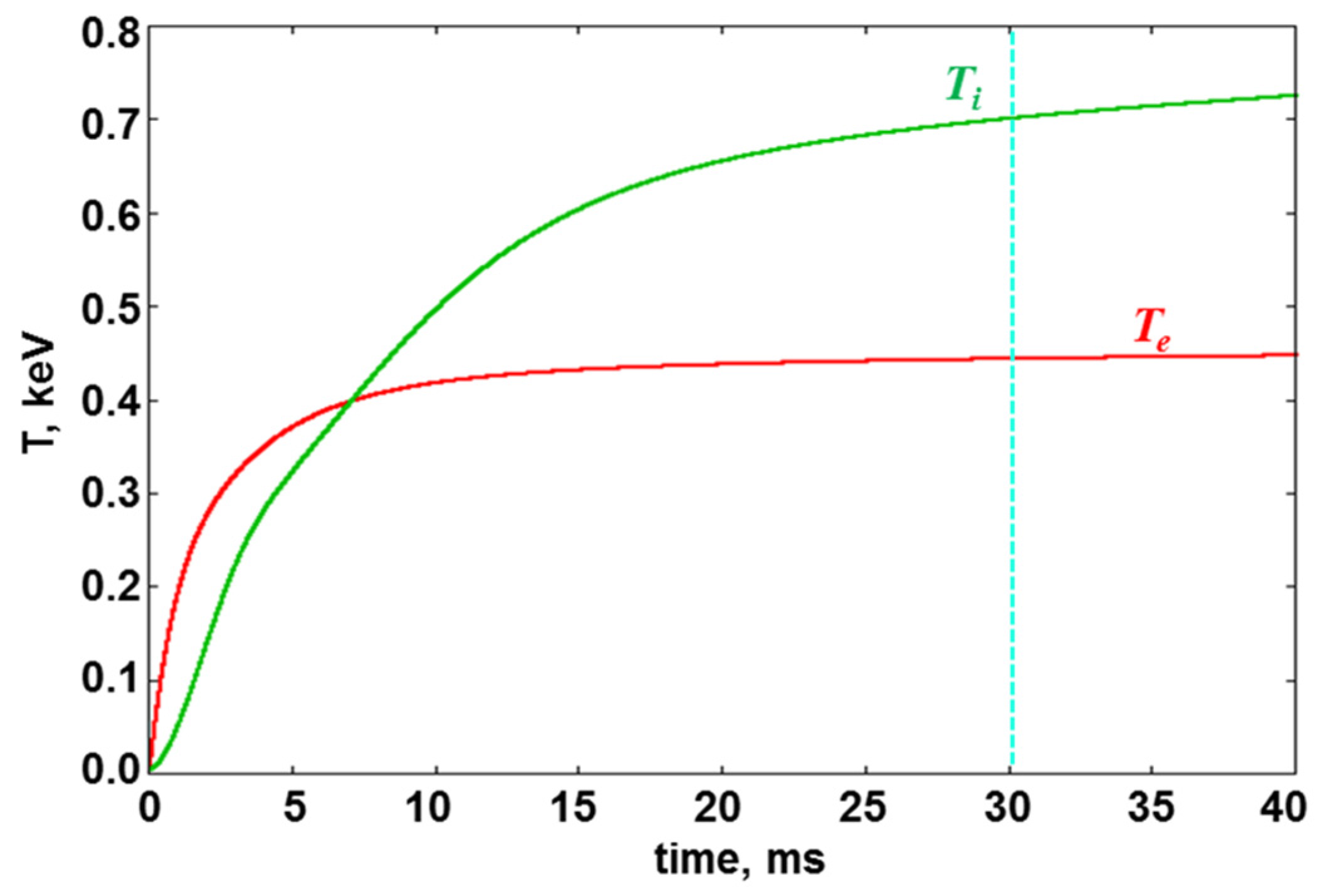
Figure 3 shows a projected time dependence of the ion (
Ti) and electron (
Te) temperatures in GDT-U during NBI heating only. It seems that the 30 ms power beam injection is sufficient for a physical steady-state regime. An additional ECRH can increase the electron temperature over 1 keV at parameters listed in
Table 1.
Table 1.
Main results of neutron source simulations. (a) Achieved GDT experimental results; (b) GDT-U project—a next step of the GDT experiments; (c) GDT-based neutron source (GDT-NS) proposed for fusion material research; (d) Gas-Dynamic Multiple-mirror Trap (GDMT); (e) Optimized mirror-based NS.
Table 1.
Main results of neutron source simulations. (a) Achieved GDT experimental results; (b) GDT-U project—a next step of the GDT experiments; (c) GDT-based neutron source (GDT-NS) proposed for fusion material research; (d) Gas-Dynamic Multiple-mirror Trap (GDMT); (e) Optimized mirror-based NS.
| Parameters | (a) | (b) | (c) | (d) | (e) |
|---|
| GDT exp. | GDT-U (next) | GDT-NS | GDMT-NS | Mirror NS |
|---|
| Magnetic field, B0/Bm (T) | 0.34/12 | 0.5/15 | 1/15 | 1/9 | 2/15 |
| Effective mirror ratio, k | 35 | 30 | 15 | 75 | 7.5 |
| Mirror-to-mirror distance, L (m) | 7 | 7 | 10 | 10 | 14 |
| NB injected/heat power, (MW) | 5/3 | 9.6/7.2 | 40/30 | 40/30 | 100/90 |
| NBI energy, Einj (keV) | 25 | 20 | 65 | 65 | 80 |
| Pulse duration, (s) | 0.005 | 0.03 | continuous | continuous | continuous |
| Warm ion density, nw (1020 m−3) | 0.3 | 0.5 | 0.2 | 0.3 | 0.08 |
| Fast ion density, nf (1020 m−3) | 0.5 | 0.7 | 2.5 | 3.5 | 2 |
| Mean ion energy, Ti (keV) | 10 | 10 | 35 | 30 | 60 |
| Electron temperature, Те (keV) | 0.25/0.9 * | 0.4/1* | 0.7 | 1.5 | 6 |
| Relative plasma pressure, β | 0.6 | 0.5 | 0.5 | 0.5 | 0.5 |
| Plasma radius, a (cm) | 14 | 10 | 8 | 8 | 20 |
| DT fusion energy gain factor, Qfus | – | – | 0.05 | 0.1 | 0.5 |
| DT fusion neutron power, Pn (MW) | – | – | 1.5 | 3 | 45 |
| Neutron flux density, qn (MW/m2) | – | – | 2 | 4 | 2 |
Figure 3.
Simulated electron (Te) and ion (Ti) temperatures in GDT-U vs. time after NBI is switched on.
Figure 3.
Simulated electron (Te) and ion (Ti) temperatures in GDT-U vs. time after NBI is switched on.
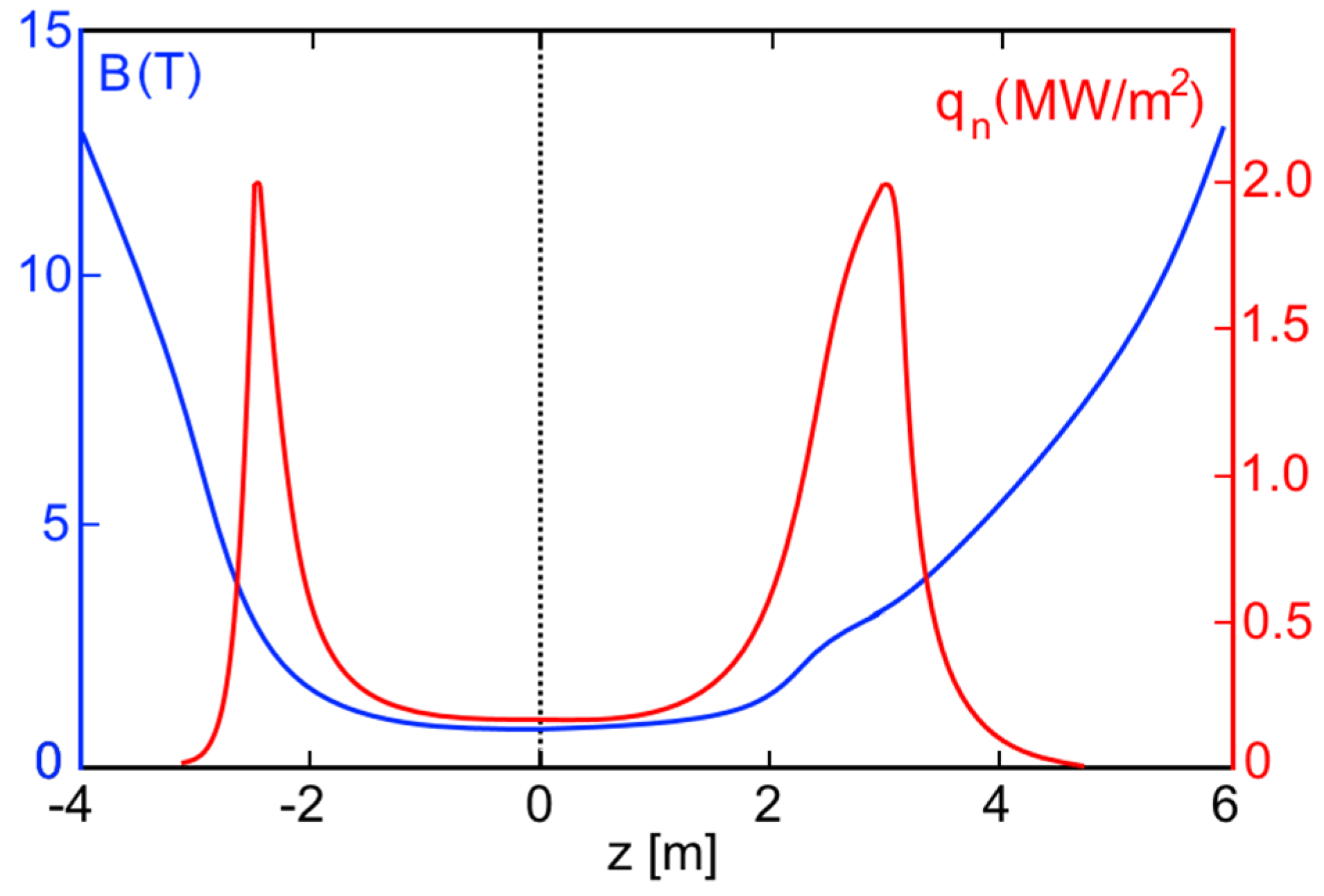
Several DT fusion neutron source projects were simulated on the basis of the achieved GDT experimental results (
Te ~ 1 keV, β ~ 0.5). The first of them is the GDT-NS, which is proposed for fusion material research [
2]. It is a 10--long axially symmetric mirror machine of the GDT type, with a magnetic field of
B0 = 1 T and a mirror ratio of 15. Similar to the GDT, the oblique injection of fast deuterium and tritium atoms into warm plasma produces a population of anisotropic fast deuterium–tritium (D–T) ions, which oscillate back and forth between the turning points near the end mirrors. As calculations show, there should be intensive radiation of 14 MeV neutrons in the vicinity of these turning points where the fast ion density has strong peaks. The source parameters are presented in column (c) of
Table 1. The total power of fusion neutron production in this source is 1.5 MW which corresponds to a neutron flux density of about 2 MW/m
2 in two effective testing areas of the order of 1 m
2. It is important to note that quite a moderate energy of neutral beam injection is used in this version (65 keV). Magnetic field and neutron flux density profiles along the axis of the system are shown in
Figure 4. The broadening of the right maximum of the flux density is determined by an appropriate tailoring of the magnetic field profile. A detailed description of the GDT-NS project, including SC coils, neutron shielding, test-zone design and other issues, is presented in [
2].
Figure 4.
Magnetic field profile (blue, left scale) and neutron flux density profile (red, right scale) in GDT-NS.
Figure 4.
Magnetic field profile (blue, left scale) and neutron flux density profile (red, right scale) in GDT-NS.
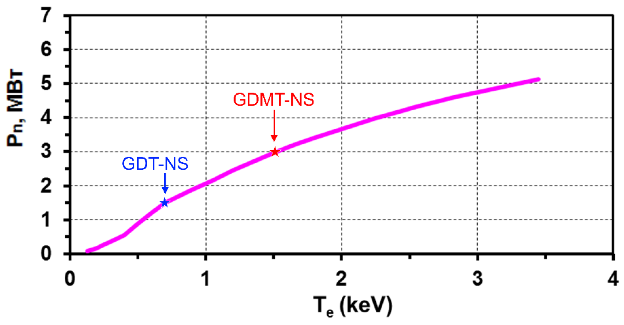
The electron temperature
Te is a very important parameter for a plasma neutron source. The energy confinement time of fast ions in GDT-based mirrors (which is determined basically by the electron dragging), and hence the fusion neutron production in GDT-NS, is strongly dependent on
Te.
Figure 5 demonstrates the important role of the electron temperature and presents a rise of the fusion neutron power
vs. Te in the GDT-based neutron source with a 40 MW 65 keV neutral beam injection (see column (c) and (d) of
Table 1). One can see that even greater than 4 MW neutron power can be achieved in GDT-NS with moderate injection energy of a D-T mixture if the electron temperature will be higher than 10
−2 Einj and reaches the value of 2–3 keV.
Figure 5.
Fusion neutron power vs. electron temperature for the GDT-based neutron source with 40 MW 65 keV neutral beam injection. Stars correspond to GDT-NS and GDMT-NS parameters.
Figure 5.
Fusion neutron power vs. electron temperature for the GDT-based neutron source with 40 MW 65 keV neutral beam injection. Stars correspond to GDT-NS and GDMT-NS parameters.
The Gas-Dynamic Multiple-mirror Trap (GDMT) [
15] combines the features of existing GOL-3 [
16] and GDT devices, namely the GDT-like central cell with sloshing ions produced by intense neutral beam injection, and the multiple-mirror end sections to suppress axial plasma losses. Such a combination became feasible due to recent findings in both GOL-3 and GDT experiments. The GDMT-based neutron source has an improved axial confinement with the effective mirror ratio
k = km∙χ up to 100, where
km =
Bm/B0 is the magnetic mirror ratio,
Bm,
B0 are magnetic field values in the mirror and central cell, and χ is a multiplication factor related to multiple-mirror confinement. The simulated GDT-NS parameters (see column (d) in
Table 1) allow us to propose this neutron source as a basis for different applications including a fusion material test facility with up to 4 MW/m
2 neutron flux density (see
Figure 5) and moderate fusion-driven (hybrid) systems (FDS).
The first analysis of possibility to use the GDT-based neutron source as a driver in the sub-critical system (FDS) was made in [
4], and the necessity of optimizing the GDT-NS parameters was shown. Optimized mirror-based NS with
Qfus = 0.5 uses 100 MW of 80 keV NBIs and has a 6-m-long neutron zone (n-zone) with a production up to 1.4 × 10
19 n/s. It assumes a kinetic regime of axial confinement, vortex transverse confinement, and warm maxwellian plasma minority for the DCLC stabilization. Main parameters of optimized Mirror NS are presented in column (e) of
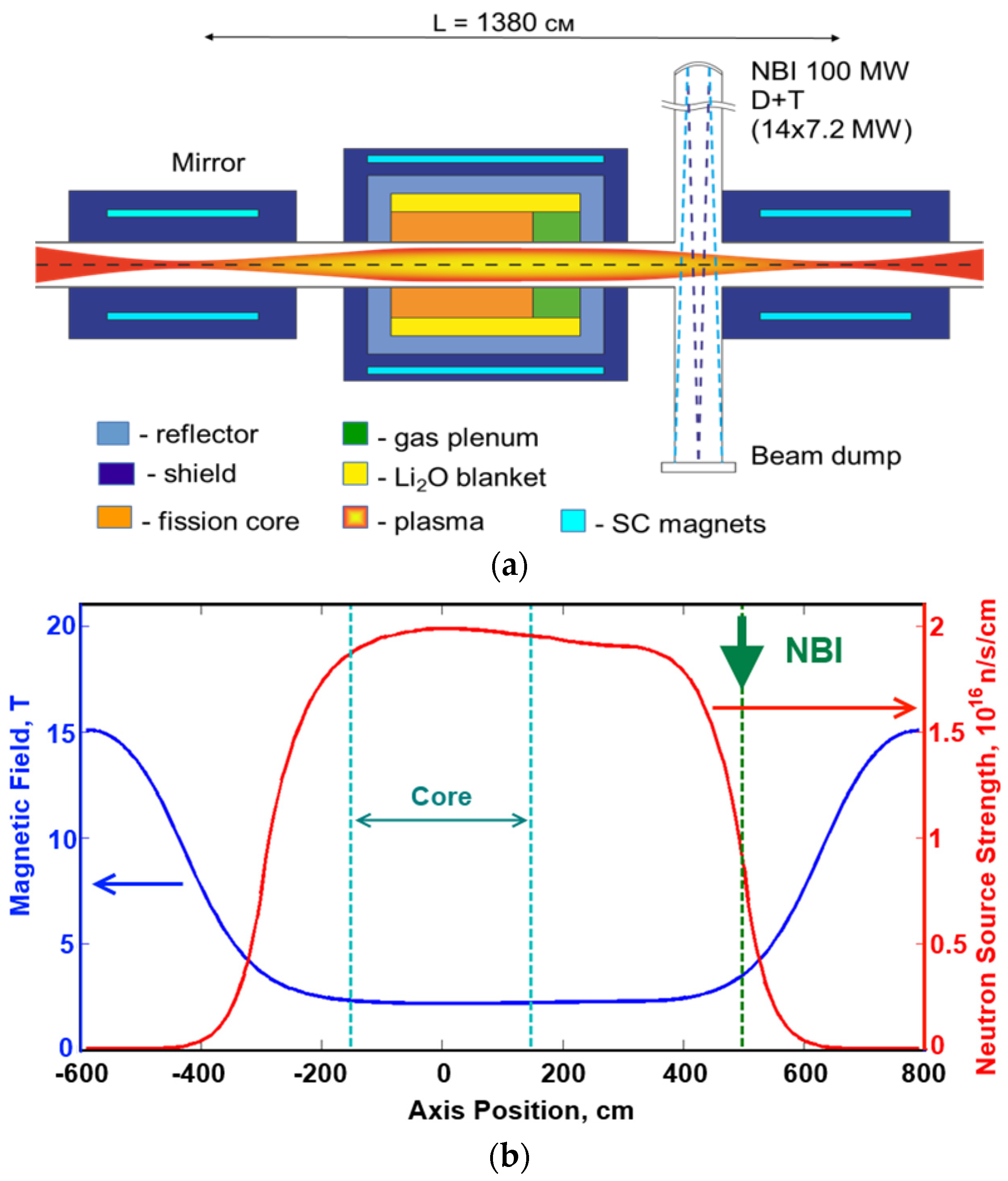
Table 1. This powerful NS is proposed as a basis of future FDS (hybrids) for MA burning or other nuclear energy applications. An approximate layout of the mirror-based FDS for minor actinide (MA) incineration is presented in
Figure 6a. The fusion source is assumed to be used with a sub-critical fission MA core and a Li
2O-filled tritium breeding blanket. The magnetic field strength and neutron emission yield (as numbers of neutrons per second per axial length unit) along the NS axis are shown in
Figure 6b. The neutron flux density on the first plasma wall was limited by the value of 2 MW/m
2, so the plasma wall radius is 30 cm. Further reduction of the first wall load is possible by increasing of the first wall radius. This is simply achieved in an axially symmetric chamber design.
Figure 6.
(a) Schematic view of FDS with mirror NS; (b) Magnetic field strength (left scale) and neutron emission yield (right scale) along the NS axis. Vertical dashed lines indicate the sub-critical core and the neutral beam injector positions.
Figure 6.
(a) Schematic view of FDS with mirror NS; (b) Magnetic field strength (left scale) and neutron emission yield (right scale) along the NS axis. Vertical dashed lines indicate the sub-critical core and the neutral beam injector positions.


