
Bismuth Sodium Titanate Based Materials for Piezoelectric Actuators


Abstract
:1. Introduction
2. Structure of BNT and Its Solid Solutions
2.1. Room Temperature Structure

2.2. High Temperature Phase Transitions

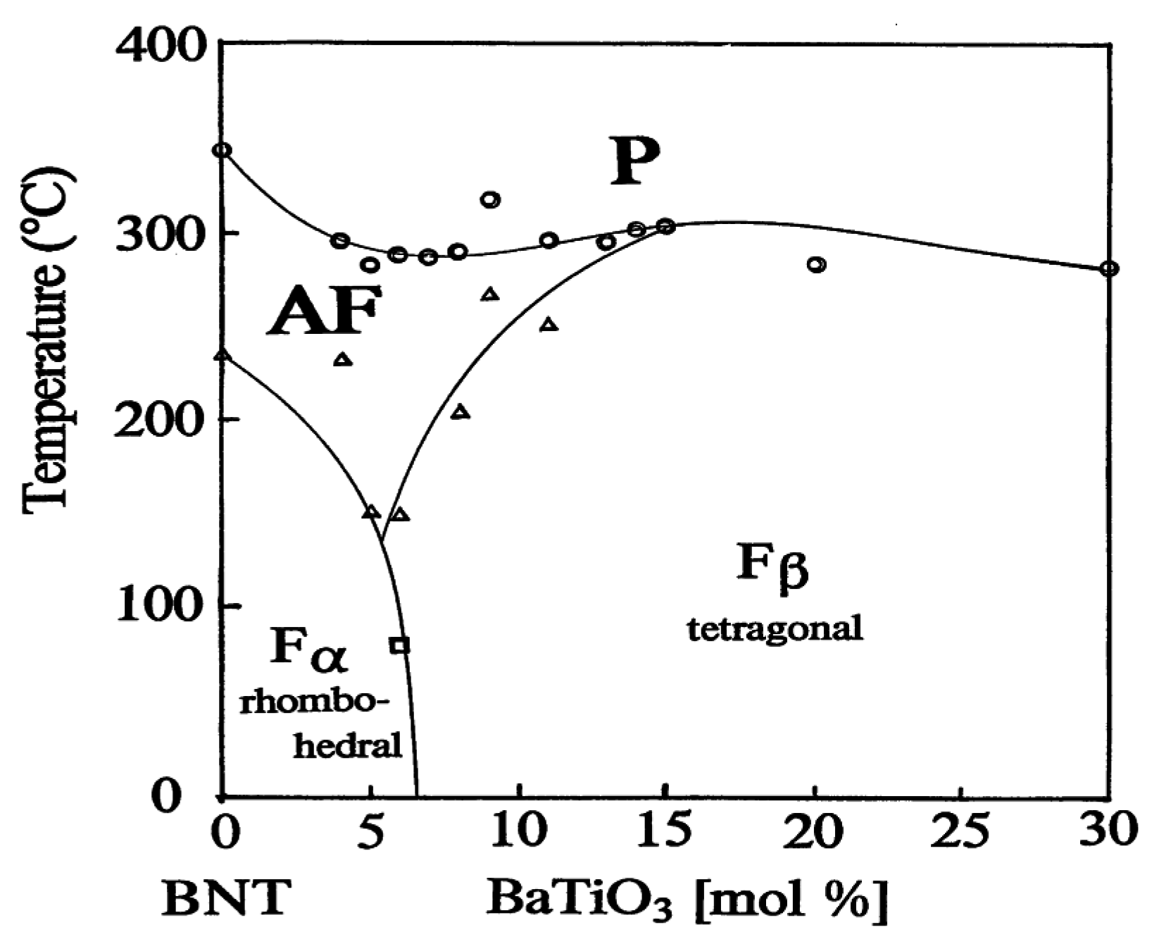
2.3. Phase Diagrams of Solid Solutions
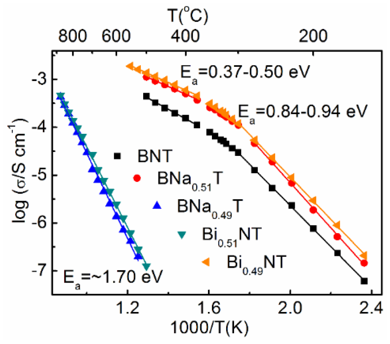
2.4. Nonstoichiometry and Defect Chemistry

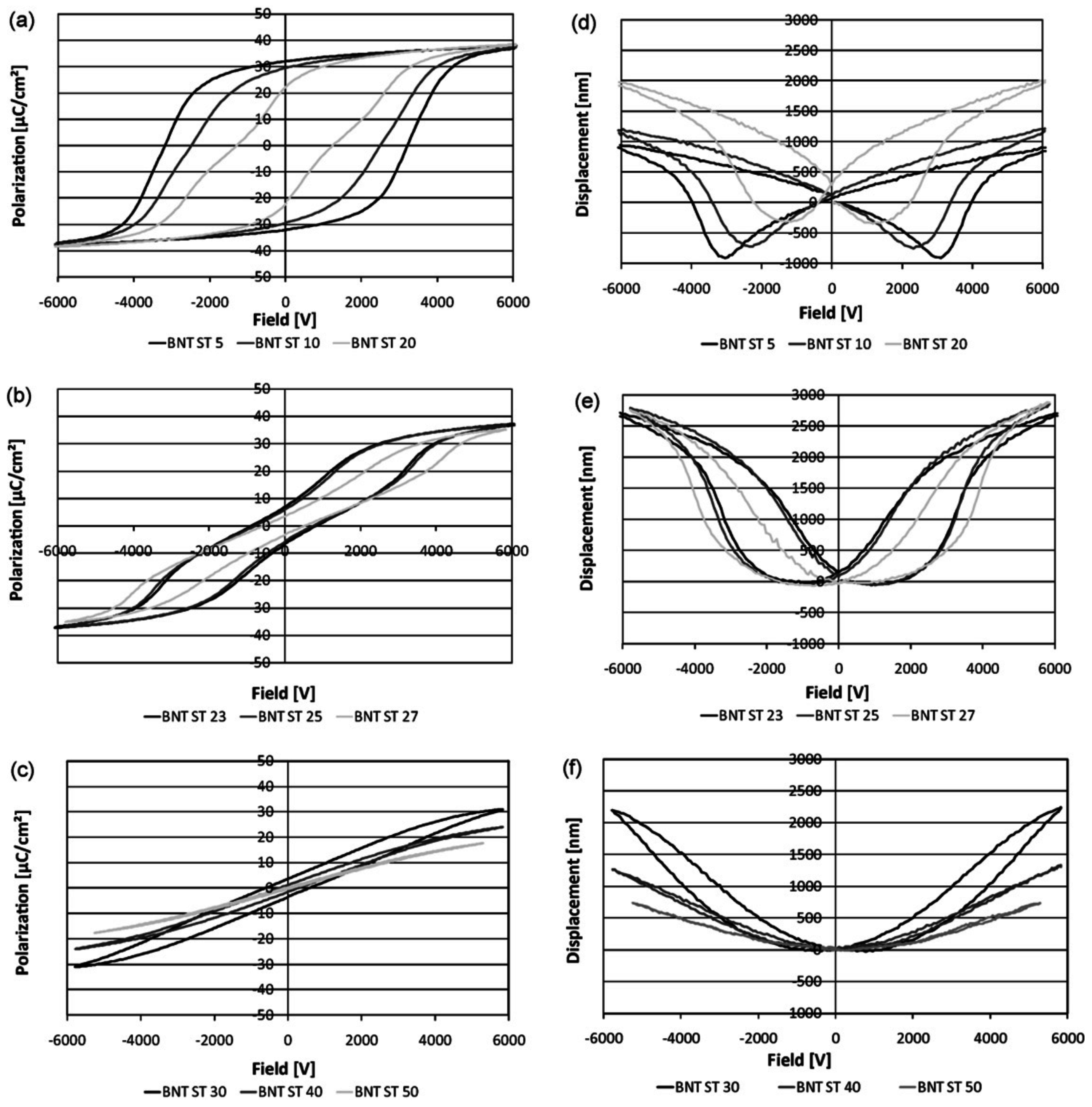
3. Polarization and Strain Curves


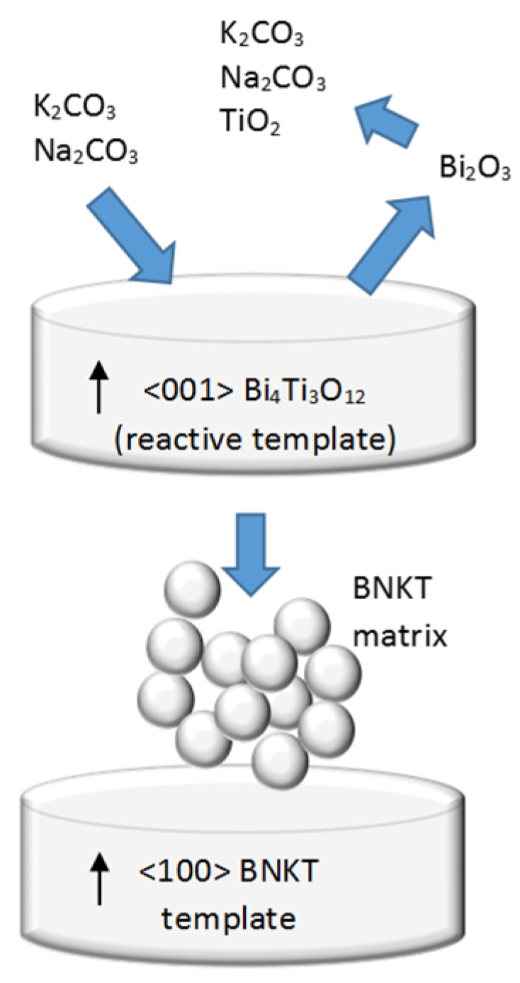
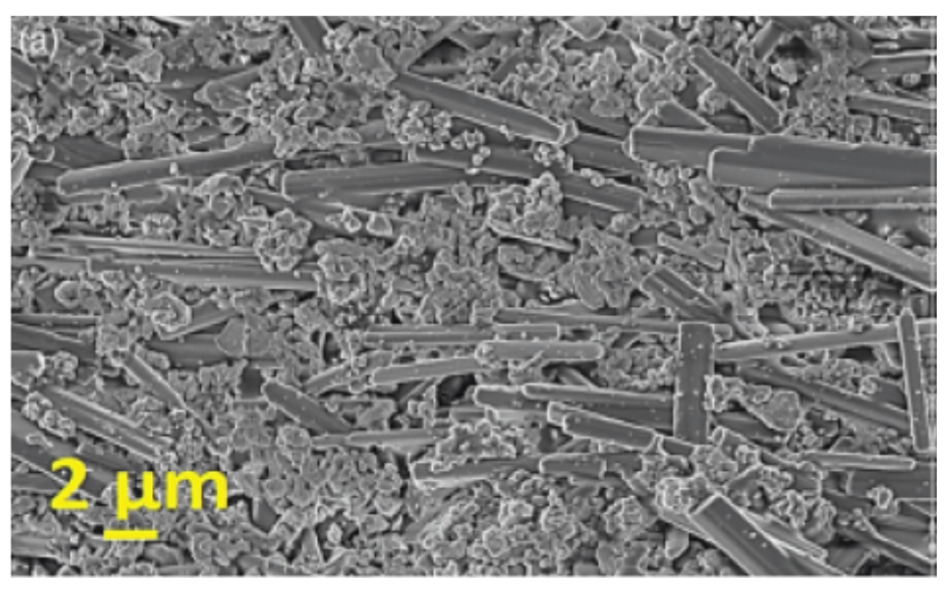
4. Texturing of Lead-Free Piezoelectric Ceramics

| Preparation Method | Conventional Sintering | RTGG Sintered | RTGG Hot-Pressed |
|---|---|---|---|
| Relative density (%) | 99.2 | 97.0 | 98.6 |
| Lotgering factor | 0 | 0.92 | 0.90 |
| ε33/εo (at 1 kHz) | 593 | 595 | 644 |
| tan δ (at 1 kHz) | 0.025 | 0.014 | 0.013 |
| Poisson’s ratio | 0.250 | 0.180 | 0.176 |
| Kt | 0.427 | 0.443 | 0.467 |
| Kp | 0.295 | 0.402 | 0.431 |
| d31 (pC/N) | 36.7 | 57.4 | 63.1 |
| g31 (10−3 Vm/N) | 7.21 | 11.2 | 11.4 |


| BNT-Based System | Template Type | Lotgering Factor (%) | Small Signal Piezoelectric Coefficient (pC/N) | Reference |
|---|---|---|---|---|
| BNT-15BKT (hot-pressed) | Bi4Ti3O12 | ~90 | d31 = 63.1 | Tani [115] |
| BNT-5.5BT | SrTiO3 | ~94 | d33 = 200 | Yilmaz, et al. [119] |
| BNT-15BKT | Bi4Ti3O12 | ~90 | d31 = 50 | Fukuchi, et al. [120] |
| BNT-6BT | Bi4Ti3O12 | ~90 | d31 = −31.4 | Kimura, et al. [122] |
| BNKT-BT | Bi0.5Na0.5TiO3 | ~89 | d33 = 215 | Zheng, et al. [125] |
| BNT-6BT | Bi0.5Na0.5TiO3 | ~87 | d33 = 299 | Zhao, et al. [126] |
| BNT-7BT | Na2Ti6O13 | ~7 | d33 = 216 | Maurya, et al. [129] |
| BNT-7BT | Bi0.5Na0.5TiO3 | ~92 | d33 = 322 | Maurya, et al. [130] |
| BNT-BT-BKT | BaTiO3 | ~93 | d33 = 190 | Maurya, et al. [131] |
| BNT-6BZ | Bi0.5Na0.5TiO3 | ~83 | d33 = 22 | Hussain, et al. [133] |
| BNT-6BT-3AN | Bi0.5Na0.5TiO3 | ~71 | d33 = 766 at 5 kV | Zhang, et al. [134] |
5. Features of Actuator Materials
5.1. Strain
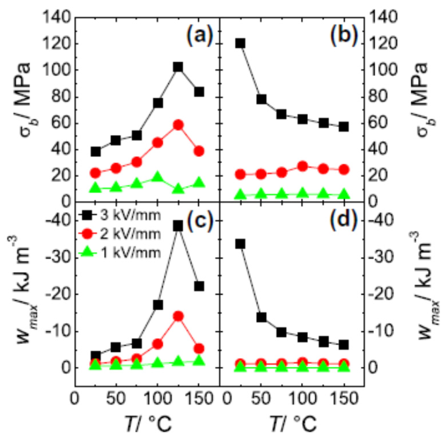
5.2. Blocking Force
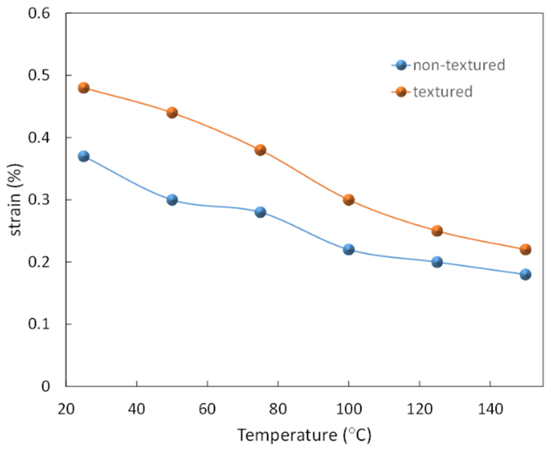
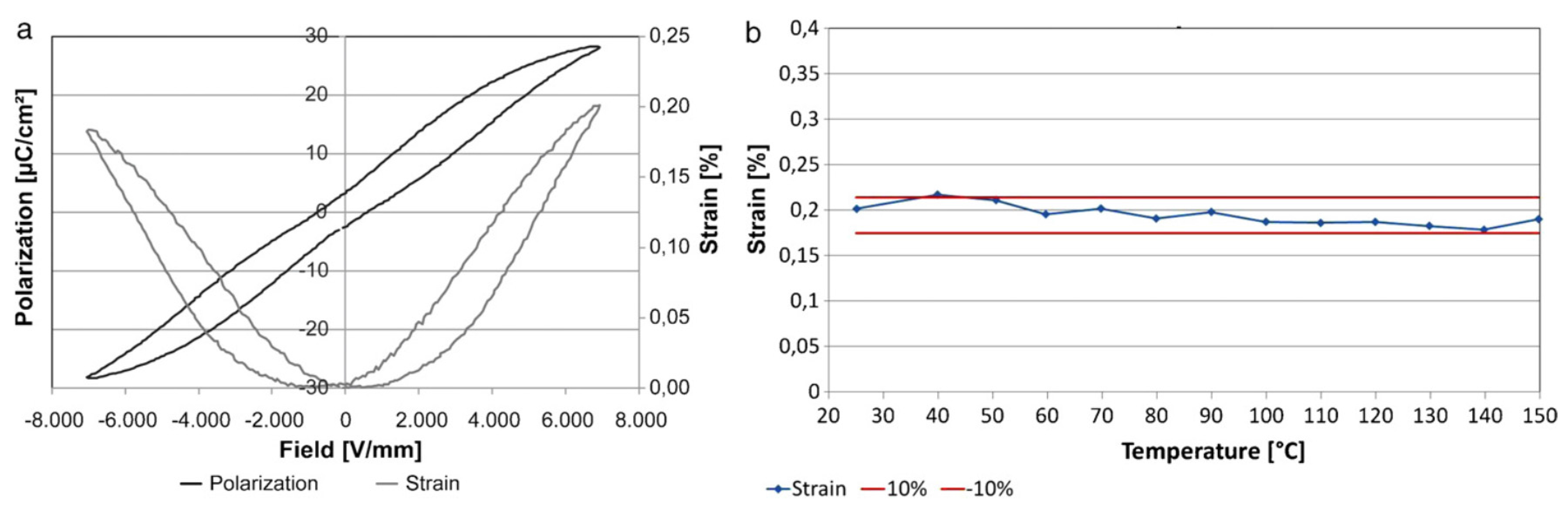
5.3. Temperature Dependence of Strain

5.4. Degradation
5.5. Interaction with Electrode
6. Summary
Acknowledgments
Author Contributions
Conflicts of Interest
References
- Rödel, J.; Webber, K.G.; Dittmer, R.; Wook, J.; Kimura, M.; Damjanovic, D. Transferring lead-free piezoelectric ceramics into application. J. Eur. Ceram. Soc. 2015, 35, 1659–1681. [Google Scholar] [CrossRef]
- Liu, W.F.; Ren, X.B. Large piezoelectric effect in Pb-free ceramics. Phys. Rev. Lett. 2009, 103. [Google Scholar] [CrossRef] [PubMed]
- Damjanovic, D.; Biancoli, A.; Batooli, L.; Vahabzadeh, A.; Trodahl, J. Elastic, dielectric, and piezoelectric anomalies and Raman spec-troscopy of 0.5Ba(Ti0.8Zr0.2)O3-0.5(Ba0.7Ca0.3)TiO3. Appl. Phys. Lett. 2012, 100, 192907. [Google Scholar] [CrossRef]
- Ehmke, M.C.; Ehrlich, S.N.; Blendell, J.E.; Bowman, K.J. Phase coexistence and ferroelastic texture in high strain (1−x)Ba(Zr0.2Ti0.8)O3–x(Ba0.7Ca0.3)TiO3. J. Appl. Phys. 2012, 111, 124110. [Google Scholar] [CrossRef]
- Hao, J.; Bai, W.; Li, W.; Zhai, J. Correlation between the microstructure andelectrical properties in high-performance (Ba0.85Ca0.15)(Zr0.1Ti0.9)O3 lead-free piezoelectric ceramics. J. Am. Ceram. Soc. 2012, 95, 1998–2006. [Google Scholar] [CrossRef]
- Brandt, D.R.J.; Acosta, M.; Koruza, J.; Webber, K.G. Mechanical constitutive behavior and exceptional blocking force of lead-free BZT-xBCT piezoceramics. J. Appl. Phys. 2014, 115, 204107. [Google Scholar] [CrossRef]
- Shrout, T.R.; Zhang, S.J. Lead-free piezoelectric ceramics: Alternatives for PZT? J. Electroceram. 2007, 19, 113–126. [Google Scholar] [CrossRef]
- Wang, K.; Yao, F.-Z.; Jo, W.; Gobeljic, D.; Shvartsman, V.V.; Lupascu, D.C.; Li, J.-F.; Rödel, J. Temperature-insensitive (K,Na)NbO3-based lead-free piezoactuator ceramics. Adv. Funct. Mater. 2013, 23, 4079–4086. [Google Scholar] [CrossRef]
- Hollenstein, E.; Davis, M.; Damjanovic, D.; Setter, N. Piezoelectric properties of Li- and Ta-modified (K0.5Na0.5)NbO3 ceramics. Appl. Phys. Lett. 2005, 87, 182905. [Google Scholar] [CrossRef]
- Matsubara, M.; Yamaguchi, T.; Kikuta, K.; Hirano, S. Sinterability and piezoelectric properties of (K,Na)NbO3 ceramics with novel sintering aid. Jpn. J. Appl. Phys. 2004, 43, 7159–7163. [Google Scholar] [CrossRef]
- Dittmer, R.; Webber, K.G.; Aulbach, E.; Jo, W.; Tan, X.; Rödel, J. Electric-field-induced polarization and strain in 0.94(Bi1/2Na1/2)TiO3-0.06BaTiO3 under uniaxial stress. Acta Mater. 2013, 61, 1350–1358. [Google Scholar] [CrossRef]
- Anton, E.-M.; Jo, W.; Damjanovic, D.; Rödel, J. Determination of depolarization temperature of (Bi1/2Na1/2)TiO3-based lead-free piezoceramics. J. Appl. Phys. 2011, 110, 094108. [Google Scholar] [CrossRef]
- Takenaka, T.; Nagata, H. Current status and prospects of lead-free piezoelectric ceramics. J. Eur. Ceram. Soc. 2005, 25, 2693–2700. [Google Scholar] [CrossRef]
- Zhang, S.-T.; Kounga, A.B.; Aulbach, E.; Deng, Y. Temperature-dependent electrical properties of 0.94Bi0.5Na0.5TiO3-0.06BaTiO3 ceramics. J. Am. Ceram. Soc. 2008, 91, 3950–3954. [Google Scholar] [CrossRef]
- Hiruma, Y.; Imai, Y.; Watanabe, Y.; Nagata, H.; Takenaka, T. Large electrostrain near the phase transition temperature of (Bi0.5Na0.5)TiO3-SrTiO3 ferroelectric ceramics. Appl. Phys. Lett. 2008, 92. [Google Scholar] [CrossRef]
- Hiruma, Y.; Nagata, H.; Takenaka, T. Phase diagrams and electrical properties of (Bi1/2Na1/2)TiO3-based solid solutions. J. Appl. Phys. 2008, 104. [Google Scholar] [CrossRef]
- Zhang, S.-T.; Kounga, A.B.; Jo, W.; Jamin, C.; Seifert, K.; Granzow, T.; Rodel, J.; Damjanovic, D. High-strain lead-free antiferroelectric electrostrictors. Adv. Mater. 2009, 21, 4716–4720. [Google Scholar] [CrossRef]
- Zhang, S.T.; Kounga, A.B.; Aulbach, E.; Granzow, T.; Jo, W.; Kleebe, H.J.; Rödel, J. Lead-free piezoceramics with giant strain in the system Bi0.5Na0.5TiO3-BaTiO3-K0.5Na0.5NbO3. I. Structure and room temperature properties. J. Appl. Phys. 2008, 103, 034107. [Google Scholar] [CrossRef]
- Zhang, S.T.; Kounga, A.B.; Aulbach, E.; Jo, W.; Granzow, T.; Ehrenberg, H.; Rödel, J. Lead-free piezoceramics with giant strain in the system Bi0.5Na0.5TiO3-BaTiO3-K0.5Na0.5NbO3. II. Temperature dependent properties. J. Appl. Phys. 2008, 103, 034108. [Google Scholar] [CrossRef]
- Acosta, M.; Jo, W.; Rödel, J. Temperature and frequency dependent properties of the 0.75Bi1/2Na1/2TiO3-0.25SrTiO3 lead-free incipient piezoceramic. J. Am. Ceram. Soc. 2014, 97, 1937–1943. [Google Scholar] [CrossRef]
- Malik, R.A.; Kang, J.-K.; Hussain, A.; Ahn, C.-W.; Han, H.-S.; Lee, J.-S. High strain in lead-free Nb-doped Bi1/2(Na0.84K0.16)1/2TiO3–SrTiO3 incipient piezoelectric ceramics. Appl. Phys. Express 2014, 7, 061502. [Google Scholar] [CrossRef]
- Saito, Y.; Takao, H.; Tani, T.; Nonoyama, T.; Takatori, K.; Homma, T.; Nagaya, T.; Nakamura, M. Lead-free piezoceramics. Nature 2004, 432, 84–87. [Google Scholar] [CrossRef] [PubMed]
- Smolenskii, G.; Isupov, V.; Agranovskaya, A.; Krainik, N. New ferroelectrics of complex composition. Sov. Phys. Solid State 1961, 2, 2651–2654. [Google Scholar]
- Buhrer, C.F. Some properties of bismuth perovskites. J. Chem. Phys. 1962, 36, 798–803. [Google Scholar] [CrossRef]
- Ivanova, V.; Kapyshev, A.; Venevtsev, Y.N.; Zhdanov, G. X-ray determination of the symmetry of elementary cells of the ferroelectric materials (K0.5Bi0.5)TiO3 and (Na0.5Bi0.5)TiO3 and of high-temperature phase transitions in (K0.5Bi0.5)TiO3. Izv. Akad. Nauk SSSR Seriya Fiz. 1962, 26, 354–356. [Google Scholar]
- Zvirgzds, J.A.; Kapostin, P.P.; Zvirgzde, J.V.; Kruzina, T.V. X-ray study of phase transitions in ferroelectric Na0.5Bi0.5TiO3. Ferroelectrics 1982, 40, 75–77. [Google Scholar] [CrossRef]
- Glazer, A. The classification of tilted octahedra in perovskites. Acta Crystallogr. Sect. B 1972, 28, 3384–3392. [Google Scholar] [CrossRef]
- Vakhrushev, S.; Ivanitskij, B.; Kvyatkovskij, B.; Majstrenko, A.; Malysheva, R.; Okuneva, N.; Parfenova, N. Neutron-diffraction study on sodium-bismuth titanate. Sov. Phys. Solid State 1983, 25, 1504–1506. [Google Scholar]
- Jones, G.O.; Thomas, P.A. Investigation of the structure and phase transitions in the novel A-site substituted distorted perovskite compound Na0.5Bi0.5TiO3. Acta Crystallogr. Sect. B 2002, 58, 168–178. [Google Scholar] [CrossRef]
- Isuyov, V.A.; Pronin, I.P.; Kruzina, T.V. Temperature dependence of bireringence and opalescence of the sodium-bismuth titanate crystals. Ferroelectr. Lett. Sect. 1984, 2, 205–208. [Google Scholar] [CrossRef]
- Kreisel, J.; Bouvier, P.; Dkhil, B.; Thomas, P.A.; Glazer, A.M.; Welberry, T.R.; Chaabane, B.; Mezouar, M. High-pressure X-ray scattering of oxides with a nanoscale local structure: Application to Na1/2Bi1/2TiO3. Phys. Rev. B 2003, 68, 014113. [Google Scholar] [CrossRef]
- Shuvaeva, V.A.; Zekria, D.; Glazer, A.M.; Jiang, Q.; Weber, S.M.; Bhattacharya, P.; Thomas, P.A. Local structure of the lead-free relaxor ferroelectric (KxNa1–x)0.5Bi0.5TiO3. Phys. Rev. B 2005, 71, 174114. [Google Scholar] [CrossRef]
- Balagurov, A.M.; Koroleva, E.Y.; Naberezhnov, A.A.; Sakhnenko, V.P.; Savenko, B.N.; Ter-Oganessian, N.V.; Vakhrushev, S.B. The rhombohedral phase with incommensurate modulation in Na1/2Bi1/2TiO3. Phase Transit. 2006, 79, 163–173. [Google Scholar] [CrossRef]
- Keeble, D.S.; Barney, E.R.; Keen, D.A.; Tucker, M.G.; Kreisel, J.; Thomas, P.A. Bifurcated polarization rotation in bismuth-based piezoelectrics. Adv. Funct. Mater. 2012, 23, 185–190. [Google Scholar] [CrossRef]
- Aksel, E.; Forrester, J.S.; Nino, J.C.; Page, K.; Shoemaker, D.P.; Jones, J.L. Local atomic structure deviation from average structure of Na0.5Bi0.5TiO3: Combined X-ray and neutron total scattering study. Phys. Rev. B 2013, 87, 104113. [Google Scholar] [CrossRef]
- Gorfman, S.; Thomas, P.A. Evidence for a non-rhombohedral average structure in the lead-free piezoelectric material Na0.5Bi0.5TiO3. J. Appl. Crystallogr. 2010, 43, 1409–1414. [Google Scholar] [CrossRef]
- Aksel, E.; Forrester, J.S.; Jones, J.L.; Thomas, P.A.; Page, K.; Suchomel, M.R. Monoclinic crystal structure of polycrystalline Na0.5Bi0.5TiO3. Appl. Phys. Lett. 2011, 98, 152901. [Google Scholar] [CrossRef]
- Aksel, E.; Forrester, J.S.; Kowalski, B.; Jones, J.L.; Thomas, P.A. Phase transition sequence in sodium bismuth titanate observed using high-resolution X-ray diffraction. Appl. Phys. Lett. 2011, 99, 222901. [Google Scholar] [CrossRef]
- Rao, B.N.; Datta, R.; Chandrashekaran, S.S.; Mishra, D.K.; Sathe, V.; Senyshyn, A.; Ranjan, R. Local structural disorder and its influence on the average global structure and polar properties in Na0.5Bi0.5TiO3. Phys. Rev. B 2013, 88, 224103. [Google Scholar] [CrossRef]
- Rao, B.N.; Ranjan, R. Electric-field-driven monoclinic-to-rhombohedral transformation in Na1/2Bi1/2TiO3. Phys. Rev. B 2012, 86, 134103. [Google Scholar] [CrossRef]
- Rao, B.N.; Fitch, A.N.; Ranjan, R. Ferroelectric-ferroelectric phase coexistence in Na1/2Bi1/2TiO3. Phys. Rev. B 2013, 87, 060102. [Google Scholar] [CrossRef]
- Beanland, R.; Thomas, P.A. Symmetry and defects in rhombohedral single-crystalline Na0.5Bi0.5TiO3. Phys. Rev. B 2014, 89, 174102. [Google Scholar] [CrossRef]
- Dorcet, V.; Trolliard, G. A transmission electron microscopy study of the A-site disordered perovskite Na0.5Bi0.5TiO3. Acta Mater. 2008, 56, 1753–1761. [Google Scholar] [CrossRef]
- Beanland, R.; Thomas, P.A. Imaging planar tetragonal sheets in rhombohedral Na0.5Bi0.5TiO3 using transmission electron microscopy. Scr. Mater. 2011, 65, 440–443. [Google Scholar] [CrossRef]
- Levin, I.; Reaney, I.M. Nano- and mesoscale structure of Na1/2Bi1/2TiO3: A TEM perspective. Adv. Funct. Mater. 2012, 22, 3445–3452. [Google Scholar] [CrossRef]
- Ma, C.; Guo, H.; Tan, X. A new phase boundary in (Bi1/2Na1/2)TiO3–BaTiO3 revealed via a novel method of electron diffraction analysis. Adv. Funct. Mater. 2013, 23, 5261–5266. [Google Scholar] [CrossRef]
- King, G.; Woodward, P.M. Cation ordering in perovskites. J. Mater. Chem. 2010, 20, 5785–5796. [Google Scholar] [CrossRef]
- Davies, P.; Wu, H.; Borisevich, A.; Molodetsky, I.; Farber, L. Crystal chemistry of complex perovskites: New cation-ordered dielectric oxides. Annu. Rev. Mater. Res. 2008, 38, 369–401. [Google Scholar] [CrossRef]
- Shannon, R.D. Revised effective ionic radii and systematic studies of interatomic distances in halides and chalcogenides. Acta Crystallogr. Sect. A 1976, 32, 751–767. [Google Scholar] [CrossRef]
- Groeting, M.; Hayn, S.; Albe, K. Chemical order and local structure of the lead-free relaxor ferroelectric Na1/2Bi1/2TiO3. J. Solid State Chem. 2011, 184, 2041–2046. [Google Scholar] [CrossRef]
- Park, S.E.; Chung, S.J.; Kim, I.T.; Hong, K.S. Nonstoichiometry and the long-range cation ordering in crystals of (Na1/2Bi1/2)TiO3. J. Am. Ceram. Soc. 1994, 77, 2641–2647. [Google Scholar] [CrossRef]
- Siny, I.; Smirnova, T.; Kruzina, T. The phase transition dynamics in Na1/2Bi1/2TiO3. Ferroelectrics 1991, 124, 207–212. [Google Scholar] [CrossRef]
- Petzelt, J.; Kamba, S.; Fabry, J.; Noujni, D.; Porokhonskyy, V.; Pashkin, A.; Franke, I.; Roleder, K.; Suchanicz, J.; Klein, R.; et al. Infrared, Raman and high-frequency dielectric spectroscopy and the phase transitions in Na1/2Bi1/2TiO3. J. Phys. Condens. Matter 2004, 16, 2719–2731. [Google Scholar] [CrossRef]
- Hiruma, Y.; Nagata, H.; Takenaka, T. Thermal depoling process and piezoelectric properties of bismuth sodium titanate ceramics. J. Appl. Phys. 2009, 105, 084112. [Google Scholar] [CrossRef]
- Pronin, I.P.; Syrnikov, P.P.; Isupov, V.A.; Egorov, V.M.; Zaitseva, N.V. Peculiarities of phase transitions in sodium-bismuth titanate. Ferroelectrics 1980, 25, 395–397. [Google Scholar] [CrossRef]
- Kruzina, T.; Duda, V.; Suchanicz, J. Peculiarities of optical behaviour of Na0.5Bi0.5TiO3 single crystals. Mater. Sci. Eng. B 2001, 87, 48–52. [Google Scholar] [CrossRef]
- Sakata, K.; Masuda, Y. Ferroelectric and antiferroelectric properties of (Na0.5Bi0.5)TiO3-SrTiO3 solid solution ceramics. Ferroelectrics 1974, 7, 347–349. [Google Scholar] [CrossRef]
- Vakhrushev, S.; Okuneva, N.; Plachenova, É.; Syrnikov, P. Phase transitions in sodium-bismuth titanate. JETP Lett. 1982, 35, 134–137. [Google Scholar]
- Vakhrushev, S.; Isupov, V.; Kvyatkovsky, B.; Okuneva, N.; Pronin, I.; Smolensky, G.; Syrnikov, P. Phase transitions and soft modes in sodium bismuth titanate. Ferroelectrics 1985, 63, 153–160. [Google Scholar] [CrossRef]
- Zhang, M.-S.; Scott, J.; Zvirgzds, J. Raman spectroscopy of Na0.5Bi0.5TiO3. Ferroelectr. Lett. Sect. 1986, 6, 147–152. [Google Scholar] [CrossRef]
- Suchanicz, J.; Roleder, K.; Kania, A.; Hańaderek, J. Electrostrictive strain and pyroeffect in the region of phase coexistence in Na0.5Bi0.5TiO3. Ferroelectrics 1988, 77, 107–110. [Google Scholar] [CrossRef]
- Suchanicz, J.; Ptak, W.S. On the phase transition in Na0.5Bi0.5TiO3. Ferroelectr. Lett. Sect. 1990, 12, 71–78. [Google Scholar] [CrossRef]
- Suchanicz, J.; Kwapulinski, J. X-ray diffraction study of the phase transitions in Na0.5Bi0.5TiO3. Ferroelectrics 1995, 165, 249–253. [Google Scholar] [CrossRef]
- Suchanicz, J. Investigations of the phase transitions in Na0.5Bi0.5TiO3. Ferroelectrics 1995, 172, 455–458. [Google Scholar] [CrossRef]
- Suchanicz, J. Peculiarities of phase transitions in Na0.5Bi0.5TiO3. Ferroelectrics 1997, 190, 77–81. [Google Scholar] [CrossRef]
- Jones, G.O.; Kreisel, J.; Jennings, V.; Geday, M.A.; Thomas, P.A.; Glazer, A.M. Investigation of a peculiar relaxor ferroelectric: Na0.5Bi0.5TiO3. Ferroelectrics 2002, 270, 191–196. [Google Scholar] [CrossRef]
- Li, M.; Li, L.; Zang, J.; Sinclair, D.C. Donor-doping and reduced leakage current in Nb-doped Na0.5Bi0.5TiO3. Appl. Phys. Lett. 2015, 106, 102904. [Google Scholar] [CrossRef]
- Dorcet, V.; Trolliard, G.; Boullay, P. Reinvestigation of phase transitions in Na0.5Bi0.5TiO3 by TEM. Part I: First order rhombohedral to orthorhombic phase transition. Chem. Mater. 2008, 20, 5061–5073. [Google Scholar] [CrossRef]
- Trolliard, G.; Dorcet, V. Reinvestigation of phase transitions in Na0.5Bi0.5TiO3 by TEM. Part II: Second order orthorhombic to tetragonal phase transition. Chem. Mater. 2008, 20, 5074–5082. [Google Scholar] [CrossRef]
- Dorcet, V.; Trolliard, G.; Boullay, P. The structural origin of the antiferroelectric properties and relaxor behavior of Na0.5Bi0.5TiO3. J. Magn. Magn. Mater. 2009, 321, 1758–1761. [Google Scholar] [CrossRef]
- Jaffe, B.; Cook, W.R.; Jaffe, H. Piezoelectric Ceramics; Academic Press Inc.: London, UK, 1971. [Google Scholar]
- Takenaka, T.; Maruyama, K.-I.; Sakata, K. (Bi1/2Na1/2)TiO3-BaTiO3 system for lead-free piezoelectric ceramics. Jpn. J. Appl. Phys. Part 1 1991, 30, 2236–2239. [Google Scholar] [CrossRef]
- Sasaki, A.; Chiba, T.; Mamiya, Y.; Otsuki, E. Dielectric and piezoelectric properties of (Bi0.5Na0.5)TiO3-(Bi0.5K0.5)TiO3 systems. Jpn. J. Appl. Phys. Part 1 1999, 38, 5564–5567. [Google Scholar] [CrossRef]
- Chu, B.J.; Chen, D.R.; Li, G.R.; Yin, Q.R. Electrical properties of Na1/2Bi1/2TiO3-BaTiO3 ceramics. J. Eur. Ceram. Soc. 2002, 22, 2115–2121. [Google Scholar] [CrossRef]
- Wang, X.X.; Tang, X.G.; Chan, H.L.W. Electromechanical and ferroelectric properties of (Bi1/2K1/2)TiO3–(Bi1/2Na1/2)TiO3–BaTiO3 lead-free piezoelectric ceramics. Appl. Phys. Lett. 2004, 85, 91–93. [Google Scholar] [CrossRef]
- Isupov, V.A. Ferroelectric Na0.5Bi0.5TiO3 and K0.5Bi0.5TiO3 perovskites and their solid solutions. Ferroelectrics 2005, 315, 123–147. [Google Scholar] [CrossRef]
- Zhang, S.-T.; Kounga, A.B.; Aulbach, E.; Ehrenberg, H.; Roedel, J. Giant strain in lead-free piezoceramics Na0.5Bi0.5TiO3-BaTiO3-K0.5Na0.5NbO3 system. Appl. Phys. Lett. 2007, 91, 112906. [Google Scholar] [CrossRef]
- Jo, W.; Granzow, T.; Aulbach, E.; Rödel, J.; Damjanovic, D. Origin of the large strain response in (K0.5Na0.5)NbO3-modified (Bi0.5Na0.5)TiO3–BaTiO3 lead-free piezoceramics. J. Appl. Phys. 2009, 105, 094102. [Google Scholar] [CrossRef]
- Guo, Y.; Liu, Y.; Withers, R.L.; Brink, F.; Chen, H. Large electric field-induced strain and antiferroelectric behavior in (1−x)(Na0.5Bi0.5)TiO3−xBaTiO3 ceramics. Chem. Mater. 2011, 23, 219–228. [Google Scholar] [CrossRef]
- Jo, W.; Daniels, J.E.; Jones, J.L.; Tan, X.; Thomas, P.A.; Damjanovic, D.; Roedel, J. Evolving morphotropic phase boundary in lead-free (Bi1/2Na1/2)TiO3-BaTiO3 piezoceramics. J. Appl. Phys. 2011, 109, 014110. [Google Scholar] [CrossRef]
- Jo, W.; Schaab, S.; Sapper, E.; Schmitt, L.A.; Kleebe, H.-J.; Bell, A.J.; Roedel, J. On the phase identity and its thermal evolution of lead free (Bi1/2Na1/2)TiO3-6 mol % BaTiO3. J. Appl. Phys. 2011, 110, 074106. [Google Scholar] [CrossRef]
- Wylie-van Eerd, B.; Damjanovic, D.; Klein, N.; Setter, N.; Trodahl, J. Structural complexity of (Na0.5Bi0.5)TiO3−BaTiO3 as revealed by Raman spectroscopy. Phys. Rev. B 2010, 82, 104112. [Google Scholar] [CrossRef]
- Ma, C.; Tan, X. Phase diagram of unpoled lead-free (1−x) (Bi1/2Na1/2)TiO3–xBaTiO3 ceramics. Solid State Commun. 2010, 150, 1497–1500. [Google Scholar] [CrossRef]
- Anton, E.-M.; Schmitt, L.A.; Hinterstein, M.; Trodahl, J.; Kowalski, B.; Jo, W.; Kleebe, H.-J.; Rödel, J.; Jones, J.L. Structure and temperature-dependent phase transitions of lead-free Bi1/2Na1/2TiO3–Bi1/2K1/2TiO3–K0.5Na0.5NbO3 piezoceramics. J. Mater. Res. 2012, 27, 2466–2478. [Google Scholar] [CrossRef]
- Dittmer, R.; Anton, E.-M.; Jo, W.; Simons, H.; Daniels, J.E.; Hoffman, M.; Pokorny, J.; Reaney, I.M.; Rödel, J. A high-temperature-capacitor dielectric based on K0.5Na0.5NbO3-modified Bi1/2Na1/2TiO3–Bi1/2K1/2TiO3. J. Am. Ceram. Soc. 2012, 95, 3519–3524. [Google Scholar] [CrossRef]
- Zang, J.; Li, M.; Sinclair, D.C.; Frömling, T.; Jo, W.; Rödel, J. Impedance spectroscopy of (Bi1/2Na1/2)TiO3–BaTiO3 based high-temperature dielectrics. J. Am. Ceram. Soc. 2014, 97, 2825–2831. [Google Scholar] [CrossRef]
- Zang, J.; Li, M.; Sinclair, D.C.; Jo, W.; Rödel, J. Impedance spectroscopy of (Bi1/2Na1/2)TiO3–BaTiO3 ceramics modified with (K0.5Na0.5)NbO3. J. Am. Ceram. Soc. 2014, 97, 1523–1529. [Google Scholar] [CrossRef]
- Nagata, H.; Yoshida, M.; Makiuchi, Y.; Takenaka, T. Large piezoelectric constant and high Curie temperature of lead-free piezoelectric ceramic ternary system based on bismuth sodium titanate-bismuth potassium titanate-barium titanate near the morphotropic phase boundary. Jpn. J. Appl. Phys. Part 1 2003, 42, 7401–7403. [Google Scholar] [CrossRef]
- Zhang, S.-T.; Yan, F.; Yang, B.; Cao, W. Phase diagram and electrostrictive properties of Bi0.5Na0.5TiO3–BaTiO3– K0.5Na0.5NbO3 ceramics. Appl. Phys. Lett. 2010, 97, 122901. [Google Scholar] [CrossRef]
- Gröting, M.; Albe, K. Theoretical prediction of morphotropic compositions in Na1/2Bi1/2TiO3-based solid solutions from transition pressures. Phys. Rev. B 2014, 89, 054105. [Google Scholar] [CrossRef]
- Ma, C.; Guo, H.; Beckman, S.P.; Tan, X. Creation and destruction of morphotropic phase boundaries through electrical poling: A case study of lead-free (Bi1/2Na1/2)TiO3−BaTiO3 piezoelectrics. Phys. Rev. Lett. 2012, 109, 107602. [Google Scholar] [CrossRef] [PubMed]
- Elkechai, O.; Manier, M.; Mercurio, J.P. Na0.5Bi0.5TiO3–K0.5Bi0.5TiO3 (NBT-KBT) system: A structural and electrical study. Phys. Status Solidi A 1996, 157, 499–506. [Google Scholar] [CrossRef]
- Jones, G.O.; Kreisel, J.; Thomas, P.A. A structural study of the (Na1−xKx)0.5Bi0.5TiO3 perovskite series as a function of substitution (x) and temperature. Powder Diffr. 2002, 17, 301–319. [Google Scholar] [CrossRef]
- Xie, H.; Jin, L.; Shen, D.; Wang, X.; Shen, G. Morphotropic phase boundary, segregation effect and crystal growth in the NBT–KBT system. J. Cryst. Growth 2009, 311, 3626–3630. [Google Scholar] [CrossRef]
- Zuo, R.Z.; Su, S.; Wu, Y.; Fu, J.; Wang, M.; Li, L.T. Influence of A-site nonstoichiometry on sintering, microstructure and electrical properties of (Bi0.5Na0.5)TiO3 ceramics. Mater. Chem. Phys. 2008, 110, 311–315. [Google Scholar] [CrossRef]
- Sung, Y.S.; Kim, J.M.; Cho, J.H.; Song, T.K.; Kim, M.H.; Chong, H.H.; Park, T.G.; Do, D.; Kim, S.S. Effects of Na nonstoichiometry in Bi0.5Na(0.5+x)TiO3 ceramics. Appl. Phys. Lett. 2010, 96, 022901. [Google Scholar] [CrossRef]
- Sung, Y.S.; Kim, J.M.; Cho, J.H.; Song, T.K.; Kim, M.H.; Park, T.G. Effects of Bi nonstoichiometry in Bi(0.5+x)Na0.5TiO3 ceramics. Appl. Phys. Lett. 2011, 98, 012902. [Google Scholar] [CrossRef]
- Jeong, I.-K.; Sung, Y.; Song, T.; Kim, M.-H.; Llobet, A. Structural evolution of bismuth sodium titanate induced by A-site non-stoichiometry: Neutron powder diffraction studies. J. Korean Phys. Soc. 2015, 9. [Google Scholar] [CrossRef]
- Carter, J.; Aksel, E.; Iamsasri, T.; Forrester, J.S.; Chen, J.; Jones, J.L. Structure and ferroelectricity of nonstoichiometric (Na0.5Bi0.5)TiO3. Appl. Phys. Lett. 2014, 104, 112904. [Google Scholar] [CrossRef]
- Naderer, M.; Kainz, T.; Schütz, D.; Reichmann, K. The influence of Ti-nonstoichiometry in Bi0.5Na0.5TiO3. J. Eur. Ceram. Soc. 2014, 34, 663–667. [Google Scholar] [CrossRef]
- Spreitzer, M.; Valant, M.; Suvorov, D. Sodium deficiency in Na0.5Bi0.5TiO3. J. Mater. Chem. 2007, 17, 185–192. [Google Scholar] [CrossRef]
- Li, M.; Pietrowski, M.J.; de Souza, R.A.; Zhang, H.; Reaney, I.M.; Cook, S.N.; Kilner, J.A.; Sinclair, D.C. A family of oxide ion conductors based on the ferroelectric perovskite Na0.5Bi0.5TiO3. Nat. Mater. 2014, 13, 31–35. [Google Scholar] [CrossRef] [PubMed]
- Li, M.; Zhang, H.; Cook, S.N.; Li, L.; Kilner, J.A.; Reaney, I.M.; Sinclair, D.C. Dramatic influence of A-site nonstoichiometry on the electrical conductivity and conduction mechanisms in the perovskite oxide Na0.5Bi0.5TiO3. Chem. Mater. 2015, 27, 629–634. [Google Scholar] [CrossRef]
- Smyth, D.M. The Defect Chemistry of Metal Oxides; Oxford University Press: New York, NY, USA, 2000. [Google Scholar]
- Bousquet, M.; Duclere, J.R.; Orhan, E.; Boulle, A.; Bachelet, C.; Champeaux, C. Optical properties of an epitaxial Na0.5Bi0.5TiO3 thin film grown by laser ablation: Experimental approach and density functional theory calculations. J. Appl. Phys. 2010, 107, 104107. [Google Scholar] [CrossRef]
- Kim, C.Y.; Sekino, T.; Niihara, K. Optical, mechanical, and dielectric properties of Bi1/2Na1/2TiO3 thin film synthesized by sol-gel method. J. Sol-Gel Sci. Technol. 2010, 55, 306–310. [Google Scholar] [CrossRef]
- Zeng, M.; Or, S.W.; Chan, H.L.W. First-principles study on the electronic and optical properties of Na0.5Bi0.5TiO3 lead-free piezoelectric crystal. J. Appl. Phys. 2010, 107, 043513. [Google Scholar] [CrossRef]
- Schütz, D.; Deluca, M.; Krauss, W.; Feteira, A.; Jackson, T.; Reichmann, K. Lone-pair-induced covalency as the cause of temperature- and field-induced instabilities in bismuth sodium titanate. Adv. Funct. Mater. 2012, 22, 2285–2294. [Google Scholar] [CrossRef]
- Krauss, W.; Schütz, D.; Mautner, F.A.; Feteira, A.; Reichmann, K. Piezoelectric properties and phase transition temperatures of the solid solution of (1–x) (Bi0.5Na0.5)TiO3–xSrTiO3. J. Eur. Ceram. Soc. 2010, 30, 1827–1832. [Google Scholar] [CrossRef]
- Jo, W.; Dittmer, R.; Acosta, M.; Zang, J.; Groh, C.; Sapper, E.; Wang, K.; Rödel, J. Giant electric-field-induced strains in lead-free ceramics for actuator applications—Status and perspective. J. Electroceram. 2012, 29, 71–93. [Google Scholar] [CrossRef]
- Takenaka, T.; Nagata, H.; Hiruma, Y. Phase-transition temperatures and piezoelectric properties of (Bi1/2Na1/2)TiO3 and (Bi1/2K1/2)TiO3–based bismuth perovskite lead-free ferroelectric ceramics. IEEE TUFFC 2009, 56, 1595–1612. [Google Scholar] [CrossRef] [PubMed]
- Watanabe, Y.; Hiruma, Y.; Nagata, H.; Takenaka, T. Phase transition temperature and electrical properties of divalent ions (Ca2+, Sr2+ and Ba2+) substituted (Bi1/2Na1/2)TiO3 ceramics. Ceram. Int. 2008, 34, 761–764. [Google Scholar] [CrossRef]
- Zhang, S.; Kounga, A.; Aulbach, E. Giant strain in lead-free piezoceramics Bi0.5Na0.5TiO3–BaTiO3–K0.5Na0.5NbO3 system. Appl. Phys. Lett. 2007, 91, 112906. [Google Scholar] [CrossRef]
- Chiang, Y.M.; Farrey, G.W.; Soukhojak, A.N. Lead-free high-strain single-crystal piezoelectrics in the alkaline-bismuth-titanate perovskite family. Appl. Phys. Lett. 1998, 73, 3683–3685. [Google Scholar] [CrossRef]
- Tani, T. Crystalline-oriented piezoelectric bulk ceramics with a perovskite-type structure. J. Korean Phys. Soc. 1998, 32, S1217–S1220. [Google Scholar]
- Kimura, T. Application of texture engineering to piezoelectric ceramics—A review. J. Ceram. Soc. Jpn. 2006, 114, 15–25. [Google Scholar] [CrossRef]
- Messing, G.L.; Trolier-McKinstry, S.; Sabolsky, E.M.; Duran, C.; Kwon, S.; Brahmaroutu, B.; Park, P.; Yilmaz, H.; Rehrig, P.W.; Eitel, K.B.; et al. Templated grain growth of textured piezoelectric ceramics. Crit. Rev. Solid State Mater. Sci. 2004, 29, 45–96. [Google Scholar] [CrossRef]
- Yilmaz, H.; Messing, G.L.; Trolier-McKinstry, S. Textured sodium bismuth titanate (Na1/2Bi1/2)0.945Ba0.055TiO3 ceramics by templated grain growth. In Proceedings of the 2000 12th IEEE International Symposium on Applications of Ferroelectrics, Honolulu, HI, USA, 21 July–2 August 2000; pp. 405–408.
- Yilmaz, H.; Trolier-McKinstry, S.; Messing, G.L. (Reactive) templated grain growth of textured sodium bismuth titanate (Na1/2Bi1/2TiO3-BaTiO3) ceramics—II dielectric and piezoelectric properties. J. Electroceram. 2003, 11, 217–226. [Google Scholar] [CrossRef]
- Fukuchi, E.; Kimura, T.; Tani, T.; Takeuch, T.; Saito, Y. Effect of potassium concentration on the grain orientation in bismuth sodium potassium titanate. J. Am. Ceram. Soc. 2002, 85, 1461–1466. [Google Scholar] [CrossRef]
- West, D.L.; Payne, D.A. Microstructure development in reactive-templated grain growth of Bi1/2Na1/2TiO3-based ceramics: Template and formulation effects. J. Am. Ceram. Soc. 2003, 86, 769–774. [Google Scholar] [CrossRef]
- Kimura, T.; Takahashi, T.; Tani, T.; Saito, Y. Crystallographic texture development in bismuth sodium titanate prepared by reactive-templated grain growth method. J. Am. Ceram. Soc. 2004, 87, 1424–1429. [Google Scholar] [CrossRef]
- Kimura, T.; Takahashi, T.; Tani, T.; Saito, Y. Preparation of crystallographically textured Bi0.5Na0.5TiO3–BaTiO3 ceramics by reactive-templated grain growth method. Ceram. Int. 2004, 30, 1161–1167. [Google Scholar] [CrossRef]
- Fuse, K.; Kimura, T. Effect of particle sizes of starting materials on microstructure development in textured Bi0.5(Na0.5K0.5)0.5TiO3. J. Am. Ceram. Soc. 2006, 89, 1957–1964. [Google Scholar] [CrossRef]
- Zeng, J.T.; Kwok, K.W.; Tam, W.K.; Tian, H.Y.; Jiang, X.P.; Chan, H.L.W. Plate-like Na0.5Bi0.5TiO3 template synthesized by a topochemical method. J. Am. Ceram. Soc. 2006, 89, 3850–3853. [Google Scholar] [CrossRef]
- Zhao, W.; Ya, J.; Xin, Y.; Lie, E.; Zhao, D.; Zhou, H. Fabrication of Na0.5Bi0.5TiO3-BaTiO3—Textured ceramics templated by plate-like Na0.5Bi0.5TiO3 particles. J. Am. Ceram. Soc. 2009, 92, 1607–1609. [Google Scholar] [CrossRef]
- Zhao, W.; Zhou, H.; Yan, Y.; Liu, D. Topochemical synthesis of plate-like Na0.5Bi0.5TiO3 from Aurivillius precursor. J. Am. Ceram. Soc. 2008, 91, 1322–1325. [Google Scholar] [CrossRef]
- Gao, F.; Hong, R.-Z.; Liu, J.-J.; Yao, Y.-H.; Tian, C.-S. Effect of different templates on microstructure of textured Na0.5Bi0.5TiO3-BaTiO3 ceramics with RTGG method. J. Eur. Ceram. Soc. 2008, 28, 2063–2070. [Google Scholar] [CrossRef]
- Maurya, D.; Murayama, M.; Priya, S. Synthesis and characterization of Na2Ti6O13 whiskers and their transformation to (1–x) Na0.5Bi0.5TiO3–xBaTiO3 ceramics. J. Am. Ceram. Soc. 2011, 94, 2857–2871. [Google Scholar] [CrossRef]
- Maurya, D.; Zhou, Y.; Yan, Y.; Priya, S. Synthesis mechanism of grain-oriented lead-free piezoelectric Na0.5Bi0.5TiO3-BaTiO3 ceramics with giant piezoelectric response. J. Mater. Chem. C 2013, 1, 2102–2111. [Google Scholar]
- Maurya, D.; Zhou, Y.; Wang, Y.; Yan, Y.; Li, J.; Viehland, D.; Priya, S. Giant strain with ultra-low hysteresis and high temperature stability in grain oriented lead-free K0.5Bi0.5TiO3-BaTiO3-Na0.5Bi0.5TiO3 piezoelectric materials. Sci. Rep. 2015, 5. [Google Scholar] [CrossRef] [PubMed]
- Hu, D.; Mori, K.; Kong, X.; Shinagawa, K.; Wada, S.; Feng, Q. Fabrication of [100] -oriented bismuth sodium titanate ceramics with small grain size and high density for piezoelectric materials. J. Eur. Ceram. Soc. 2014, 34, 1169–1180. [Google Scholar] [CrossRef]
- Hussain, A.; Maqbool, A.; Malik, R.A.; Rahman, J.U.; Song, T.-K.; Kim, W.-J.; Kim, M.-H. Na0.5Bi0.5TiO3–BaZrO3 textured ceramics prepared by reactive templated grain growth method. Ceram. Int. 2015, 41, S26–S30. [Google Scholar] [CrossRef]
- Zhang, H.; Xu, P.; Patterson, E.; Zang, J.; Jiang, S.; Roedel, J. Preparation and enhanced electrical properties of grain-oriented (Bi1/2Na1/2)TiO3-based lead-free incipient piezoceramics. J. Eur. Ceram. Soc. 2015, 35, 2501–2512. [Google Scholar] [CrossRef]
- Randall, C.; Kelnberger, A.; Yang, G.; Eitel, R.; Shrout, T. High strain piezoelectric multilayer actuators—A material science and engineering challenge. J. Electroceram. 2005, 14, 177–191. [Google Scholar] [CrossRef]
- Juuti, J.; Leinonen, M.; Jantunen, H. Micropositioning. In Piezoelectric and Acoustic Materials for Transducer Applications; Safari, A., Akdogan, E.K., Eds.; Springer Science + Business Media: New York, NY, USA, 2008. [Google Scholar]
- Lucato, S.; Lupascu, D.C.; Kamlah, M.; Rödel, J.; Lynch, C.S. Constraint-induced crack initiation at electrode edges in piezoelectric ceramics. Acta Mater. 2001, 49, 2751–2759. [Google Scholar] [CrossRef]
- Koch, J. Piezoxide (PXE)—Eigenschaften und Anwendungen; Dr. Alfred Hüthig Verlag GmbH: Heidelberg, Germany, 1988. [Google Scholar]
- Dittmer, R.; Aulbach, E.; Jo, W.; Webber, K.G.; Rödel, J. Large blocking force in Bi1/2Na1/2TiO3–based lead-free piezoceramics. Scr. Mater. 2012, 67, 100–103. [Google Scholar] [CrossRef]
- Reichmann, K.; Deluca, M.; Schütz, D.; Supancic, P. Load characteristics of lead-free ceramic multilayer actuators based on bismuth-sodium-titanate. Int. J. Appl. Ceram. Technol. 2014, 11, 431–435. [Google Scholar] [CrossRef]
- Krauss, W.; Schütz, D.; Naderer, M.; Orosel, D.; Reichmann, K. BNT-based multilayer device with large and temperature independent strain made by a water-based preparation process. J. Eur. Ceram. Soc. 2011, 31, 1857–1860. [Google Scholar] [CrossRef]
- Zuo, R.; Ye, C.; Fang, X.; Li, J. Tantalum doped 0.94Bi0.5Na0.5TiO3–0.06BaTiO3 piezoelectric ceramics. J. Eur. Ceram. Soc. 2008, 28, 871–877. [Google Scholar] [CrossRef]
- Yang, Z.; Liu, B.; Wei, L.; Hou, Y. Structure and electrical properties of (1–x)Bi0.5Na0.5TiO3–xBi0.5K0.5TiO3 ceramics near morphotropic phase boundary. Mat. Res. Bull. 2008, 43, 81–89. [Google Scholar] [CrossRef]
- Lupascu, D.; Rödel, J. Fatigue in bulk lead zirconate titanate actuator materials. Adv. Eng. Mater. 2005, 7, 882–898. [Google Scholar] [CrossRef]
- Glaum, J.; Hoffman, M. Electric fatigue of lead-free piezoelectric materials. J. Am. Ceram. Soc. 2014, 97, 665–680. [Google Scholar] [CrossRef]
- Genenko, Y.A.; Glaum, J.; Hoffmann, M.J.; Albe, K. Mechanisms of aging and fatigue in ferroelectrics. Mater. Sci. Eng. B 2015, 192, 52–82. [Google Scholar] [CrossRef]
- Luo, Z.; Glaum, J.; Granzow, T.; Jo, W.; Dittmer, R.; Hoffman, M.; Rödel, J. Bipolar and unipolar fatigue of ferroelectric BNT-based lead-free piezoceramics. J. Am. Ceram. Soc. 2011, 94, 529–535. [Google Scholar] [CrossRef]
- Ehmke, M.; Glaum, J.; Jo, W.; Granzow, T.; Rödel, J. Stabilization of the fatigue-resistant phase by CuO addition in (Bi1/2Na1/2)TiO3–BaTiO3. J. Am. Ceram. Soc. 2011, 94, 2473–2478. [Google Scholar] [CrossRef]
- Luo, Z.; Granzow, T.; Glaum, J.; Jo, W.; Rödel, J.; Hoffman, M. Effect of ferroelectric long-range order on the unipolar and bipolar electric fatigue in Bi1/2Na1/2TiO3-based lead-free piezoceramics. J. Am. Ceram. Soc. 2011, 94, 3927–3933. [Google Scholar] [CrossRef]
- Sapper, E.; Gassmann, A.; Gjødvad, L.; Jo, W.; Granzow, T.; Rödel, J. Cycling stability of lead-free BNT–8BT and BNT–6BT–3KNN multilayer actuators and bulk ceramics. J. Eur. Ceram. Soc. 2014, 34, 653–661. [Google Scholar] [CrossRef]
- Li, Y.; Wang, F.; Ye, X.; Xie, Y.; Tang, Y.; Sun, D.; Shi, W.; Zhao, X.; Luo, H. Large strain response and fatigue-resistant behavior in ternary Bi0.5Na0.5TiO3–BaTiO3–Bi(Zn0.5Ti0.5)O3 solid solutions. J. Am. Ceram. Soc. 2014, 97, 3615–3623. [Google Scholar] [CrossRef]
- Patterson, E.A.; Cann, D.P. Bipolar piezoelectric fatigue of Bi(Zn0.5Ti0.5)O3–(Bi0.5K0.5)TiO3– (Bi0.5Na0.5)TiO3 Pb-free ceramics. Appl. Phys. Lett. 2012, 101, 042905. [Google Scholar] [CrossRef] [Green Version]
- Ueyama, R.; Kamada, K.; Harada, M.; Ueyama, T.; Yamamoto, T.; Kuribayashi, K. Low temperature synthesis of silver–palladium alloy powders internal electrodes for multilayer ceramic devices. J. Mater. Sci. 2001, 36, 371–379. [Google Scholar] [CrossRef]
- Wang, S.F.; Huebner, W. Interaction of Ag/Pd Metallization with lead and bismuth oxide-based fluxes in multilayer ceramic capacitors. J. Am. Ceram. Soc. 1992, 75, 2339–2352. [Google Scholar] [CrossRef]
- Wang, S.F.; Huebner, W. Interaction of silver palladium electrodes with lead-based and bismuth-based electroceramics. J. Am. Ceram. Soc. 1993, 76, 474–480. [Google Scholar] [CrossRef]
- Nagata, H.; Hiruma, Y.; Takenaka, T. Electric-field-induced strain for (Bi1/2Na1/2)TiO3–based lead-free multilayer actuator. J. Ceram. Soc. Jpn. 2010, 118, 726–730. [Google Scholar] [CrossRef]
- Schuetz, D.; Krauss, W.; Albering, J.; Kurta, C.; Reichmann, K. The chemical interaction of silver–palladium alloy electrodes with bismuth-based piezomaterials. J. Am. Ceram. Soc. 2010, 93, 1142–1147. [Google Scholar] [CrossRef]
- Nguyen, V.Q.; Kang, J.K.; Han, H.S.; Lee, H.Y.; Jeong, S.J.; Ahn, C.W.; Kim, I.W.; Lee, J.S. Bi-based lead-free ceramic multilayer actuators using AgPd-(Na0.51K0.47Li0.02)(Nb0.8Ta0.2)O3 composite inner electrodes. Sens. Actuators A 2013, 200, 107–113. [Google Scholar] [CrossRef]
- Ahn, C.W.; Kim, H.S.; Woo, W.S.; Won, S.S.; Seog, H.J.; Chae, S.A.; Park, B.C.; Jang, K.B.; Ok, Y.P.; Chong, H.H.; et al. Low temperature sintering of Bi0.5(Na,K)0.5TiO3 for multilayer ceramic actuators. J. Am. Ceram. Soc. 2015, 98, 1877–1883. [Google Scholar] [CrossRef]
© 2015 by the authors; licensee MDPI, Basel, Switzerland. This article is an open access article distributed under the terms and conditions of the Creative Commons by Attribution (CC-BY) license (http://creativecommons.org/licenses/by/4.0/).
Share and Cite
Reichmann, K.; Feteira, A.; Li, M. Bismuth Sodium Titanate Based Materials for Piezoelectric Actuators. Materials 2015, 8, 8467-8495. https://doi.org/10.3390/ma8125469
Reichmann K, Feteira A, Li M. Bismuth Sodium Titanate Based Materials for Piezoelectric Actuators. Materials. 2015; 8(12):8467-8495. https://doi.org/10.3390/ma8125469
Chicago/Turabian StyleReichmann, Klaus, Antonio Feteira, and Ming Li. 2015. "Bismuth Sodium Titanate Based Materials for Piezoelectric Actuators" Materials 8, no. 12: 8467-8495. https://doi.org/10.3390/ma8125469