
An Investigation of the Microstructure of an Intermetallic Layer in Welding Aluminum Alloys to Steel by MIG Process

Abstract
:1. Introduction
2. Materials and Experimental Procedures
2.1. Materials

| Material | Fe | C | Si | Mn | P | S |
|---|---|---|---|---|---|---|
| SS400 | Bal. | 0.16 | 0.16 | 0.67 | 0.014 | 0.006 |
| Material | Al | Zn | Si | Mn | Cu | Mg | Cr | Fe |
|---|---|---|---|---|---|---|---|---|
| A5052 | Bal. | 0.01 | 0.10 | 0.03 | 0.02 | 2.46 | 0.15 | 0.24 |
| Material | Si | Cu | Mg | Mn | Fe | Ti | Zn | Al |
|---|---|---|---|---|---|---|---|---|
| ER4043 | 4.5–6.0 | 0.3 | 0.05 | 0.05 | 0.8 | 0.20 | 0.1 | Remain |

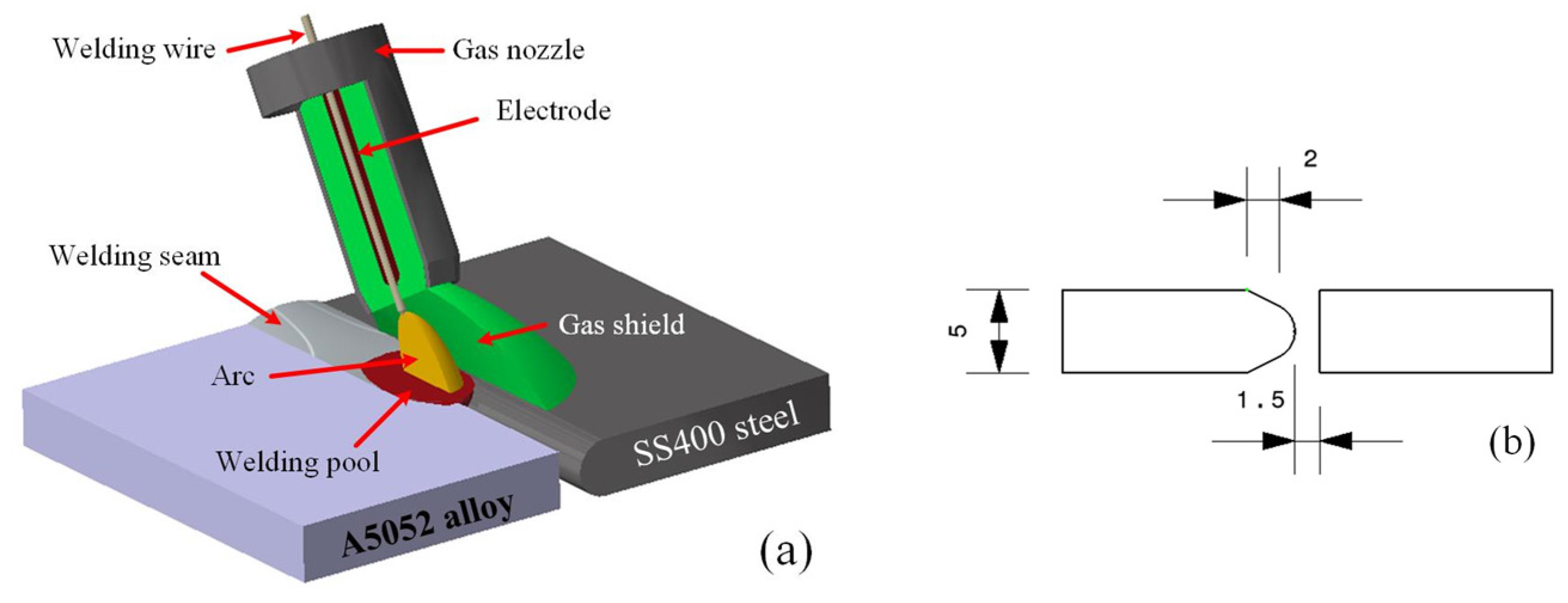
2.2. Experimental Procedure
3. Results and Discussion
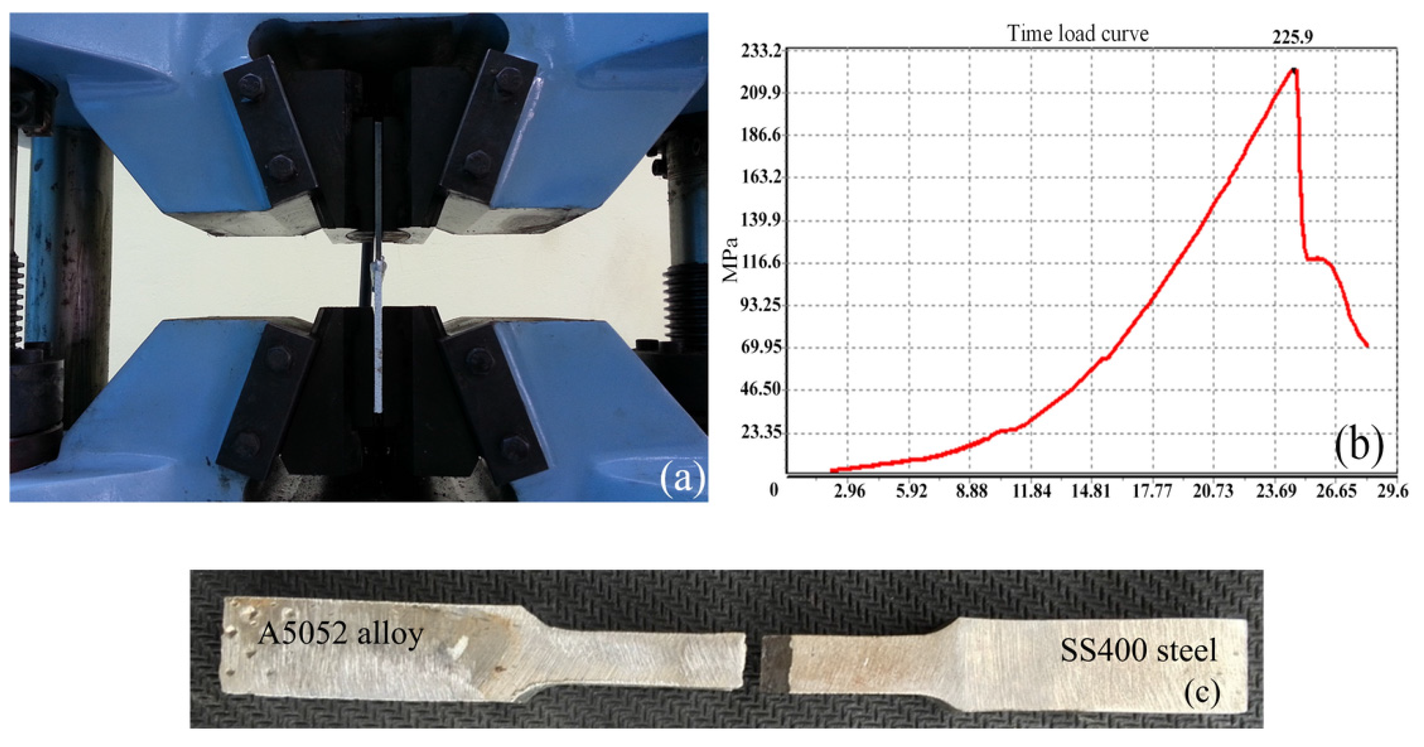
| Specimens | P1 | P2 | P3 | P4 | P5 | P6 | P7 | Average | ER4043 | A5052 |
|---|---|---|---|---|---|---|---|---|---|---|
| Values (MPa) | 206.5 | 203 | 195.5 | 220 | 225.9 | 215 | 193.5 | 208.5 | 165 | 250 |
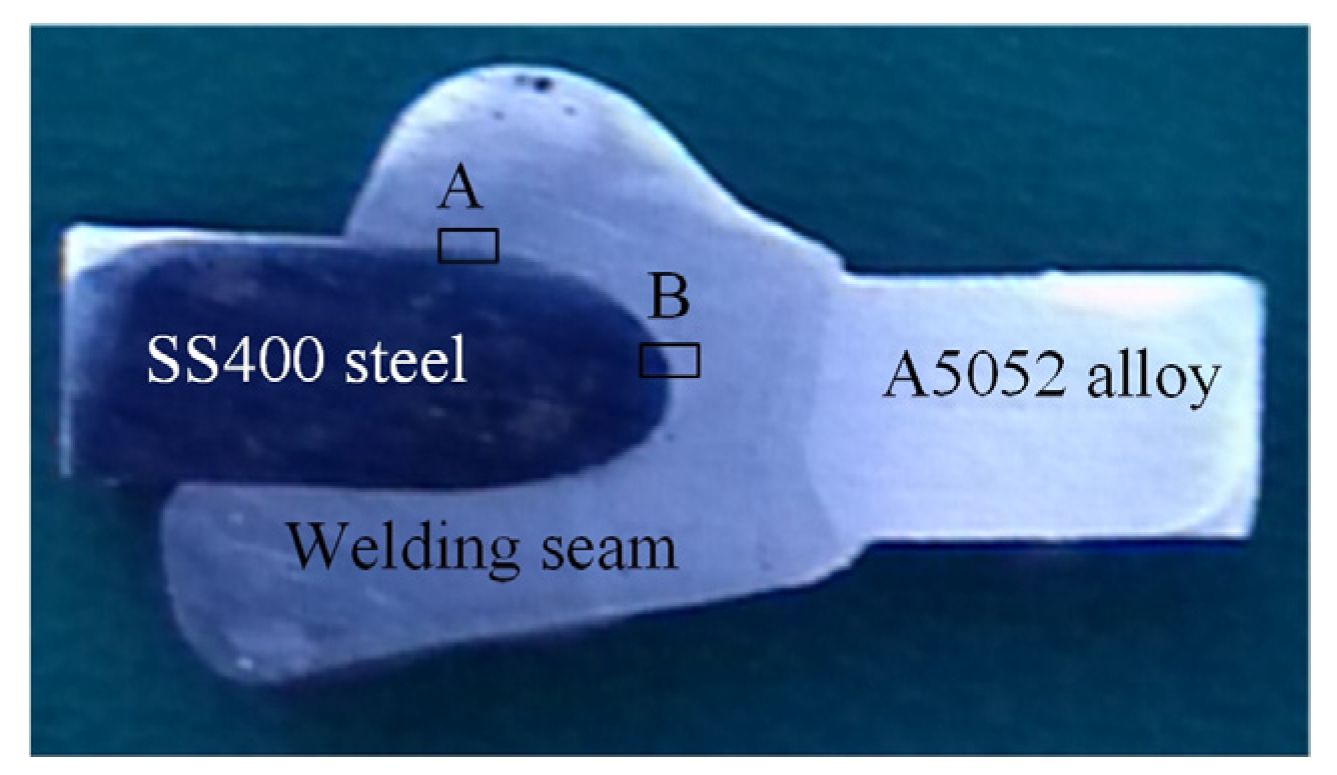
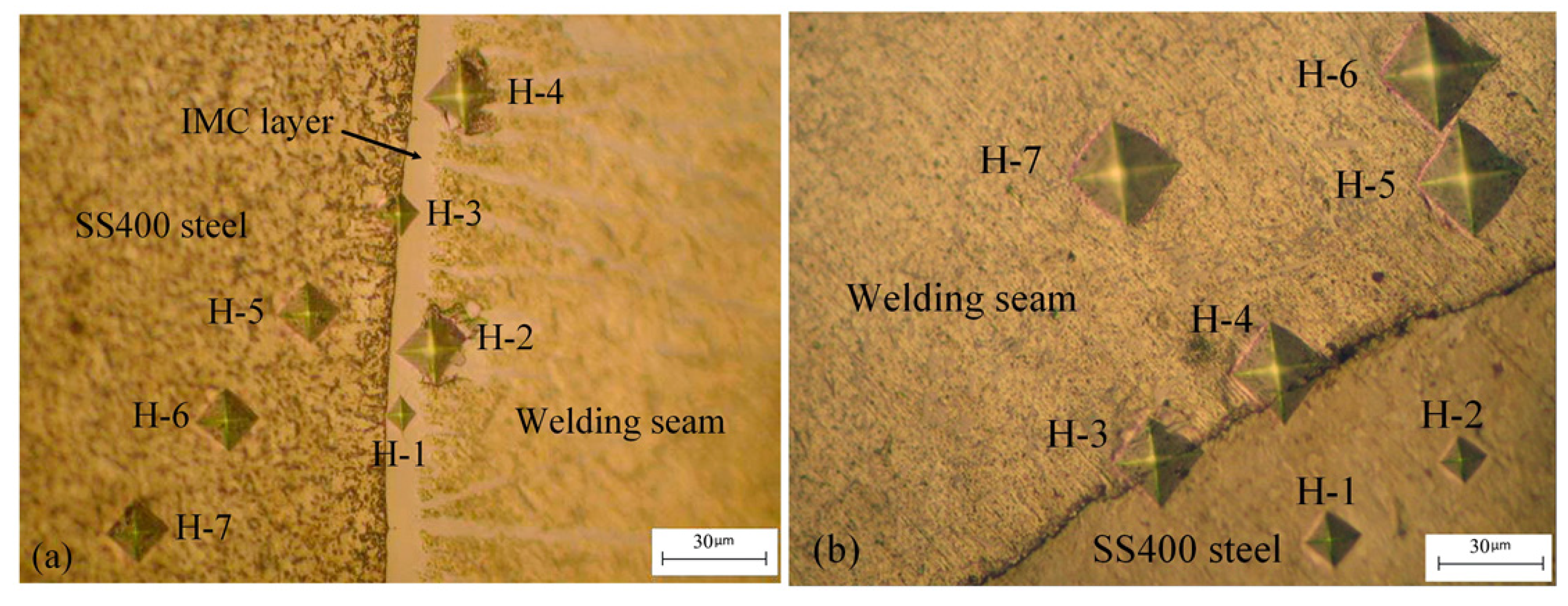
| Specimens | H-1 | H-2 | H-3 | H-4 | H-5 | H-6 | H-7 | Average | ER4043 |
|---|---|---|---|---|---|---|---|---|---|
| IMC layer (HV) | 850 | 209 | 468 | 182 | 240 | 237 | 239 | 346.43 | 61 |
| Without IMC layer (HV) | 287 | 291 | 129 | 118 | 86.2 | 85.3 | 88.3 | 117.85 |


4. Conclusions
- Welding dissimilar metals using the new chamfering method was successful on the front side and the bottom side. Because the SS400 steel had a higher melting temperature, it only melted a bit at the surface; the A5052 alloy had a lower melting temperature, so it melted completely.
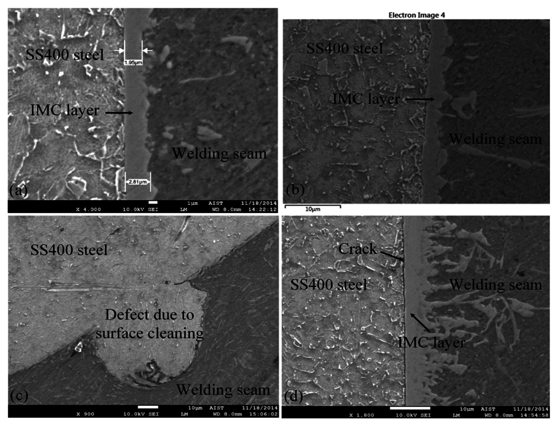
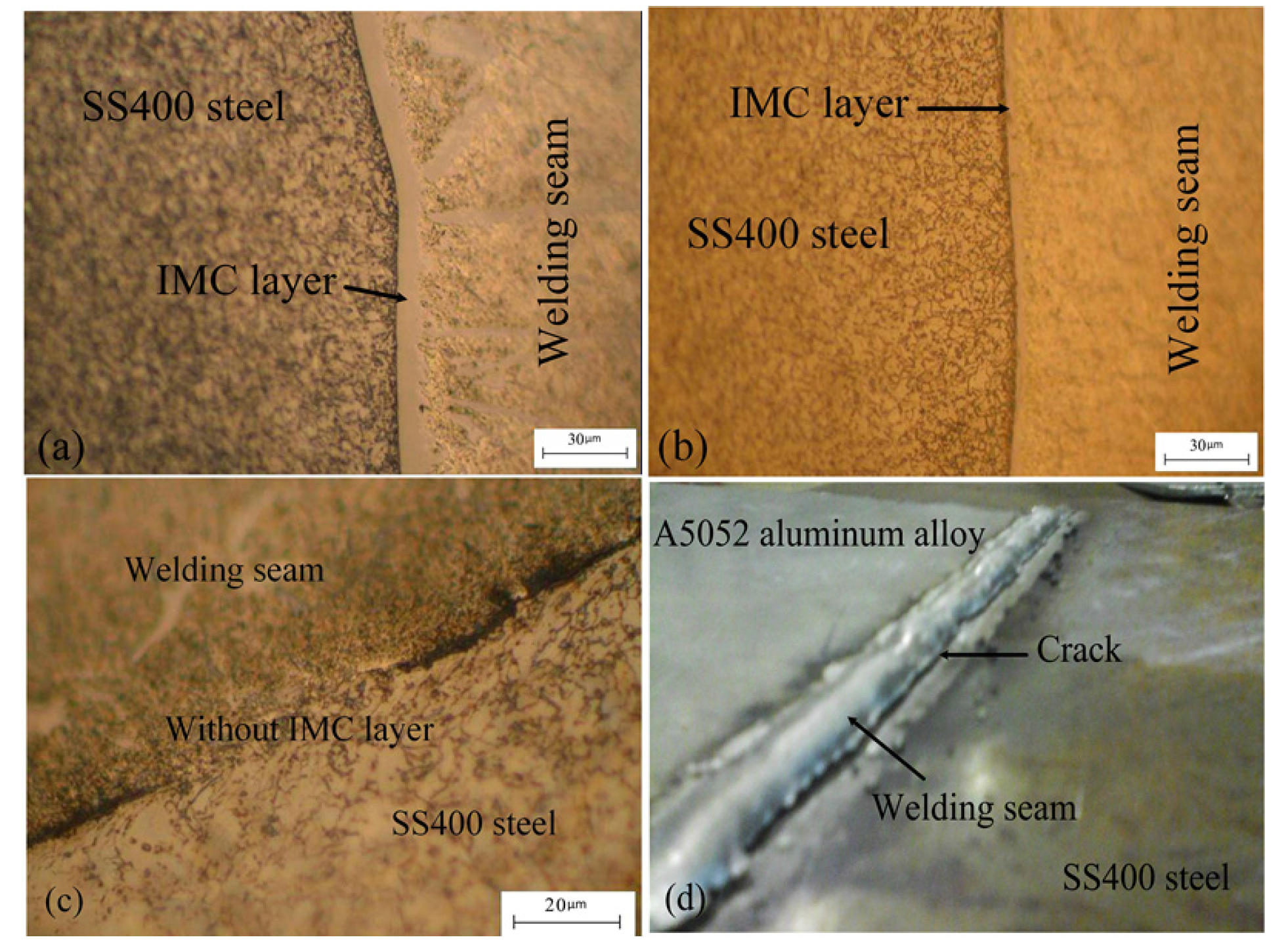
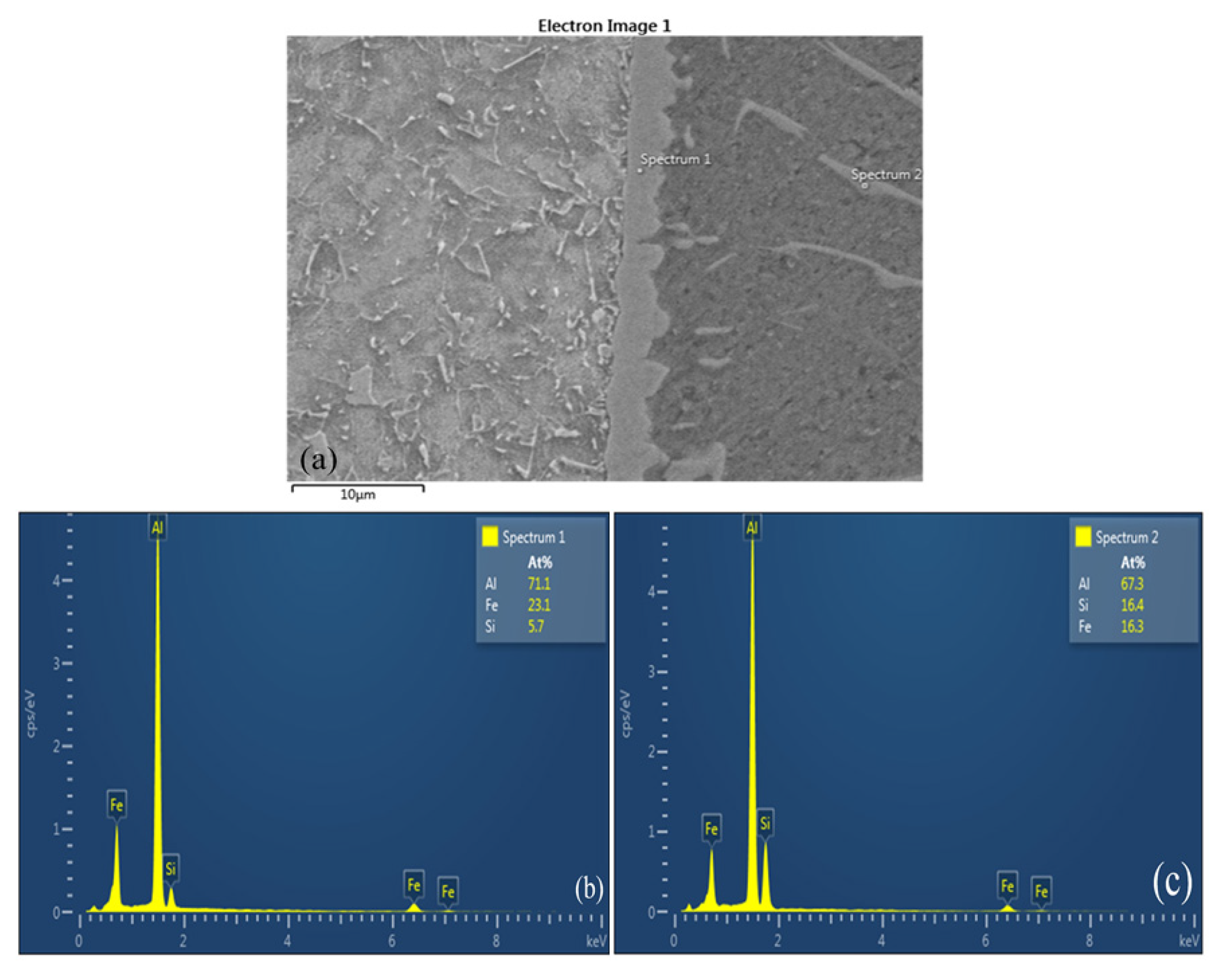
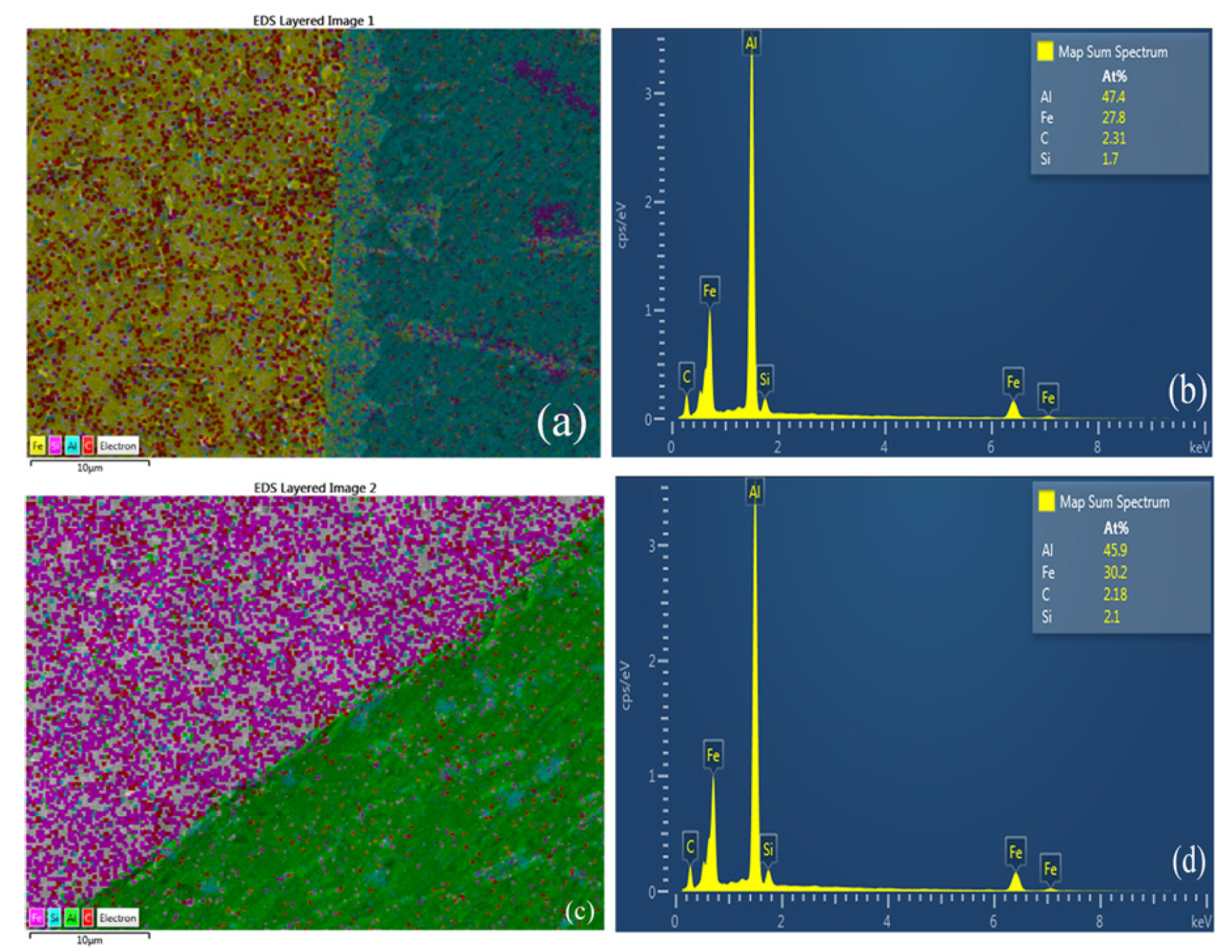
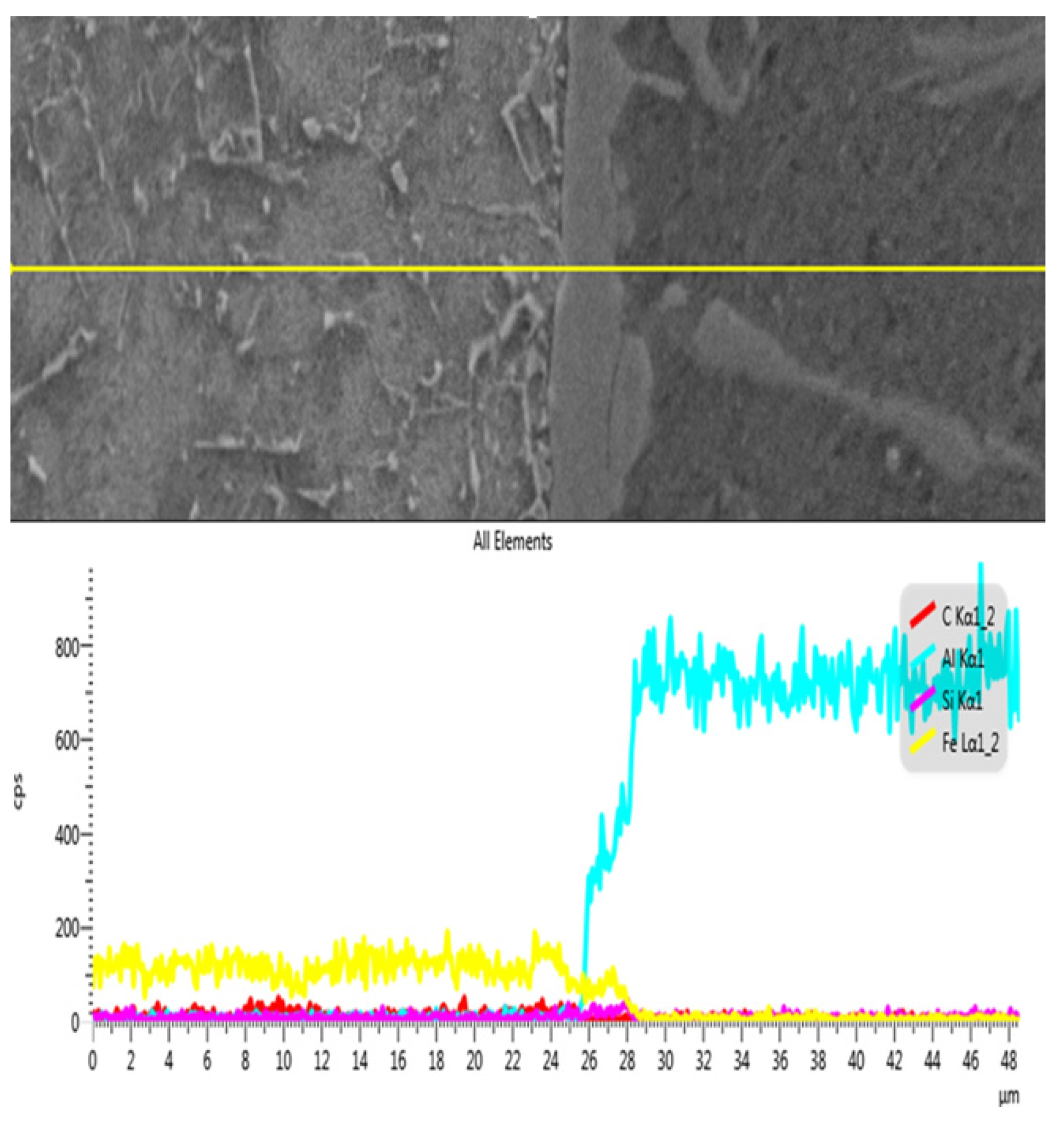
- As the welding was done by hand, the thickness of the intermetallic layer was not uniform, ranging from 1.95–5 μm, and formed on the surface of the steel sheet. Minimizing the thickness of the intermetallic layer improved the quality of the welds. The SEM/EDS analysis showed the metallurgical interaction between the welding seam and SS400 steel.
- The average value of the tensile strength of the specimens was higher than the tensile strength of the welding wire ER4043, at 26.4%, and the average value was equivalent to 85% of the tensile strength of the A5052 aluminum alloy. The average microhardness value at the IMC layer zone and without the IMC layer zone in this research was higher than that of the welding wire ER4043 (56–64 HV), showing that the dynamic load capacity was low and the welds were brittle.
- Cracks, resulting from the use of high power in the welding process, were found between the welding seam and SS400 chamfered steel when the IMC layer was too thick.
Acknowledgments
Author Contributions
Conflicts of Interest
References
- Tu, J.F.; Paleocrassas, A.G. Fatigue crack fusion in thin-sheet aluminum alloys AA7075-T6 using low-speed fiber laser welding. J. Mater. Process. Technol. 2011, 211, 95–102. [Google Scholar] [CrossRef]
- Sierra, G.; Peyre, P.; Deschaux-Beaume, F.; Stuart, D.; Fras, G. Steel to aluminium key-hole laser welding. Mater. Sci. Eng. A 2007, 447, 197–208. [Google Scholar] [CrossRef]
- Ito, K.; Okuda, T.; Ueji, R.; Fujii, H.; Shiga, C. Increase of bending fatigue resistance for tungsten inert gas welded SS400 steel plates using friction stir processing. Mater. Des. 2014, 61, 275–280. [Google Scholar] [CrossRef]
- Shih, J.S.; Tzeng, Y.F.; Lin, Y.F.; Yang, J.B. Multi-objective process optimization of pulsed plasma arc welding SS400 steel pipe with foamed aluminum liner. J. Adv. Mech. Des. Syst. Manuf. 2012, 6, 222–235. [Google Scholar] [CrossRef]
- Dehghani, M.; Amadeh, A.; Akbari Mousavi, S.A.A. Investigations on the effects of friction stir welding parameters on intermetallic and defect formation in joining aluminum alloy to mild steel. Mater. Des. 2013, 49, 433–441. [Google Scholar] [CrossRef]
- Dehghani, M.; Akbari Mousavi, S.A.A.; Amadeh, A. Effects of welding parameters and tool geometry on properties of 3003-H18 aluminum alloy to mild steel friction stir weld. Trans. Nonferrous Met. Soc. China 2013, 23, 1957–1965. [Google Scholar] [CrossRef]
- Jia, L.; Shichun, J.; Yan, S.; Cong, N.; Junke, C.; Genzhe, H. Effects of zinc on the laser welding of an aluminum alloy and galvanized steel. Mater. Des. 2011, 31, 458–465. [Google Scholar] [CrossRef]
- Qiu, R.; Shia, H.; Zhanga, K.; Tua, Y.; Iwamotoc, C.; Satonaka, S. Interfacial characterization of joint between mild steel and aluminum alloy welded by resistance spot welding. Mater. Charact. 2010, 61, 684–688. [Google Scholar] [CrossRef]
- Qiu, R.; Iwamoto, C.; Satonaka, S. Interfacial microstructure and strength of steel/aluminum alloy joints welded by resistance spot welding with cover plate. J. Mater. Process. Technol. 2009, 209, 4186–4193. [Google Scholar] [CrossRef]
- Watanabe, T.; Sakuyama, H.; Yanagisawa, A. Ultrasonic welding between mild steel sheet and Al-Mg alloy sheet. J. Mater. Process. Technol. 2009, 209, 5475–5480. [Google Scholar] [CrossRef]
- Watanabe, A.; Watanabe, T.; Sasaki, T. Ultrasonic welding mild steel sheet to Al-Mg alloy sheet. Adv. Mater. Res. 2010, 89–91, 627–632. [Google Scholar] [CrossRef]
- Yong, Y.; Tong, Z.D.; Cheng, Q.; Wen, Z. Dissimilar friction stir welding between 5052 aluminum alloy and AZ31 magnesium alloy. Trans. Nonferrous Met. Soc. China 2010, 20, s619–s623. [Google Scholar]
- Zhang, D.Q.; Li, J.; Joo, H.G.; Lee, K.Y. Corrosion properties of Nd:YAG laser–GMA hybrid welded AA6061 Al alloy and its microstructure. Corros. Sci. 2009, 51, 1399–1404. [Google Scholar] [CrossRef]
- Gómez de Salazar, J.M.; Barrena, M.I. Dissimilar fusion welding of AA7020/MMC reinforced with Al2O3 particles. Microstructure and mechanical properties. Mater. Sci. Eng. A 2003, 352, 162–168. [Google Scholar] [CrossRef]
- Sun, J.; Yan, Q.; Gao, W.; Huang, J. Investigation of laser welding on butt joints of Al/steel dissimilar materials. Mater. Des. 2015, 83, 120–128. [Google Scholar] [CrossRef]
- Kobayashi, S.; Yakou, T. Control of intermetallic compound layers at interface between steel and aluminum by diffusion-treatment. Mater. Sci. Eng. A 2002, 338, 44–53. [Google Scholar] [CrossRef]
- Yousaf, M.; Iqbal, J.; Ajmal, M. Variables affecting growth and morphology of the intermetallic layer (Fe2Al5). Mater. Charact. 2011, 62, 517–525. [Google Scholar] [CrossRef]
- Song, J.L.; Lin, S.B.; Yang, C.L.; Fan, C.L. Effects of Si additions on intermetallic compound layer of aluminum-steel TIG welding-brazing joint. J. Alloys Compd. 2009, 488, 217–222. [Google Scholar] [CrossRef]
© 2015 by the authors; licensee MDPI, Basel, Switzerland. This article is an open access article distributed under the terms and conditions of the Creative Commons by Attribution (CC-BY) license (http://creativecommons.org/licenses/by/4.0/).
Share and Cite
Nguyen, Q.M.; Huang, S.-C. An Investigation of the Microstructure of an Intermetallic Layer in Welding Aluminum Alloys to Steel by MIG Process. Materials 2015, 8, 8246-8254. https://doi.org/10.3390/ma8125444
Nguyen QM, Huang S-C. An Investigation of the Microstructure of an Intermetallic Layer in Welding Aluminum Alloys to Steel by MIG Process. Materials. 2015; 8(12):8246-8254. https://doi.org/10.3390/ma8125444
Chicago/Turabian StyleNguyen, Quoc Manh, and Shyh-Chour Huang. 2015. "An Investigation of the Microstructure of an Intermetallic Layer in Welding Aluminum Alloys to Steel by MIG Process" Materials 8, no. 12: 8246-8254. https://doi.org/10.3390/ma8125444