Characteristics of the Dye-Sensitized Solar Cells Using TiO2 Nanotubes Treated with TiCl4


Abstract
: The replacement of oxide semiconducting TiO2 nano particles with one dimensional TiO2 nanotubes (TNTs) has been used for improving the electron transport in the dye-sensitized solar cells (DSSCs). Although use of one dimensional structure provides the enhanced photoelectrical performance, it tends to reduce the adsorption of dye on the TiO2 surface due to decrease of surface area. To overcome this problem, we investigate the effects of TiCl4 treatment on DSSCs which were constructed with composite films made of TiO2 nanoparticles and TNTs. To find optimum condition of TNTs concentration in TiO2 composites film, series of DSSCs with different TNTs concentration were made. In this optimum condition (DSSCs with 10 wt% of TNT), the effects of post treatment are compared for different TiCl4 concentrations. The results show that the DSSCs using a TiCl4 (90 mM) post treatment shows a maximum conversion efficiency of 7.83% due to effective electron transport and enhanced adsorption of dye on TiO2 surface.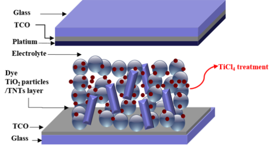
1. Introduction
Since their invention in 1991, dye-sensitized solar cells (DSSCs) have been extensively studied as an alternative to silicon-based solar cells, owing to their simple structure, transparency, flexibility, low production cost, and wide range of application. Despite these advantages, the low efficiency of DSSCs compared to that of silicon-based cells has limited their commercial implementation [1–4]. Consequently, there is a critical need to improve the efficiency of state-of-the-art DSSCs in order to realize next generation solar cells.
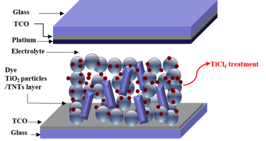
DSSCs are composed of four parts as follows: (1) the electrode film layer (TiO2), covered by a monolayer of dye molecules, that absorbs solar energy; (2) the conductive transparent conductive oxide layer that facilitates charge transfer from the electrode layer; (3) the counter electrode layer made of Pt or C; (4) the redox electrolyte layer for reducing the level of energy supplied from the dye molecules [5,6]. Thus, research efforts to improve the efficiency of DSSCs have primarily been focused on improvements of the each DSSC component [7]. However, due to synergetic effects of its subcomponents, the enhancement of only one component might not be sufficient to improve efficiency of entire cell.
The interconnected TiO2 nanoparticle is widely used as the mesoporous electrode film layer, because it is beneficial for adsorption large amount of dye molecules due to its large surface areas. However, the overall performance of DSSCs can be limited by the electron transport in the nanocrystal boundaries of TiO2 nanoparticles and the electron recombination with the electrolyte during the electron migration process. To avoid this problem, many researchers have reported that one dimensional nanostructures can be used in DSSCs as replacements of nanoparticles to facilitate electron transfer [8–14]. In addition to their unique electron properties, one-dimensional TiO2 nanostructures also function as light scattering materials. Nevertheless, dye adsorption in the one dimensional structure should be sacrificed due to the reduction of surface area.
In this work, we have considered combined strategies to improve the efficiency of DSSCs. We used oxide semiconductors in the form of TiO2 nanotube (TNTs) to improve the electron transport through the film. Though a higher photoelectrical performance was obtained, we believe that further improvements in the photoelectrical performance of DSSCs could be achieved. To overcome reduced dye adsorption in one dimensional structure, we investigated the effects of TiCl4 post treatment on DSSCs, combined with variations in the concentration of TNTs in TiO2 nanoparticle/TNT composites. Consequently, this approach can be used for effectively increasing the dye adsorption of TiO2 films.
2. Experimental Section
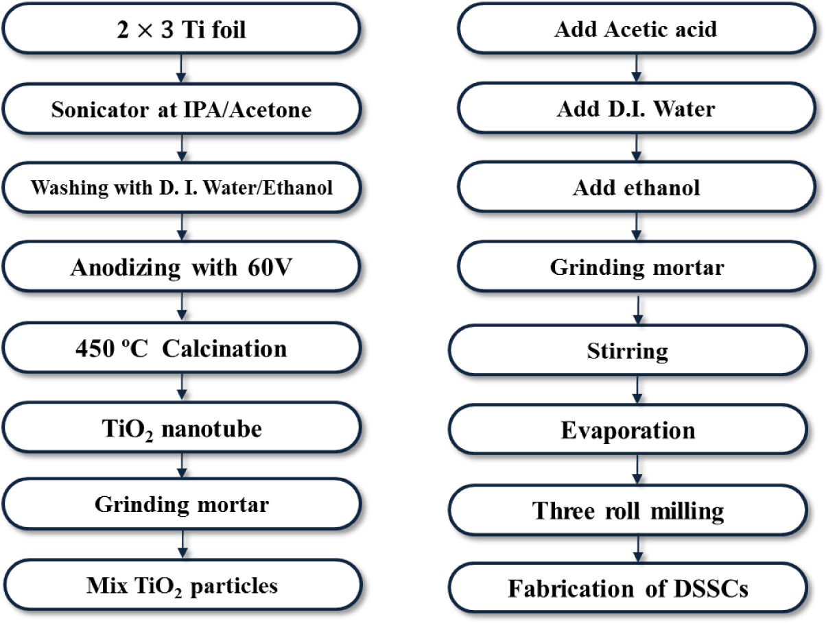
TNTs were prepared by an optimized three step anodization process. Ti foil (0.25 mm thickness, 99.7% purity, Sigma-Aldrich, St. Louis, MO, USA) with an area of 2 cm × 3 cm was degreased by ultrasonic agitation in acetone, isopropanol, and deionized water for 15 min each and then dried with N2 gas. The ethylene glycol electrolyte contained 0.25 wt% NH4F (98%, Sigma-Aldrich, St. Louis, MO, USA) and 2 vol% deionized water. The anodization was performed in a two electrode system where the Ti foil served as the working electrode and a Pt plate as the counter electrode. Anodization was conducted at room temperature at a constant voltage of 60 V, as shown in Figure 1. In order to obtain powders, the fabricated TNTs had to be detached from the Ti sheet in a H2O2 solution. The anodic oxidation was repeated many times to obtain the required amount of TNT powder. To achieve TNT powder of the desired crystallinity, the powder was calcined in air at 450 °C for 3 h then the samples were milled with a mortar and pestle. Following this, the TiO2 nanoparticles (Anatase 99.9%, Sigma-Aldrich, St. Louis, MO, USA), and the TNT powder were mixed in various ratios (5–20 wt%) and ground in a mortar.
In addition, TiO2 paste was prepared by combining TiO2 nanoparticles with TNT powder. The prepared TiO2 paste was coated onto FTO-glass (Fluorine-doped tin oxide coating glass) by a doctor blade. The TiO2 coated substrate was calcined at 250 °C for 15 min and then at 450 °C for 15 min to promote crystal growth and remove organic constituents.
TiO2 films were dipped for 30 min in a 30–120 mM TiCl4 aqueous solution at 70 °C which was prepared by adding titanium tetrachloride (Sigma-Aldrich, St. Louis, MO, USA) to precooled distilled water in an ice bath. Following the post treatment, the TiO2 film was annealed at 450 °C for 15 min.
A Pt catalyst electrode was prepared by mixing H2PtCl6 (5 mM, Sigma-Aldrich, St. Louis, MO, USA) in isopropyl alcohol with an ultrasonic treatment. A counter electrode, which facilitates the redox reaction of the electrolyte, was fabricated by spin coating the H2PtCl6 solution at 1000 rpm for 30 s, and annealed at 450 °C for 30 min.
The dye solution to be adsorbed on the electrode films was prepared by mixing 0.5 mM Ru-dye (N719, Solaronix, Rue de I`Ouriette, Aubonne, Switzerland) with ethanol. To facilitate the adsorption of the dye molecules, the prepared TiO2 electrode films were placed in the dye solution in darkness for 24 h.
Finally, the DSSC was fabricated by sandwiching the prepared electrode film and counter electrode at 120 °C for 10 min using a hot melt sealant (60 °C). The electrolyte (I−/I3−) was injected between the two electrodes with the inlet then sealed by a cover glass.
The phase of the TNTs obtained by anodization was examined by X-ray diffraction (XRD), using a Rigaku D/max-2200 diffractometer (Rigaku, Tokyo, Japan) with a CuKα radiation source. The morphology of the prepared TiO2 films was investigated by field-emission scanning electron microscopy (FE-SEM, Hitachi S-4700, Tokyo, Japan) and the optical transmittance of the prepared TiO2 electrode films was measured using a UV-Vis spectrometer (Perkin Elmer Lambda 750, Waltham, MA, USA). The conversion efficiency and electrochemical impedance spectroscopy (EIS, Mcscience K3400, Suwonn-si, Gyeonggi-do, Korea) of the fabricated DSSCs were measured using an I–V solar simulator (McScience K3000, Suwonn-si, Gyeonggi-do, Korea). The active area of the resulting cell exposed to light was approximately 0.25 cm2 (0.5 cm × 0.5 cm).
3. Results and Discussion
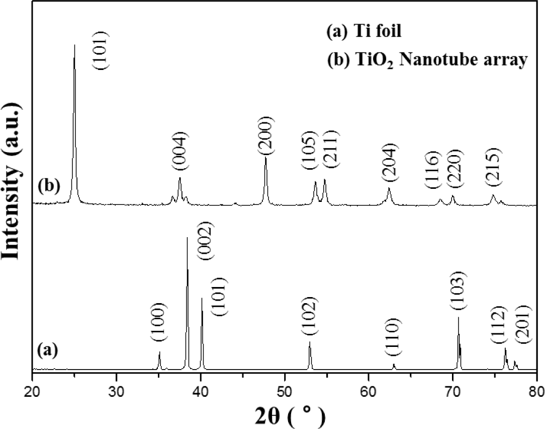
Figure 2 shows the XRD pattern of the Ti foil (JCPDS No. 44-1294) and of the TNT array by calcination at 450 °C. After anodization, the TNT array peeled off from the Ti substrate and was analyzed and tested by XRD. The diffraction peaks of TNT array are in good agreement with the standard JCPDS cards of anatase TiO2 (No. 21-1272). The XRD pattern of the TNT array shows (101), (004), (200), (105), (211), (204), (116), (220) and (215) anatase peaks.
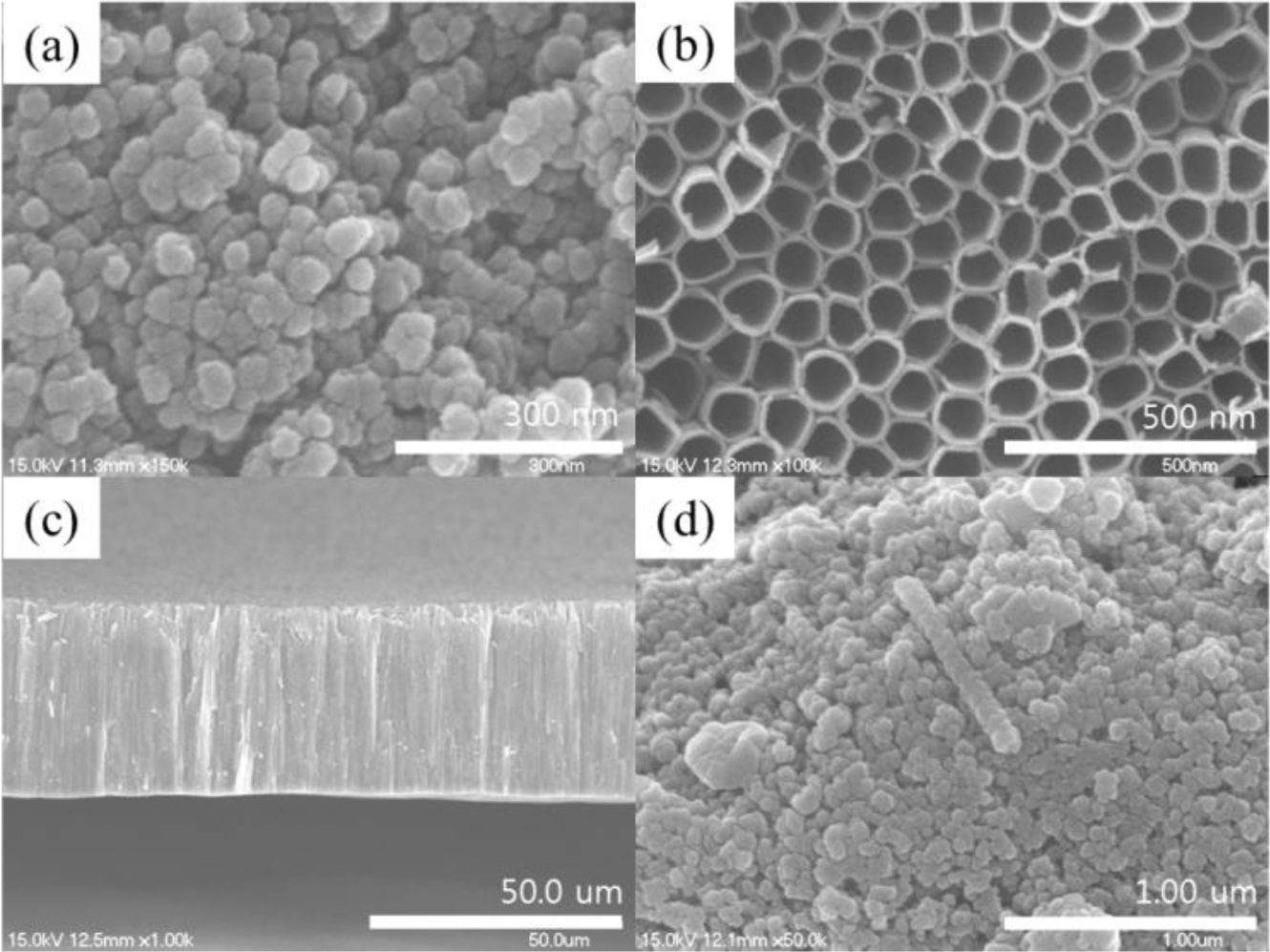
Figure 3a shows the SEM images of TiO2 nanoparticles. The TiO2 particle size is about 20–30 nm. Figure 3b indicates that the TNT diameter is about 120 nm, and the TNT surface is uniform. Additionally, for anodic oxidation at present conditions, the TNTs can come to a length of 40–45 μm as shown in Figure 3c. It is obvious that the TiO2 nanoparticles, TNTs, and the substrate are well linked, which is helpful for the quick electron transportation in the film. Figure 3d shows the length of TNTs in a TiO2 nanoparticle/TNT mixture to be approximately 1 μm.
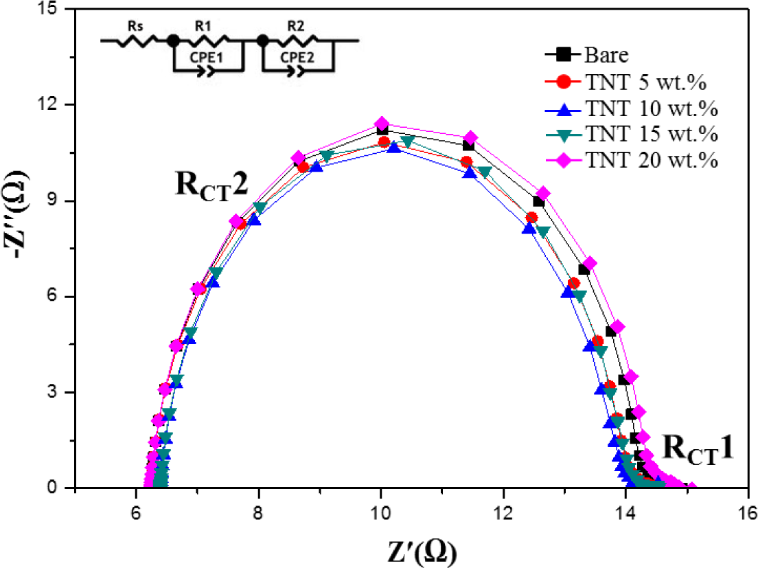
Figure 4 shows the electrochemical impedance spectroscopy (EIS) analysis of TiO2 nanoparticles/TNTs obtained at various weight ratios, which provides information about the electron transport and recombination in DSSCs. Two typical semicircles are observed in Nyquist plots, the small semicircular in the high frequency ranges and the large semicircular in the low frequency ranges correspond to the resistances of Pt/electrolyte interface and electrolyte/dye/TiO2 interface. The small semicircle is fit to a charge-transfer resistance (RCT1) and constant phase, while the large semicircle is fit to a transfer resistance (RCT2) and constant phase. As RCT1 is not affected by the use of TiO2 nanoparticles/TNTs, we focused on the variations in RCT2. The first semicircle is a minimum for the TNTs (10 wt%), which is related to charge-transfer resistance of the FTO/TiO2 and TiO2/electrolyte interfaces (RCT2). The observed decrease in RCT2 of TNTs (10 wt%) indicates a reduction in electron recombination and enhancement in the efficiency of electron transport. However, in the case of the TNTs (15 wt%), RCT2 increased with increasing of TNTs (15 wt%), due to the increase of trap sites which obstructs the movement of electrons from the TiO2 film to the photoelectrode [15–18].
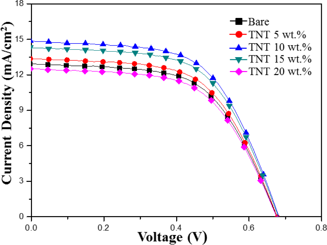
Figure 5 shows the current-voltage photovoltaic performance of DSSCs composed of bare TiO2 nanoparticles and TNTs (5–20 wt%) under AM 1.5 illumination (100 mW/cm2). Table 1 summarizes the efficiency, fill factor, open circuit voltage, and integral photocurrent for the corresponding solar cells. DSSC with 10 wt% of composite TiO2 nanoparticles/TNTs film exhibited the highest light-to-electric energy conversion efficiency of 5.95%, short-circuit current density of 14.86 mA/cm2, open-circuit voltage of 0.68 V, and fill factor of 58.79%. These results indicate that the JSC value increased significantly with the addition of the TNTs. However, the addition of TNTs had little influence on the open circuit voltage (VOC) and the fill factor (FF). The observed increase in JSC could be attributed to the increased electron lifetime in the one-dimensional electrode on the composite TiO2 nanoparticles/TNTs film.
DSSC with TNT (10 wt%) were referred as “Bare” condition (i.e., internal reference) in the following measurements to investigate effect of TiCl4 post treatment on DSSCs.
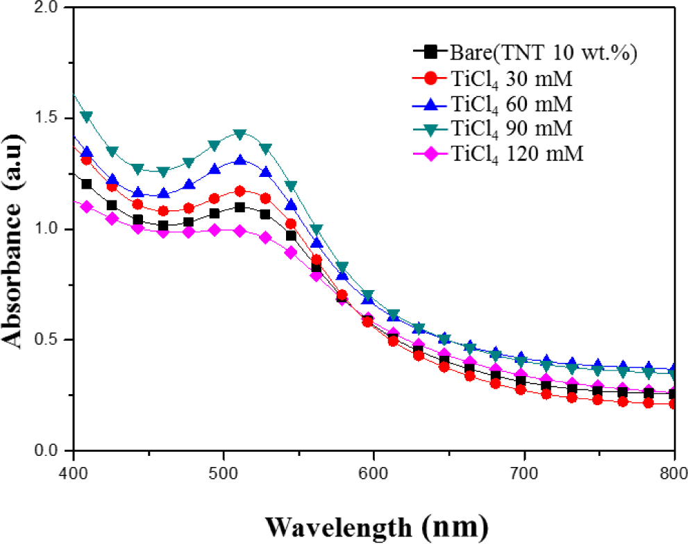
Figure 6 shows the absorption spectrum of N-719 dye in the 400–800 nm wavelength range in the various TiCl4 post treatment (30–120 mM) TiO2 films. At the wavelength 400–500 nm, the sample treated with a TiCl4 concentration of 90 mM has the highest absorbance. It is reasonable that the TiCl4 post treatment electrode provides more sites for dye absorption than the Bare (TNT 10 wt%), leading to a higher light harvesting and Jsc as expected.
According to Lambert-Beer’s law, higher absorbance means a higher dye concentration. A suitable amount of TiCl4 in the film could provide a large surface area for dye adsorption. It is reported that small TiO2 particles are formed on the surface of TiO2 films by TiCl4 post treatment and the surface area and the amount of dye adsorption are increased [19–23]. It is well known that the photocurrent of DSSCs is correlated directly with the number of dye molecules. Therefore, the increase of adsorbed dye molecules results in the increase of incident light being harvested and consequently a larger photocurrent.
In case of TiCl4 post treatment with high concentration (120 mM), the absorbance was decrease. The post treatment with the high concentrations can lead the decrease of dye absorption of TiO2 film due to the reduction of the film porosity by an increase of the nucleation in the nanoparticles. So, the inefficient charge-transfer paths increase the recombination rate of electrons, as a result, the photocurrent density and conversion efficiency can be decreased [24,25].
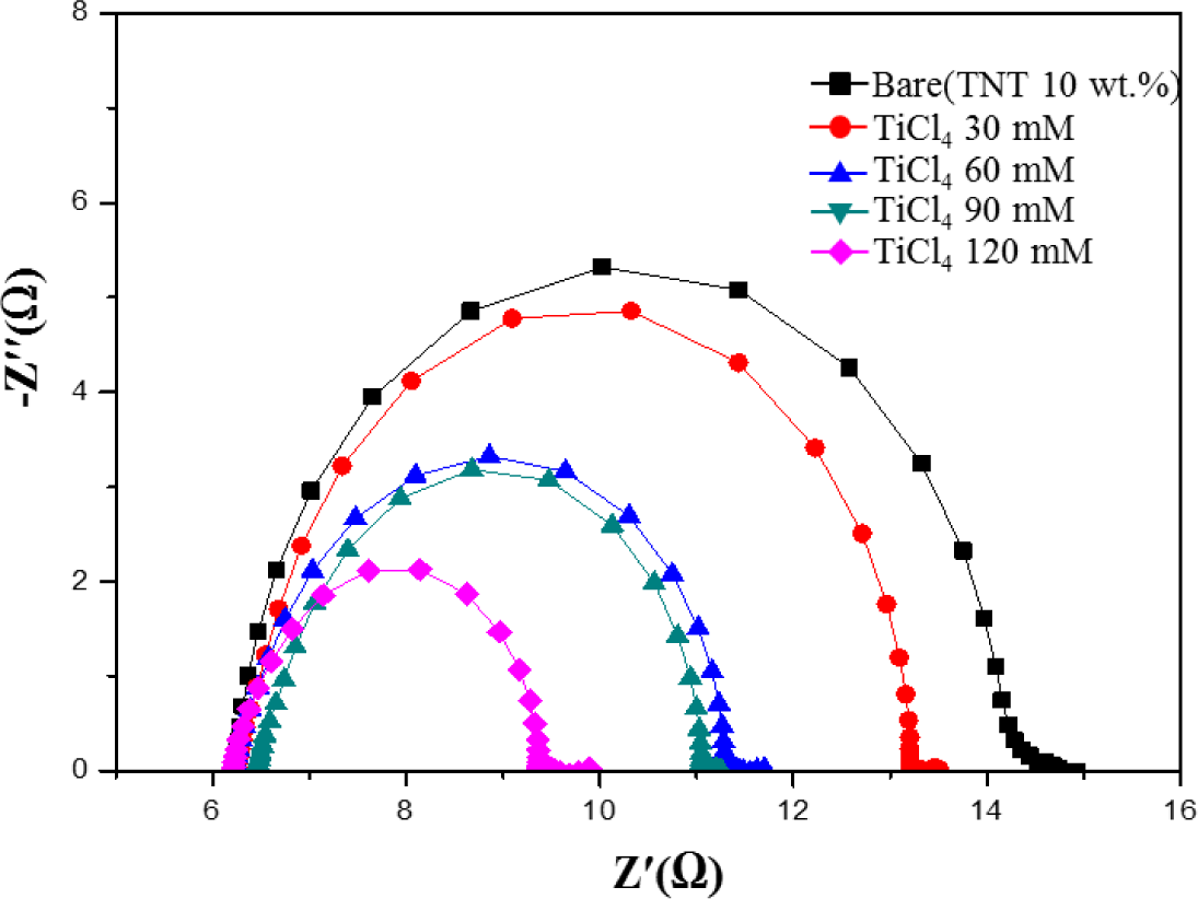
Figure 7 shows electrochemical impedance spectroscopy (EIS) Nyquist plots of DSSCs with a TiCl4 post treatment. EIS is a useful method for the analysis of charge-transport processes and internal resistances [26]. As shown in Figure 7, there is a decrease in the charge-transfer resistance (RCT) upon increasing the TiCl4 ratio from 30 mM to 120 mM. This increases the number of injected electrons into the TiO2 film, improves the electrical conductivity, and reduces the charge recombination at the TiO2/dye/electrolyte interface [27,28]. RCT becomes smaller when the TiCl4 ratio increases. The reduction of RCT means there is a decrease in the recombination rate and indicates fast electron-transfer processes in the DSSCs. The efficient charge-transfer paths decrease the recombination rate of electrons with I3− or the oxidizing dye, resulting in a high photocurrent density and conversion efficiency [24].
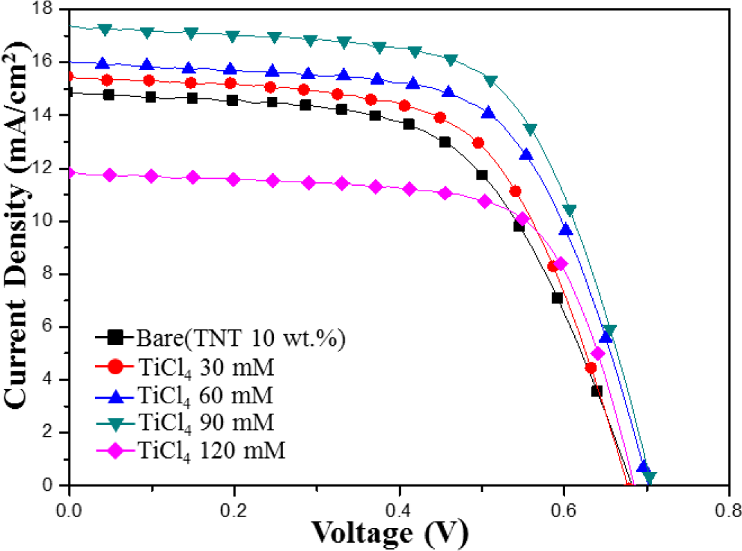
Figure 8 shows the I–V characteristics of the TiO2 film with the various TiCl4-concentration post treatments. Two of the most important parameters for a solar cell are its photoelectric conversion efficiency and the fill factor (FF). When the I–V curves approach a square shape, the FF is higher. In addition, solar cells with a high FF have a stable output voltage and current compared to the cell with the same VOC and JSC, and they produce more power. The photovoltaic properties of all post treated films are summarized in Table 2. JSC increases with the amount of TiCl4 until the TiCl4 concentration is 90 mM, beyond this limitation, JSC decreases. JSC increase was improved due to the increase of dye adsorption and it could be explained by the enhanced loading of dye molecules on TiO2 films, which resulted in the improvement of JSC, and a decrease in the charge-transfer resistance at interfaces. In the case of the TiCl4 (120 mM), decrease of JSC was result in low absorption of dye from the TiO2 film to the photoelectrode.
The FF increased from 58% to 68% after TiCl4 post treatment. With optimum post treatment conditions, the DSSCs fabricated on the TiCl4 post treatment substrate showed an efficiency value of 7.83% due to an increased photocurrent density and fill factor.
4. Conclusions
In this work, the improvement of performance on DSSCs using a TiCl4 post-treatment on the TiO2 films is proposed. The DSSCs were constructed with TiO2 films made from TiO2 nanoparticles and TNTs which were fabricated from an anodization process. Without post-treatment, DSSCs with light-to-electric energy conversion efficiency of 5.95% was achieved under a simulated solar light irradiation of 100 mW·cm2 (AM 1.5). The DSSCs based on a TiO2 nanoparticles/TiO2 nanotube composite showed a better photovoltaic performance (higher JSC) than the cell purely made of TiO2 nanoparticles. It was found that the conversion efficiency of DSSCs was highly affected by the properties of TNTs. The effect of a TiCl4 post-treatment on the TiO2 films was investigated using different the mole ratio of TiCl4. DSSCs using TNTs and a TiCl4 post treatment were measured to have a maximum conversion efficiency of 7.83% due to effective electron transport. Using TNTs (10 wt%) and a TiCl4 (90 mM) post treatment process was found to be an effective method to improve the efficiency of TiO2 nanoparticle based DSSCs.
Acknowledgments
This work was supported by the Human Resources Development program (No. 20124030200010) of the Korea Institute of Energy Technology Evaluation and Planning (KETEP) grant funded by the Korea government Ministry of Trade, Industry and Energy. This work was also supported by the National Research Foundation of Korea (NRF) Grant funded by the Korean Government (MEST) (No. 2012R1A1A2044472).
Author Contributions
The first author (Jun Hyuk Yang) carried out the laboratory test, the co-author (Kyung Hwan Kim; Chung Wung Bark) took charge of the small-scale laboratory measurement analysis, and the corresponding author (Hyung Wook Choi) have controlled the whole project.
Conflicts of Interest
The authors declare no conflict of interest.
References
- O’Regan, B.; Grätzel, M. A low-cost, high-efficiency solar cell based on dye-sensitized colloidal TiO2 films. Nature 1991, 353, 737–740. [Google Scholar]
- Lee, B.; Kim, J. Enhanced efficiency of dye-sensitized solar cells by UV–O3 treatment of TiO2 layer. Curr. Appl. Phys 2009, 9, 404–408. [Google Scholar]
- O’Regan, B.; Grätzel, M. Optical electrochemistry I: Steady-state spectroscopy of conduction-band electrons in a metal oxide semiconductor electrode. Chem. Phys. Lett 1991, 183, 89–93. [Google Scholar]
- Durr, M.; Schmid, A.; Obermaier, M.; Rosselli, S.; Yasuda, A.; Nelles, G. Low-temperature fabrication of dye-sensitized solar cells by transfer of composite porous layers. Nature 2005, 4, 607–611. [Google Scholar]
- Matsui, H.; Okada, K.; Kawashima, T.; Ezure, T.; Tanabe, N.; Kawano, R.; Watanabe, M. Application of an ionic liquid-based electrolyte to a 100 mm × 100 mm sized dye-sensitized solar cell. J. Photochem. Photobiol. A Chem 2004, 164, 129–135. [Google Scholar]
- Kim, S.S.; Nah, Y.C.; Noh, Y.Y.; Jo, J.; Kim, D.Y. Electrodeposited Pt for cost-efficient and flexible dye-sensitized solar cells. Electrochim. Acta 2006, 51, 3814–3819. [Google Scholar]
- Robertson, N. Optimizing Dyes for Dye-Sensitized Solar Cells. Int. Ed 2006, 45, 2339–2345. [Google Scholar]
- Xu, C.; Shin, P.H.; Cao, L.; Wu, J.; Gao, D. Ordered TiO2 Nanotube Arrays on Transparent Conductive Oxide for Dye-Sensitized Solar Cells. Chem. Mater 2010, 22, 143–148. [Google Scholar]
- Stergiopoulos, T.; Valota, A.; Likodimos, V.; Speliotis, T.; Niarchos, D.; Skeldon, P.; Thompson, G.E.; Falaras, P. Dye-sensitization of self-assembled titania nanotubes prepared by galvanostatic anodization of Ti sputtered on conductive glass. Nanotechnology 2009, 20. [Google Scholar] [CrossRef]
- Crossland, E.J.W.; Nedelcu, M.; Ducati, C.; Ludwigs, S.; Hillmyer, M.A.; Steiner, U.; Snaith, H.J. Block Copolymer Morphologies in Dye-Sensitized Solar Cells: Probing the Photovoltaic Structure−Function Relation. Nano Lett 2009, 9, 2813–2819. [Google Scholar]
- Kang, T.S.; Smith, A.P.; Taylor, B.E.; Durstock, M.F. Fabrication of Highly-Ordered TiO2 Nanotube Arrays and Their Use in Dye-Sensitized Solar Cells. Nano Lett 2009, 9, 601–606. [Google Scholar]
- Foong, T.R.B.; Shen, Y.; Hu, X.; Sellinger, A. Template-Directed Liquid ALD Growth of TiO2 Nanotube Arrays: Properties and Potential in Photovoltaic Devices. Funct. Mater 2010, 20, 1390–1396. [Google Scholar]
- Yoon, J.H.; Jang, S.R.; Vittal, R.; Lee, J.; Kim, K.J. TiO2 nanorods as additive to TiO2 film for improvement in the performance of dye-sensitized solar cells. J. Photochem. Photobiol. A Chem 2006, 180, 184–188. [Google Scholar]
- Kang, S.H.; Choi, S.H.; Kang, M.S.; Kim, J.Y.; Kim, H.S.; Hyeon, T.; Sung, Y.E. Nanorod-Based Dye-Sensitized Solar Cells with Improved Charge Collection Efficiency. Adv. Mater 2008, 20, 54–58. [Google Scholar]
- Pan, K.; Dong, Y.; Tian, C.; Zhou, W.; Tian, G.; Zhao, B.; Fu, H. TiO2-B narrow nanobelt/TiO2 nanoparticle composite photoelectrode for dye-sensitized solar cells. Electrochim. Acia 2009, 54, 7350–7356. [Google Scholar]
- Mikroyannidis, J.A.; Strlianakis, M.M.; Roy, M.S.; Suresh, P.; Sharma, G.D. Synthesis, photophysics of two new perylene bisimides and their photovoltaic performances in quasi solid state dye sensitized solar cells. J. Power Sources 2009, 194, 1171–1179. [Google Scholar]
- Bay, L.; West, K.; Jensen, B.W.; Jacobsen, T. Electrochemical reaction rates in a dye-sensitised solar cell—the iodide/tri-iodide redox system. Sol. Energy Mater. Sol. Cells 2006, 90, 341–351. [Google Scholar]
- Lin, L.Y.; Lee, C.P.; Vittal, R.; Ho, K.C. Selective conditions for the fabrication of a flexible dye-sensitized solar cell with Ti/TiO2 photoanode. J. Power Sources 2010, 195, 4344–4349. [Google Scholar]
- Lee, S.H.; Chae, S.Y.; Hwang, Y.J.; Koo, K.-K.; Joo, O.-S. Influence of TiO2 nanotube morphology and TiCl4 treatment on the charge transfer in dye-sensitized solar cells. Appl. Phys. A Mater. Sci. Process 2013, 112, 733–737. [Google Scholar]
- Meen, T.-H.; Jhuo, Y.-T.; Chao, S.-M.; Lin, N.-Y.; Ji, L.-W.; Tsai, J.-K.; Wu, T.-C.; Chen, W.-R.; Water, W.; Huang, C.-J. Effect of TiO2 nanotubes with TiCl4 treatment on the photoelectrode of dye-sensitized solar cells. Nanoscale Res. Lett 2012, 7, 1–5. [Google Scholar]
- Sommeling, P.M.; O’Regan, B.C.; Haswell, R.R.; Smit, H.J.P.; Bakker, N.J.; Smits, J.J.T.; Kroon, J.M.; van Roosmalen, J.A.M. Influence of a TiCl4 post-treatment on nanocrystalline TiO2 films in dye-sensitized solar cells. J. Phys. Chem. B 2006, 110, 19191–19197. [Google Scholar]
- Park, N.-G.; Schlichthorl, G.; van de Lagemaat, J.; Cheong, H.M.; Mascarenhas, A.; Frank, A.J. Dye-sensitized TiO2 solar cells: Structural and photoelectrochemical characterization of nanocrystalline electrodes formed from the hydrolysis of TiCl4. J. Phys. Chem. B 1999, 103, 3308–3314. [Google Scholar]
- Barbe, C.J.; Arendse, F.; Comte, P.; Jirousek, M.; Lenzmann, F.; Shklover, V.; Grätzel, M. Nanocrystalline titanium oxide electrodes for photovoltaic applications. J. Am. Ceram. Soc 1997, 80, 3157–3171. [Google Scholar]
- Zhong, M.; Shi, J.; Zhang, W.; Han, H.; Li, C. Charge recombination reduction in dye-sensitized solar cells by depositing ultrapure TiO2 nanoparticles on “inert” BaTiO3 films. Mater. Sci. Eng. B 2011, 176, 1115–1122. [Google Scholar]
- Xu, W.; Dai, S.; Hu, L.; Zhang, C.; Xiao, S.; Luo, X.; Jing, W.; Wang, K. Influence of Different Surface Modifications on the Photovoltaic Performance and Dark Current of Dye-Sensitized Solar Cells. Plasma Sci. Technol 2007, 9. [Google Scholar] [CrossRef]
- Yang, C.C.; Zhang, H.Q.; Zheng, Y.R. DSSC with a novel Pt counter electrodes using pulsed electroplating techniques. Curr. Appl. Phys 2011, 11, S147–S153. [Google Scholar]
- Fabregat-Santiago, F.; Bisquert, J.; Palomares, E.; Otero, L.; Kuang, D.; Zakeeruddin, S.M.; Grätzel, M. Correlation between Photovoltaic Performance and Impedance Spectroscopy of Dye-Sensitized Solar Cells Based on Ionic Liquids. J. Phys. Chem. C 2007, 111, 6550–6560. [Google Scholar]
- Kern, R.; Sastrawan, R.; Ferber, J.; Stangl, R. Modeling and interpretation of electrical impedance spectra of dye solar cells operated under open-circuit conditions. J. Luther Electrochim. Acta 2002, 47, 4213–4225. [Google Scholar]


| Sample | VOC (V) | JSC (mA/cm2) | FF (%) | Efficiency (η%) |
|---|---|---|---|---|
| Bare | 0.67 | 12.93 | 58.43 | 5.11 |
| TNT 5 wt% | 0.67 | 13.37 | 58.56 | 5.30 |
| TNT 10 wt% | 0.68 | 14.86 | 58.79 | 5.95 |
| TNT 15 wt% | 0.68 | 14.31 | 58.71 | 5.71 |
| TNT 20 wt% | 0.67 | 12.52 | 58.25 | 4.92 |
| Sample | VOC (V) | JSC (mA/cm2) | FF (%) | Efficiency (η%) |
|---|---|---|---|---|
| Bare (TNT 10 wt% | 0.68 | 14.86 | 58.79 | 5.95 |
| TiCl4 30 mM | 0.67 | 15.45 | 61.37 | 6.42 |
| TiCl4 60 mM | 0.70 | 16.02 | 63.75 | 7.16 |
| TiCl4 90 mM | 0.70 | 17.37 | 63.84 | 7.83 |
| TiCl4 120 mM | 0.68 | 11.83 | 68.53 | 5.55 |
© 2014 by the authors; licensee MDPI, Basel, Switzerland This article is an open access article distributed under the terms and conditions of the Creative Commons Attribution license (http://creativecommons.org/licenses/by/3.0/).
Share and Cite
Yang, J.H.; Bark, C.W.; Kim, K.H.; Choi, H.W. Characteristics of the Dye-Sensitized Solar Cells Using TiO2 Nanotubes Treated with TiCl4. Materials 2014, 7, 3522-3532. https://doi.org/10.3390/ma7053522
Yang JH, Bark CW, Kim KH, Choi HW. Characteristics of the Dye-Sensitized Solar Cells Using TiO2 Nanotubes Treated with TiCl4. Materials. 2014; 7(5):3522-3532. https://doi.org/10.3390/ma7053522
Chicago/Turabian StyleYang, Jun Hyuk, Chung Wung Bark, Kyung Hwan Kim, and Hyung Wook Choi. 2014. "Characteristics of the Dye-Sensitized Solar Cells Using TiO2 Nanotubes Treated with TiCl4" Materials 7, no. 5: 3522-3532. https://doi.org/10.3390/ma7053522