A Near-Zero Refractive Index Meta-Surface Structure for Antenna Performance Improvement

Abstract
:1. Introduction
2. Design Specifications
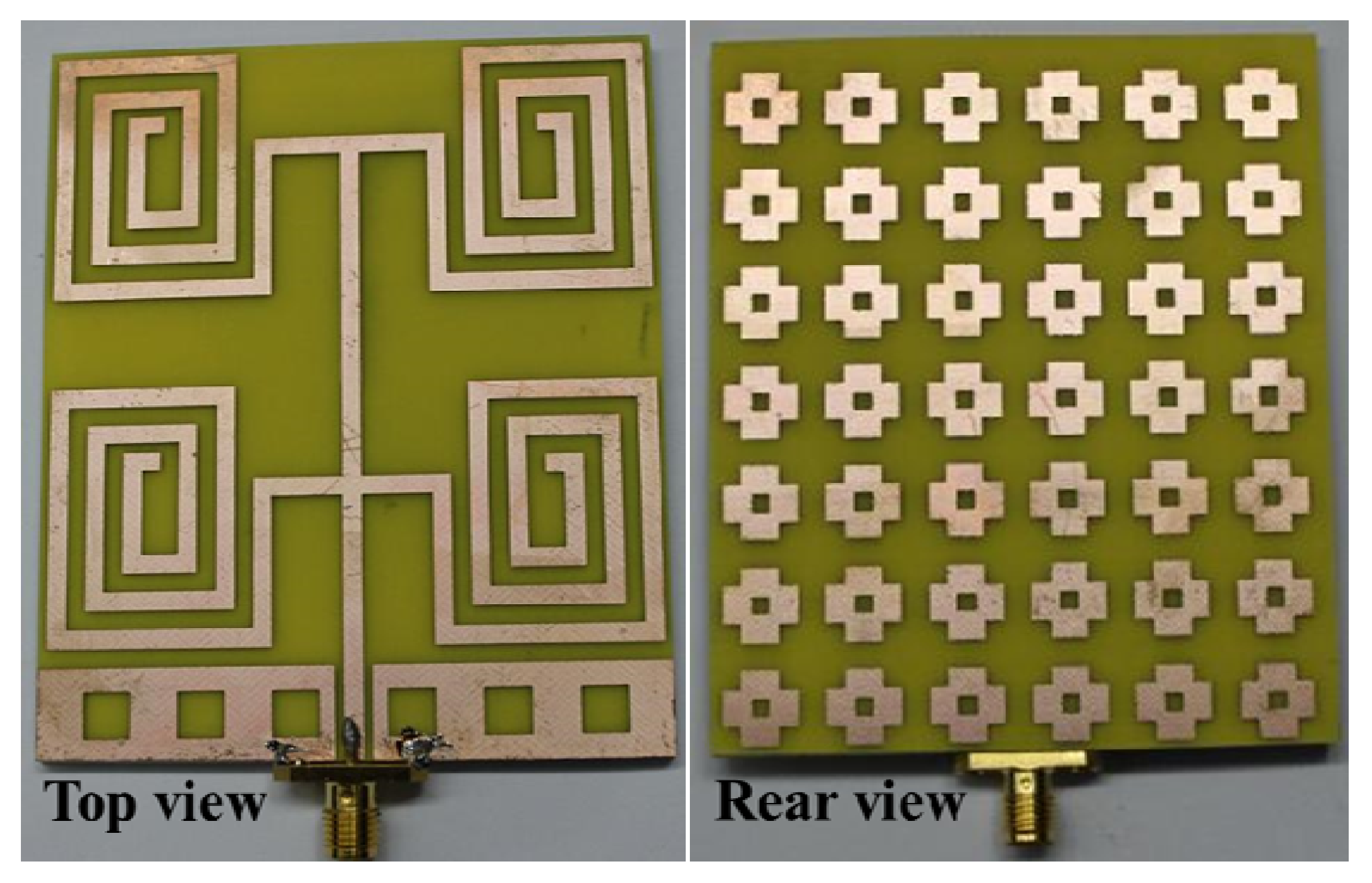
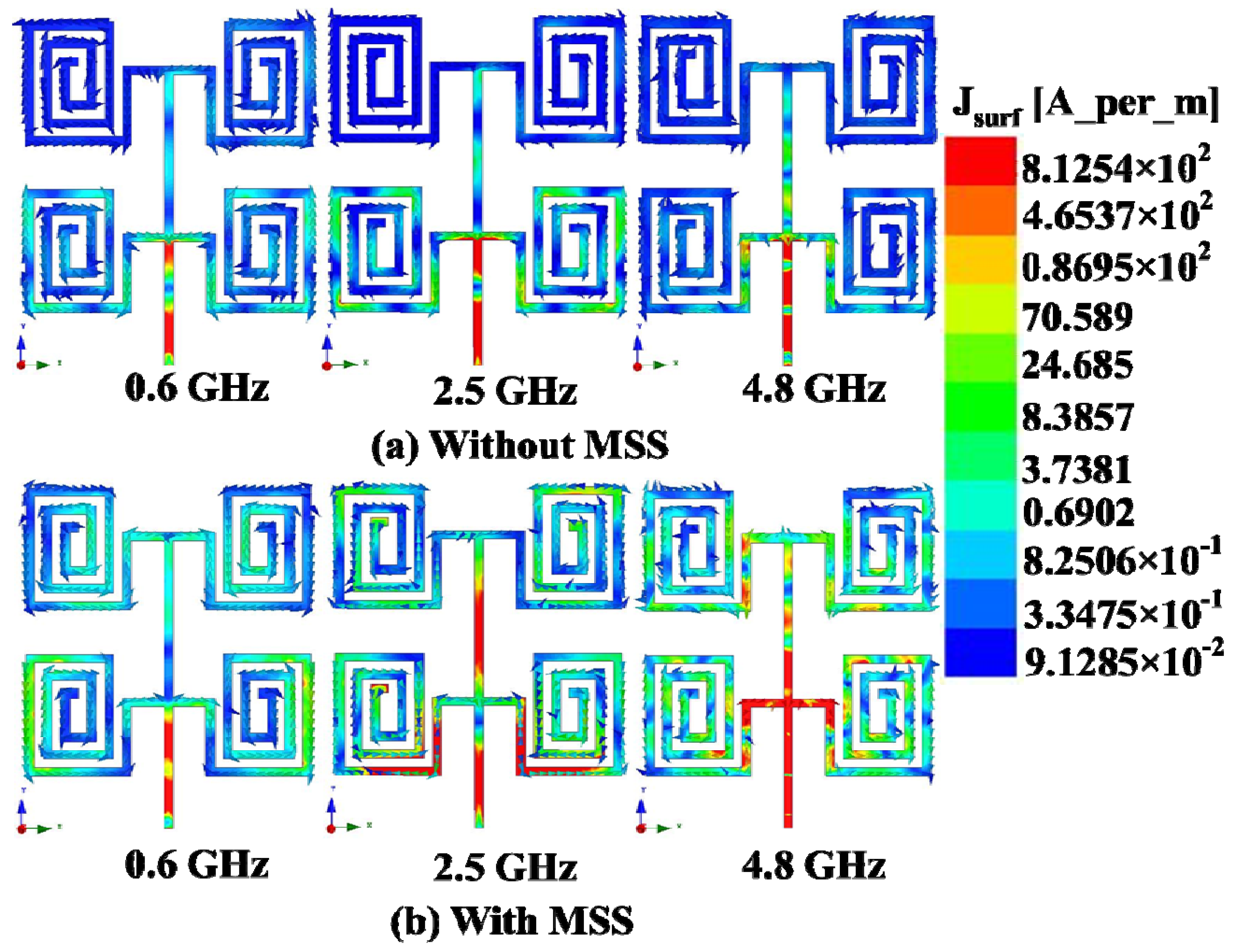
 . The effective permeability (μeff) and effective permittivity (εeff) are shown in Figure 3a,b. The effective epsilon and mu values were extracted with commonly used effective parameter retrieval methods [19,21]. The effective permeability (μeff) and effective permittivity (εeff) are obtained from the finite-element-method-based simulator HFSS version 13.0.2. It can be clearly observed that the effective permeability is between zero and one in the bands of interest, as expected. With the aid of Snell’s law [22], the refractive index n can be defined as that shown in Figure 3c. The refractive index of the proposed MSS is close to zero in the operating bands. Therefore, the effective index of refraction is negative in the 3.4 GHz to 3.6 GHz range. However, the value of the refractive index of the MSS is close to zero and positive within the bands of interest, which are 0.4–0.9 GHz, 2.3–2.75 GHz and 4.6–4.9 GHz. The radiated electromagnetic field of the MSS element produces an internal oscillation, which introduces an identical illumination that improves the overall radiation performance. One of the vital issues in the MSS is interaction with the antenna element. In addition, the MSS reduces the mutual coupling between the antenna array elements. The key approach used in the design is to excite resonant oscillations in the MSS inclusion, and thus the fractional limpidity of the structure can be maintained [23]. The flowing currents induced in the MSS elements at certain frequencies cancel each other, thus permitting the incident wave to circulate. After the successful design and analysis of the proposed NZRI MSS-backed square-loop array antenna, a prototype was fabricated using an LPKF indoor Printed Circuit Board (PCB) prototyping machine. The fabricated prototype of the proposed NZRI MSS-backed antenna is shown in Figure 4.


3. Measurement Results


| Parameter | With MSS | Without MSS | ||||
|---|---|---|---|---|---|---|
| 1st Band | 2nd Band | 3rd Band | 1st Band | 2nd Band | 3rd Band | |
| Bandwidth | 500 MHz | 450 MHz | 300 MHz | 400 MHz | 700 MHz | 400 MHz |
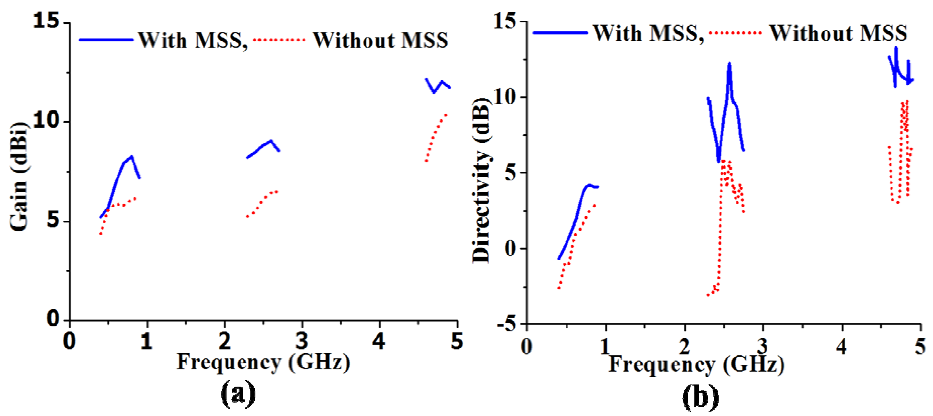
| Maximum Gain | 8.25 dBi | 9.05 dBi | 12.15 dBi | 6.21 dBi | 6.52 dBi | 10.54 dBi |
| Maximum Directivity | 4.17 dB | 12.22 dB | 13.23 dB | 2.99 dB | 5.93 dB | 9.81 dB |
4. Conclusions
Acknowledgments
Conflicts of Interest
References
- Veselago, V. The electrodynamics of substances with simultaneously negative values of ε and μ. Sov. Phys. Uspekhi 1968, 10, 509–514. [Google Scholar] [CrossRef]
- Islam, M.T.; Ullah, M.H.; Singh, M.J.; Faruque, M.R.I. A new metasurface superstrate structure for antenna performance enhancement. Materials 2013, 6, 3226–3240. [Google Scholar] [CrossRef]
- Chaimool, S.; Chung, K.L.; Akkaraekthalin, P. Bandwidth and gain enhancement of microstrip patch antennas using reflective metasurface. IEICE Trans. Commun. 2010, E93-B, 2496–2503. [Google Scholar] [CrossRef]
- Chung, K.L.; Chaimool, S. Broadside gain and bandwidth enhancement of microstrip patch antenna using a MNZ-metasurface. Microw. Opt. Technol. Lett. 2012, 54, 529–532. [Google Scholar] [CrossRef]
- Habib Ullah, M.; Islam, M.T.; Mandeep, J.S.; Misran, N.; Nikabdullah, N. A compact wideband antenna on dielectric material substrate for K band. Electron. Electr. Eng. 2012, 123. [Google Scholar]
- Honari, M.M.; Abdipour, A.; Moradi, G. Bandwidth and gain enhancement of an aperture antenna with modified ring patch. IEEE Antennas Wirel. Propag. Lett. 2011, 10, 1413–1416. [Google Scholar] [CrossRef]
- Yang, G.-M.; Xing, X.; Daigle, A.; Obi, O.; Liu, M.; Lou, J.; Stoute, S.; Naishadham, K.; Sun, N.X. Planar annular ring antennas with multilayer self-biased NiCo-Ferrite films loading. IEEE Trans. Antennas Propag. 2010, 58, 648–655. [Google Scholar] [CrossRef]
- Munk, B.A. Frequency Selective Surfaces: Theory and Design; John Wiley & Sons: Hoboken, NJ, USA, 2005. [Google Scholar]
- Lee, Y.J.; Yeo, J.; Mittra, R.; Park, W.S. Design of a high-directivity Electromagnetic Band Gap (EBG) resonator antenna using a frequency-selective surface (FSS) superstrate. Microw. Opt. Technol. Lett. 2004, 43, 462–467. [Google Scholar] [CrossRef]
- Yang, F.-R.; Ma, K.-P.; Qian, Y.; Itoh, T. A uniplanar compact photonic-bandgap (UC-PBG) structure and its applications for microwave circuit. IEEE Trans. Microw. Theory Tech. 1999, 47, 1509–1514. [Google Scholar] [CrossRef]
- Ge, Y.; Esselle, K.P.; Bird, T.S. The use of simple thin partially reflective surfaces with positive reflection phase gradients to design wideband, low-profile EBG resonator antennas. IEEE Trans. Antennas Propag. 2012, 60, 743–750. [Google Scholar] [CrossRef]
- Enoch, S.; Tayeb, G.; Sabouroux, P.; Guérin, N.; Vincent, P. A metamaterial for directive emission. Phys. Rev. Lett. 2002, 89. [Google Scholar] [CrossRef] [PubMed]
- Garg, R.; Bhartia, P.; Bahl, I.; Ittipiboon, A. Microstrip Antenna Design Handbook; Massachusetts, Artech House Inc.: London, UK, 2001. [Google Scholar]
- Zhou, H.; Pei, Z.; Qu, S.; Zhang, S.; Wang, J.; Li, Q.; Xu, Z. A planar zero-index metamaterial for directive emission. J. Electromagn. Waves Appl. 2009, 23, 953–962. [Google Scholar] [CrossRef]
- Valentine, J.; Zhang, S.; Zentgraf, T.; Ulin-Avila, E.; Genov, D.A.; Bartal, G.; Zhang, X. Three-dimensional optical metamaterial with a negative refractive index. Nature 2008, 455, 376–379. [Google Scholar] [CrossRef] [PubMed]
- Saenz, E.; Ederra, I.; Gonzalo, R.; Pivnenko, S.; Breinbjerg, O.; de Maagt, P. Coupling reduction between dipole antenna elements by using a planar meta-surface. Antennas Propag. IEEE Trans. 2009, 57, 383–394. [Google Scholar] [CrossRef]
- Balanis, C.A. Antenna Theory: Analysis and Design, 3rd ed.; Wiley-Interscience: New York, NY, USA, 2012. [Google Scholar]
- Smith, D.R.; Schultz, S.; Markos, P.; Soukoulis, C.M. Determination of effective permittivity and permeability of metamaterials from reflection and transmission coefficients. Phys. Rev. B 2002, 65. [Google Scholar] [CrossRef]
- Laure, P.; Puaux, G.; Silva, L.; Vincent, M. Permeability computation on a REV with an immersed finite element method. AIP Conf. Proc. 2011, 1353, 978–983. [Google Scholar]
- Chaimool, S.; Rakluea, C.; Akkaraekthalin, P. Mu-near-zero metasurface for microstrip-fed slot antennas. Appl. Phys. 2013, 112, 669–675. [Google Scholar] [CrossRef]
- Berdichevsky, A.L.; Cai, Z. Preform permeability predictions by self-consistent method and finite element simulation. Polym. Compos. 1993, 14, 132–143. [Google Scholar] [CrossRef]
- Shelby, R.A.; Smith, D.R.; Schultz, S. Experimental verification of a negative index of refraction. Science 2001, 292, 77–79. [Google Scholar] [CrossRef] [PubMed]
- Agarwal, K.; Nasimuddin; Alphones, A. RIS-based compact circularly polarized microstrip antennas. IEEE Trans. Antennas Propag. 2013, 61, 547–554. [Google Scholar] [CrossRef]
- Cook, B.S.; Shamim, A. Utilizing wideband AMC structures for high-gain inkjet-printed antennas on lossy paper substrate. IEEE Antennas Wirel. Propag. Lett. 2013, 12, 76–79. [Google Scholar] [CrossRef]
- Mandal, K.; Sarkar, P.P. A compact high gain microstrip antenna for wireless applications. AEU Int. J. Electron. Commun. 2013, 67, 1010–1014. [Google Scholar] [CrossRef]
© 2013 by the authors; licensee MDPI, Basel, Switzerland. This article is an open access article distributed under the terms and conditions of the Creative Commons Attribution license (http://creativecommons.org/licenses/by/3.0/).
Share and Cite
Ullah, M.H.; Islam, M.T.; Faruque, M.R.I. A Near-Zero Refractive Index Meta-Surface Structure for Antenna Performance Improvement. Materials 2013, 6, 5058-5068. https://doi.org/10.3390/ma6115058
Ullah MH, Islam MT, Faruque MRI. A Near-Zero Refractive Index Meta-Surface Structure for Antenna Performance Improvement. Materials. 2013; 6(11):5058-5068. https://doi.org/10.3390/ma6115058
Chicago/Turabian StyleUllah, Mohammad Habib, Mohammad Tariqul Islam, and Mohammad Rashed Iqbal Faruque. 2013. "A Near-Zero Refractive Index Meta-Surface Structure for Antenna Performance Improvement" Materials 6, no. 11: 5058-5068. https://doi.org/10.3390/ma6115058
APA StyleUllah, M. H., Islam, M. T., & Faruque, M. R. I. (2013). A Near-Zero Refractive Index Meta-Surface Structure for Antenna Performance Improvement. Materials, 6(11), 5058-5068. https://doi.org/10.3390/ma6115058