
Binder Jetting 3D Printing of Binary Cement—Siliceous Sand Mixture


Abstract
:1. Introduction
2. Materials and Methods
3. Results
3.1. Flowability
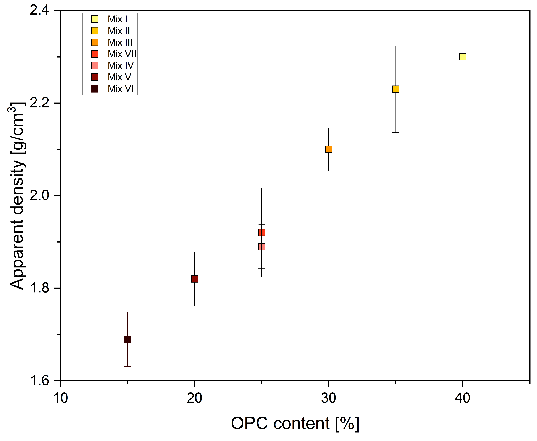
3.2. Density
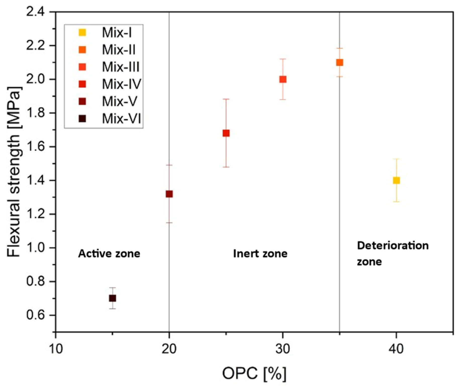
3.3. Mechanical Properties
3.4. Microscopic Analysis
4. Conclusions
- The flow characteristics of mixtures with lower OPC content were good to fair, while those with higher OPC content showed passable to cohesive/poor flow. The Hausner ratio (HR) and Carr’s index (CI) show that flow dynamics were affected by the steady increase in OPC concentration. These results indicate the significance of OPC concentration in determining the general flow behavior of binary cement mixtures and provide important information for uses in 3D printing technology.
- The OPC content plays a critical role in improving the overall density of the 3D-printed specimens. As the proportion of OPC cement exceeds that of quick-setting cement, the higher specific gravity of OPC becomes the primary factor in improving the overall density and the mechanical properties of the material.
- Mix-VII exhibits relatively high flexural strength, peaking at 1.9 MPa after seven days and increasing to 2.7 MPa by the 28th day. Further highlighting Mix-VII’s strong mechanical performance is this positive trend in compressive strength over time.
- Variable binary cement content improves mechanical properties up to 35:5:60 wt% of OPC:QSC:sand; above that, more cement content causes the strength to decrease.
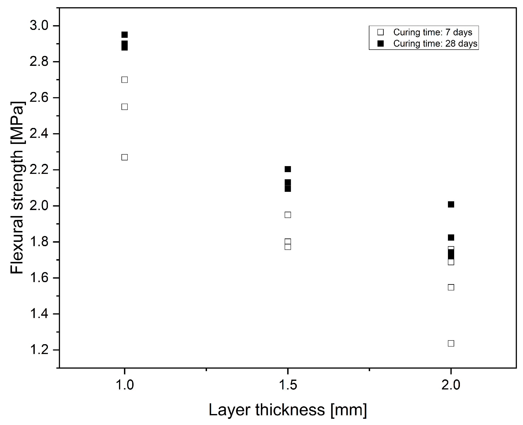
- The findings show that there is an apparent reduction in mechanical strength as layer thickness increases. This result implies that the mechanical strength and layer thickness are inversely related. This observed pattern emphasizes how crucial it is to take layer thickness into account as an essential.
- Microscopic analysis confirms a correlation between strength and voids at different layer thicknesses, with the increase in voids appearing as the source of the strength decrease. In conclusion, our research clearly shows how layer thickness affects void formation and mechanical strength in printed concrete samples.
Author Contributions
Funding
Institutional Review Board Statement
Informed Consent Statement
Data Availability Statement
Acknowledgments
Conflicts of Interest
References
- Labonnote, N.; Rønnquist, A.; Manum, B.; Rüther, P. Additive Construction: State-of-the-Art, Challenges and Opportunities. Autom. Constr. 2016, 72, 347–366. [Google Scholar] [CrossRef]
- Bos, F.; Wolfs, R.; Ahmed, Z.; Salet, T. Additive Manufacturing of Concrete in Construction: Potentials and Challenges of 3D Concrete Printing. Virtual Phys. Prototyp. 2016, 11, 209–225. [Google Scholar] [CrossRef]
- Tay, Y.W.D.; Panda, B.; Paul, S.C.; Noor Mohamed, N.A.; Tan, M.J.; Leong, K.F. 3D Printing Trends in Building and Construction Industry: A Review. Virtual Phys. Prototyp. 2017, 12, 261–276. [Google Scholar] [CrossRef]
- Miranda, P.; Pajares, A.; Saiz, E.; Tomsia, A.P.; Guiberteau, F. Mechanical Properties of Calcium Phosphate Scaffolds Fabricated by Robocasting. J. Biomed. Mater. Res. A 2008, 85, 218–227. [Google Scholar] [CrossRef] [PubMed]
- Khoshnevis, B. Automated Construction by Contour Crafting—Related Robotics and Information Technologies. Autom. Constr. 2004, 13, 5–19. [Google Scholar] [CrossRef]
- Casas-Luna, M.; Torres-Rodríguez, J.A.; Valdés-Martínez, O.U.; Obradović, N.; Slámečka, K.; Maca, K.; Kaiser, J.; Montúfar, E.B.; Čelko, L. Robocasting of Controlled Porous CaSiO3–SiO2 Structures: Architecture—Strength Relationship and Material Catalytic Behavior. Ceram. Int. 2020, 46, 8853–8861. [Google Scholar] [CrossRef]
- Böckin, D.; Tillman, A.M. Environmental Assessment of Additive Manufacturing in the Automotive Industry. J. Clean. Prod. 2019, 226, 977–987. [Google Scholar] [CrossRef]
- Haleem, A.; Javaid, M. 3D Printed Medical Parts with Different Materials Using Additive Manufacturing. Clin. Epidemiol. Glob. Health 2020, 8, 215–223. [Google Scholar] [CrossRef]
- ISO/ASTM 52900:2021; Additive Manufacturing—General Principles—Fundamentals and Vocabulary. ISO: Geneva, Switzerland, 2021. Available online: https://www.iso.org/standard/74514.html (accessed on 13 March 2024).
- Vaezi, M.; Chua, C.K. Effects of Layer Thickness and Binder Saturation Level Parameters on 3D Printing Process. Int. J. Adv. Manuf. Technol. 2011, 53, 275–284. [Google Scholar] [CrossRef]
- Lloret, E.; Shahab, A.R.; Linus, M.; Flatt, R.J.; Gramazio, F.; Kohler, M.; Langenberg, S. Complex Concrete Structures: Merging Existing Casting Techniques with Digital Fabrication. Comput.-Aided Des. 2015, 60, 40–49. [Google Scholar] [CrossRef]
- Johnston: Design and Construction of Concrete Formwork—Google Scholar. Available online: https://scholar.google.com/scholar_lookup?title=Design%20and%20construction%20of%20concrete%20formwork&publication_year=2008&author=D.W.%20Johnston (accessed on 4 December 2023).
- Daguano, J.K.M.B.; Santos, C.; Alves, M.F.R.P.; da Silva, J.V.L.; Souza, M.T.; Fernandes, M.H.F.V. State of the Art in the Use of Bioceramics to Elaborate 3D Structures Using Robocasting. Int. J. Adv. Med. Biotechnol. 2019, 2, 55–70. [Google Scholar] [CrossRef]
- Zocca, A.; Colombo, P.; Gomes, C.M.; Günster, J. Additive Manufacturing of Ceramics: Issues, Potentialities, and Opportunities. J. Am. Ceram. Soc. 2015, 98, 1983–2001. [Google Scholar] [CrossRef]
- Sachs, E.; Cima, M.; Williams, P.; Brancazio, D.; Cornie, J. Three Dimensional Printing: Rapid Tooling and Prototypes Directly from a CAD Model. J. Manuf. Sci. Eng. Trans. ASME 1992, 114, 481–488. [Google Scholar] [CrossRef]
- Ziaee, M.; Crane, N. Binder Jetting: A Review of Process, Materials, and Methods. Addit. Manuf. 2019, 28, 781–801. [Google Scholar] [CrossRef]
- Gibson, I.; Rosen, D.; Stucker, B. Binder Jetting. In Additive Manufacturing Technologies; Springer: New York, NY, USA, 2015; pp. 205–218. [Google Scholar] [CrossRef]
- Seitz, H.; Rieder, W.; Irsen, S.; Leukers, B.; Tille, C. Three-Dimensional Printing of Porous Ceramic Scaffolds for Bone Tissue Engineering. J. Biomed. Mater. Res. B Appl. Biomater. 2005, 74B, 782–788. [Google Scholar] [CrossRef] [PubMed]
- Zocca, A.; Günster, J.; Zocca, A.; Lima, P.; Günster, J. LSD-Based 3D Printing of Alumina Ceramics. J. Ceram. Sci. Technol. 2017, 8, 141–148. [Google Scholar] [CrossRef]
- Xia, M.; Nematollahi, B.; Sanjayan, J. Influence of Binder Saturation Level on Compressive Strength and Dimensional Accuracy of Powder-Based 3D Printed Geopolymer. Mater. Sci. Forum 2018, 939, 177–183. [Google Scholar] [CrossRef]
- Lv, X.; Ye, F.; Cheng, L.; Fan, S.; Liu, Y. Binder Jetting of Ceramics: Powders, Binders, Printing Parameters, Equipment, and Post-Treatment. Ceram. Int. 2019, 45, 12609–12624. [Google Scholar] [CrossRef]
- Miyanaji, H.; Momenzadeh, N.; Yang, L. Effect of Printing Speed on Quality of Printed Parts in Binder Jetting Process. Addit. Manuf. 2018, 20, 1–10. [Google Scholar] [CrossRef]
- Wu, C.; Fan, W.; Zhou, Y.; Luo, Y.; Gelinsky, M.; Chang, J.; Xiao, Y. 3D-Printing of Highly Uniform CaSiO3 Ceramic Scaffolds: Preparation, Characterization and In Vivo Osteogenesis. J. Mater. Chem. 2012, 22, 12288–12295. [Google Scholar] [CrossRef]
- Bergmann, C.; Lindner, M.; Zhang, W.; Koczur, K.; Kirsten, A.; Telle, R.; Fischer, H. 3D Printing of Bone Substitute Implants Using Calcium Phosphate and Bioactive Glasses. J. Eur. Ceram. Soc. 2010, 30, 2563–2567. [Google Scholar] [CrossRef]
- Jones, J.R.; Hench, L.L. Regeneration of Trabecular Bone Using Porous Ceramics. Curr. Opin. Solid State Mater. Sci. 2003, 7, 301–307. [Google Scholar] [CrossRef]
- Utela, B.; Storti, D.; Anderson, R.; Ganter, M. A Review of Process Development Steps for New Material Systems in Three Dimensional Printing (3DP). J. Manuf. Process 2008, 10, 96–104. [Google Scholar] [CrossRef]
- Zhou, Z.; Lennon, A.; Buchanan, F.; McCarthy, H.O.; Dunne, N. Binder Jetting Additive Manufacturing of Hydroxyapatite Powders: Effects of Adhesives on Geometrical Accuracy and Green Compressive Strength. Addit. Manuf. 2020, 36, 101645. [Google Scholar] [CrossRef]
- Withell, A.; Diegel, O.; Grupp, I.; Reay, S.; De Beer, D.; Potgieter, J. Porous Ceramic Filters through 3D Printing. In Innovative Developments in Virtual and Physical Prototyping, Proceedings of the 5th International Conference on Advanced Research and Rapid Prototyping, Leiria, Portugal, 28 September–1 October 2011; Taylor & Francis: London, UK, 2012; pp. 313–318. [Google Scholar] [CrossRef]
- Butscher, A.; Bohner, M.; Doebelin, N.; Hofmann, S.; Müller, R. New Depowdering-Friendly Designs for Three-Dimensional Printing of Calcium Phosphate Bone Substitutes. Acta Biomater. 2013, 9, 9149–9158. [Google Scholar] [CrossRef] [PubMed]
- Chumnanklang, R.; Panyathanmaporn, T.; Sitthiseripratip, K.; Suwanprateeb, J. 3D Printing of Hydroxyapatite: Effect of Binder Concentration in Pre-Coated Particle on Part Strength. Mater. Sci. Eng. C 2007, 27, 914–921. [Google Scholar] [CrossRef]
- Butscher, A.; Bohner, M.; Doebelin, N.; Galea, L.; Loeffel, O.; Müller, R. Moisture Based Three-Dimensional Printing of Calcium Phosphate Structures for Scaffold Engineering. Acta Biomater. 2013, 9, 5369–5378. [Google Scholar] [CrossRef]
- Zhou, Z.; Mitchell, C.A.; Buchanan, F.J.; Dunne, N.J. Effects of Heat Treatment on the Mechanical and Degradation Properties of 3D-Printed Calcium-Sulphate-Based Scaffolds. Corp. ISRN Biomater. 2013, 2013, 750720. [Google Scholar] [CrossRef]
- Geldart, D.; Abdullah, E.C.; Hassanpour, A.; Nwoke, L.C.; Wouters, I. Characterization of Powder Flowability Using Measurement of Angle of Repose. China Particuology 2006, 4, 3–4. [Google Scholar] [CrossRef]
- Shakor, P.; Nejadi, S.; Paul, G.; Sanjayan, J. Dimensional Accuracy, Flowability, Wettability, and Porosity in Inkjet 3DP for Gypsum and Cement Mortar Materials. Autom. Constr. 2020, 110, 102964. [Google Scholar] [CrossRef]
- Moghadasi, M.; Du, W.; Li, M.; Pei, Z.; Ma, C. Ceramic Binder Jetting Additive Manufacturing: Effects of Particle Size on Feedstock Powder and Final Part Properties. Ceram. Int. 2020, 46, 16966–16972. [Google Scholar] [CrossRef]
- Chen, Y.; Jansen, K.; Zhang, H.; Romero Rodriguez, C.; Gan, Y.; Çopuroğlu, O.; Schlangen, E. Effect of Printing Parameters on Interlayer Bond Strength of 3D Printed Limestone-Calcined Clay-Based Cementitious Materials: An Experimental and Numerical Study. Constr. Build. Mater. 2020, 262, 120094. [Google Scholar] [CrossRef]
- Du, W. Imece2017-70344 Binder Jetting Additive Manufacturing of Ceramics: A Literature. In Proceedings of the ASME 2017 International Mechanical Engineering Congress and Exposition, Safety Engineering and Risk Analysis, Tampa, FL, USA, 3–9 November 2017; pp. 1–12. [Google Scholar]
- Yao, A.W.L.; Tseng, Y.C. A Robust Process Optimization for a Powder Type Rapid Prototyper. Rapid Prototyp. J. 2002, 8, 180–189. [Google Scholar] [CrossRef]
- Gonzalez, J.A.; Mireles, J.; Lin, Y.; Wicker, R.B. Characterization of Ceramic Components Fabricated Using Binder Jetting Additive Manufacturing Technology. Ceram. Int. 2016, 42, 10559–10564. [Google Scholar] [CrossRef]
- Farzadi, A.; Solati-Hashjin, M.; Asadi-Eydivand, M.; Osman, N.A.A. Effect of Layer Thickness and Printing Orientation on Mechanical Properties and Dimensional Accuracy of 3D Printed Porous Samples for Bone Tissue Engineering. PLoS ONE 2014, 9, e108252. [Google Scholar] [CrossRef] [PubMed]
- Dini, F.; Ghaffari, S.A.; Jafar, J.; Hamidreza, R.; Marjan, S. A Review of Binder Jet Process Parameters; Powder, Binder, Printing and Sintering Condition. Met. Powder Rep. 2020, 75, 95–100. [Google Scholar] [CrossRef]
- Mostafaei, A.; Elliott, A.M.; Barnes, J.E.; Li, F.; Tan, W.; Cramer, C.L.; Nandwana, P.; Chmielus, M. Binder Jet 3D Printing—Process Parameters, Materials, Properties, Modeling, and Challenges. Prog. Mater. Sci. 2021, 119, 100707. [Google Scholar] [CrossRef]
- Yu, S.; Xia, M.; Sanjayan, J.; Yang, L.; Xiao, J.; Du, H. Microstructural Characterization of 3D Printed Concrete. J. Build. Eng. 2021, 44, 102948. [Google Scholar] [CrossRef]
- Kloft, H.; Krauss, H.W.; Hack, N.; Herrmann, E.; Neudecker, S.; Varady, P.A.; Lowke, D. Influence of Process Parameters on the Interlayer Bond Strength of Concrete Elements Additive Manufactured by Shotcrete 3D Printing (SC3DP). Cem. Concr. Res. 2020, 134, 106078. [Google Scholar] [CrossRef]
- Huang, X.; Yang, W.; Song, F.; Zou, J. Study on the Mechanical Properties of 3D Printing Concrete Layers and the Mechanism of Influence of Printing Parameters. Constr. Build. Mater. 2022, 335, 127496. [Google Scholar] [CrossRef]
- Nair, S.A.O.; Tripati, A.; Neithalath, N. Examining Layer Height Effects on the Flexural and Fracture Response of Plain and Fiber-Reinforced 3D-Printed Beams. Cem. Concr. Compos. 2021, 124, 104254. [Google Scholar] [CrossRef]
- Ur Rehman, A.; Sglavo, V.M. 3D Printing of Portland Cement-Containing Bodies. Rapid Prototyp. J. 2022, 28, 197–203. [Google Scholar] [CrossRef]
- Ur Rehman, A.; Sglavo, V.M. 3D Printing of Geopolymer-Based Concrete for Building Applications. Rapid Prototyp. J. 2020, 26, 1783–1788. [Google Scholar] [CrossRef]
- Soltan, D.G.; Li, V.C. A Self-Reinforced Cementitious Composite for Building-Scale 3D Printing. Cem. Concr. Compos. 2018, 90, 1–13. [Google Scholar] [CrossRef]
- Shakor, P.; Nejadi, S.; Paul, G.; Sanjayan, J.; Nazari, A. Mechanical Properties of Cement-Based Materials and Effect of Elevated Temperature on 3-D Printed Mortar Specimens in Inkjet 3-D Printing. ACI Mater. J. 2019, 116, 55–67. [Google Scholar] [CrossRef]
- Shakor, P.; Nejadi, S.; Paul, G.; Sanjayan, J.; Aslani, F. Heat Curing as a Means of Postprocessing Influence on 3D Printed Mortar Specimens in Powderbased 3D Printing. Indian Concr. J. 2019, 93, 65–74. [Google Scholar]
- Bredt, J.; Anderson, T.; Russell, D.B. Three Dimensional Printing Material System and Method. U.S. Patent 7,332,537, 19 February 2008. [Google Scholar]
- Gibbons, G.; Williams, R.; Purnell, P.; Farahi, E. 3D Printing of Cement Composites. Adv. Appl. Ceram. 2010, 109, 287–290. [Google Scholar] [CrossRef]
- Zhou, Z.; Buchanan, F.; Mitchell, C.; Dunne, N. Printability of Calcium Phosphate: Calcium Sulfate Powders for the Application of Tissue Engineered Bone Scaffolds Using the 3D Printing Technique. Mater. Sci. Eng. C Mater. Biol. Appl. 2014, 38, 1–10. [Google Scholar] [CrossRef]
- Klammert, U.; Vorndran, E.; Reuther, T.; Müller, F.A.; Zorn, K.; Gbureck, U. Low Temperature Fabrication of Magnesium Phosphate Cement Scaffolds by 3D Powder Printing. J. Mater. Sci. Mater. Med. 2010, 21, 2947–2953. [Google Scholar] [CrossRef]
- Shakor, P.; Sanjayan, J.; Nazari, A.; Nejadi, S. Modified 3D Printed Powder to Cement-Based Material and Mechanical Properties of Cement Scaffold Used in 3D Printing. Constr. Build. Mater. 2017, 138, 398–409. [Google Scholar] [CrossRef]
- Lowke, D.; Talke, D.; Dressler, I.; Weger, D.; Gehlen, C.; Ostertag, C.; Rael, R. Particle Bed 3D Printing by Selective Cement Activation—Applications, Material and Process Technology. Cem. Concr. Res. 2020, 134, 106077. [Google Scholar] [CrossRef]
- C642; Standard Test Method for Density, Absorption, and Voids in Hardened Concrete. ASTM: West Conshohocken, PA, USA, 2022. Available online: https://www.astm.org/standards/c642 (accessed on 31 January 2024).
- UNI EN 196-1:2016; UNI Ente Italiano di Normazione. European Committee for Standardization: Brussels, Belgium, 2016. Available online: https://store.uni.com/uni-en-196-1-2016 (accessed on 6 September 2023).
- C1723; Standard Guide for Examination of Hardened Concrete Using Scanning Electron Microscopy. ASTM: West Conshohocken, PA, USA, 2022. Available online: https://www.astm.org/c1723-16r22.html (accessed on 4 December 2023).
- Qiu, M.; Sun, Y.; Qian, Y. Interfacial Bonding Performance of 3D-Printed Ultra-High Performance Strain-Hardening Cementitious Composites (UHP-SHCC) and Cast Normal Concrete. J. Build. Eng. 2024, 82, 108268. [Google Scholar] [CrossRef]
- Horpibulsuk, S.; Horpibulsuk, S. Strength and Microstructure of Cement Stabilized Clay. In Scanning Electron Microscopy; IntechOpen: London, UK, 2012. [Google Scholar] [CrossRef]


| Mixture | Content (Sand:OPC:QSC) wt% |
|---|---|
| Mix-I | 50:40:10 |
| Mix-II | 60:35:5 |
| Mix-III | 70:30:0 |
| Mix-IV | 70:25:5 |
| Mix-V | 70:20:10 |
| Mix-VI | 70:15:15 |
| Mix-VII | 75:25:0 |
| Mixture | HR | CI | Flow Character |
|---|---|---|---|
| Mix-I | 1.35 | 26 | Cohesive/poor |
| Mix-II | 1.31 | 24 | Passable |
| Mix-III | 1.28 | 22 | Passable |
| Mix-IV | 1.28 | 22 | Passable |
| Mix-V | 1.21 | 18 | Fair |
| Mix-VI | 1.17 | 15 | Good |
| Mix-VII | 1.23 | 19 | Fair |
Disclaimer/Publisher’s Note: The statements, opinions and data contained in all publications are solely those of the individual author(s) and contributor(s) and not of MDPI and/or the editor(s). MDPI and/or the editor(s) disclaim responsibility for any injury to people or property resulting from any ideas, methods, instructions or products referred to in the content. |
© 2024 by the authors. Licensee MDPI, Basel, Switzerland. This article is an open access article distributed under the terms and conditions of the Creative Commons Attribution (CC BY) license (https://creativecommons.org/licenses/by/4.0/).
Share and Cite
Shahid, M.; Sglavo, V.M. Binder Jetting 3D Printing of Binary Cement—Siliceous Sand Mixture. Materials 2024, 17, 1514. https://doi.org/10.3390/ma17071514
Shahid M, Sglavo VM. Binder Jetting 3D Printing of Binary Cement—Siliceous Sand Mixture. Materials. 2024; 17(7):1514. https://doi.org/10.3390/ma17071514
Chicago/Turabian StyleShahid, Mursaleen, and Vincenzo M. Sglavo. 2024. "Binder Jetting 3D Printing of Binary Cement—Siliceous Sand Mixture" Materials 17, no. 7: 1514. https://doi.org/10.3390/ma17071514
APA StyleShahid, M., & Sglavo, V. M. (2024). Binder Jetting 3D Printing of Binary Cement—Siliceous Sand Mixture. Materials, 17(7), 1514. https://doi.org/10.3390/ma17071514