
Hybrid Ti6Al4V/Silk Fibroin Composite for Load-Bearing Implants: A Hierarchical Multifunctional Cellular Scaffold
 , , ,
, , ,
Abstract
:1. Introduction
2. Materials and Methods
2.1. Hybrid Scaffold Preparation
2.1.1. Ti6Al4V Cage Design and Manufacturing
2.1.2. Silk Fibroin and Silk Fibroin–Gelatin Solution Preparation
2.1.3. Preparation of the Hybrid Composite Scaffold
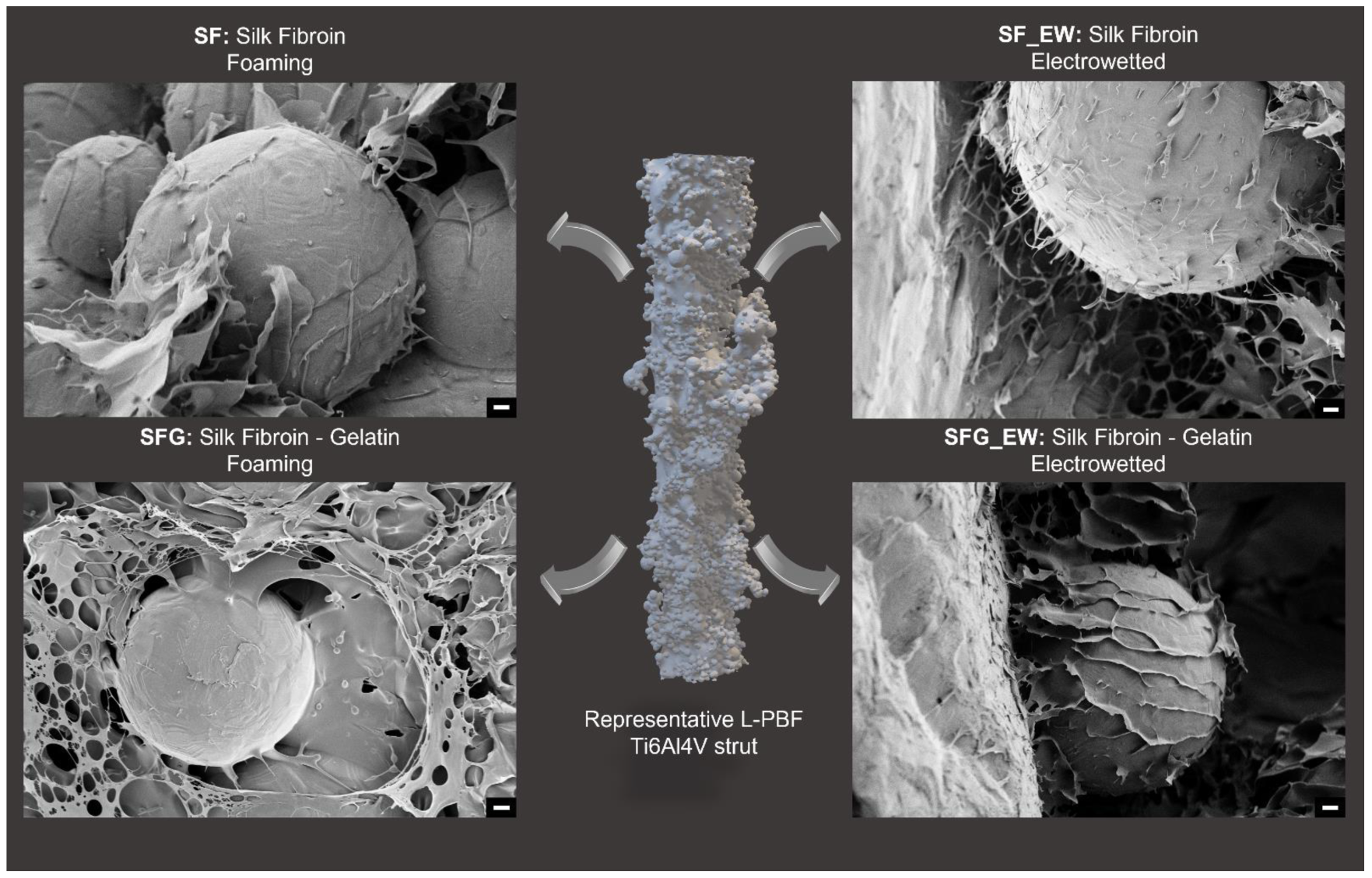
- SF: L-PBF titanium cage + 5% silk fibroin foam.
- SF_EW: L-PBF titanium cage + 5% silk fibroin electrowet foam.
- SFG: L-PBF titanium cage + 5% silk fibroin-gelatin foam.
- SFG_EW: L-PBF titanium cage + electrowet foam with 5% silk fibroin–gelatin.
Gas Foaming
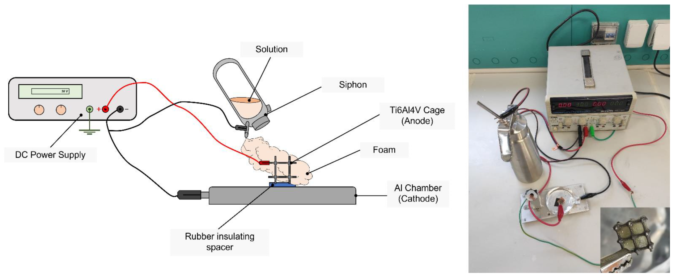
Electrowetting
2.2. Hybrid Composite Scaffold Characterization
2.2.1. Rheological Tests
- G: pure aqueous gelatin solution at 20% w/v concentration.
- G/SF 1:2: blend solution of gelatin and silk fibroin in a ratio G:SF of 1:2.
- G/SF 1:3: blend solution of gelatin and silk fibroin in a ratio G:SF of 1:3.
- G/SF 1:4: blend solution of gelatin and silk fibroin in a ratio G:SF of 1:4.
2.2.2. ξ-Potential
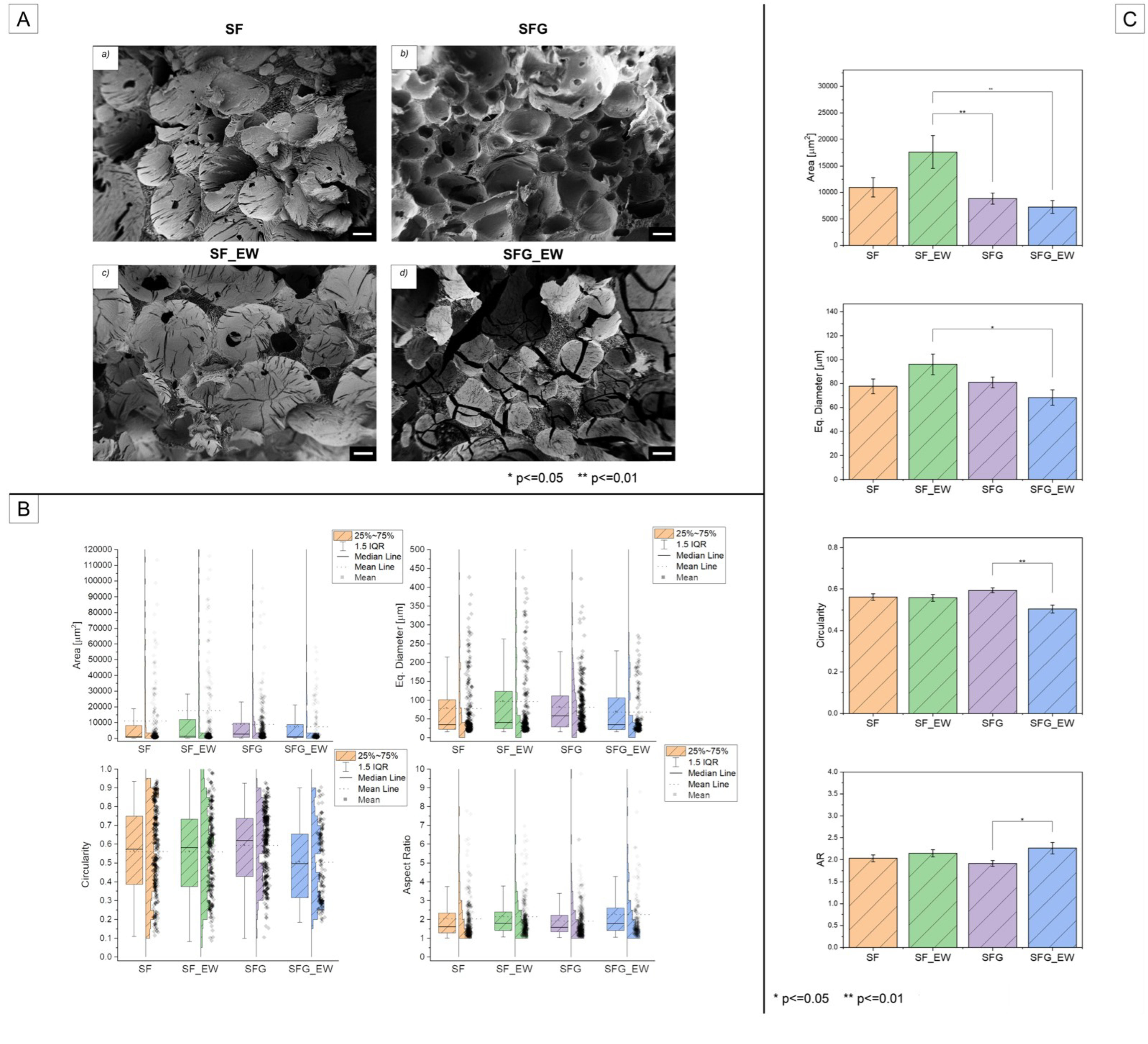
2.2.3. Scanning Electron Microscopy (SEM)
2.2.4. Porosity Analysis
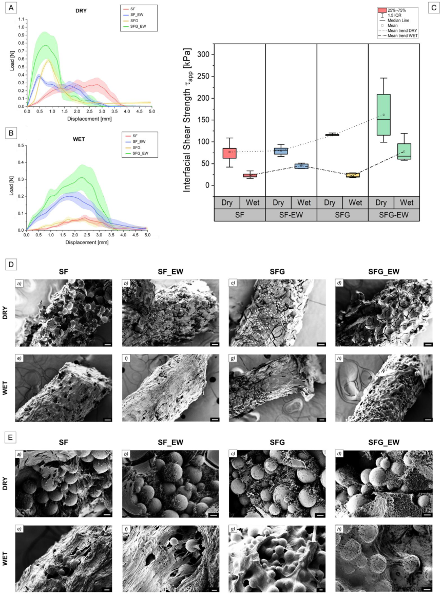
2.2.5. Pull-Out Tests
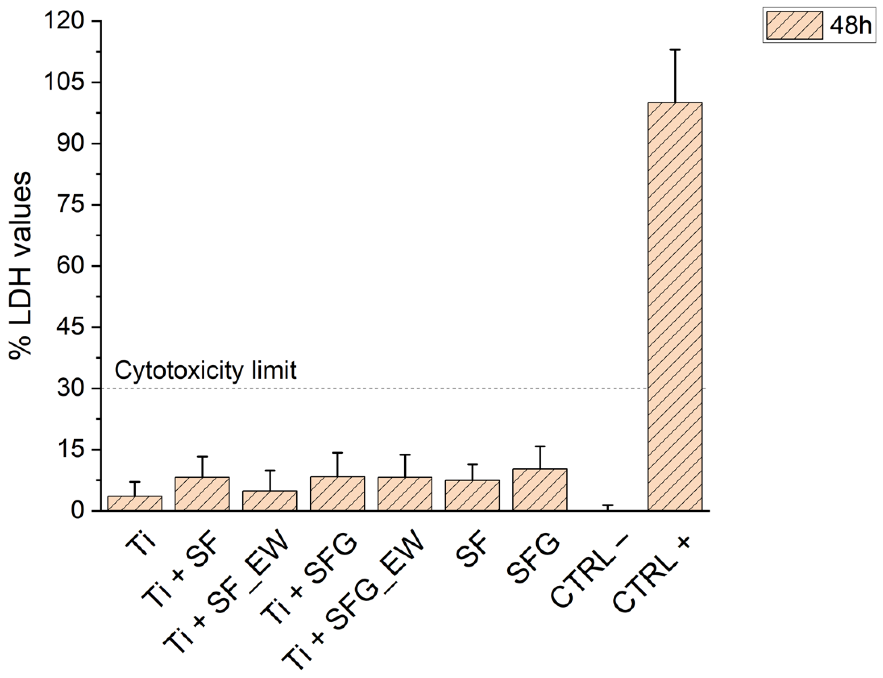
2.2.6. Cytotoxicity Assay
3. Results
3.1. Preliminary Solution Characterization
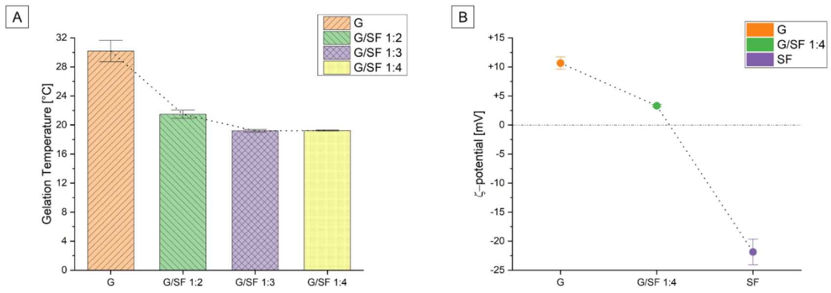
3.1.1. Rheological Tests
3.1.2. ξ-Potential
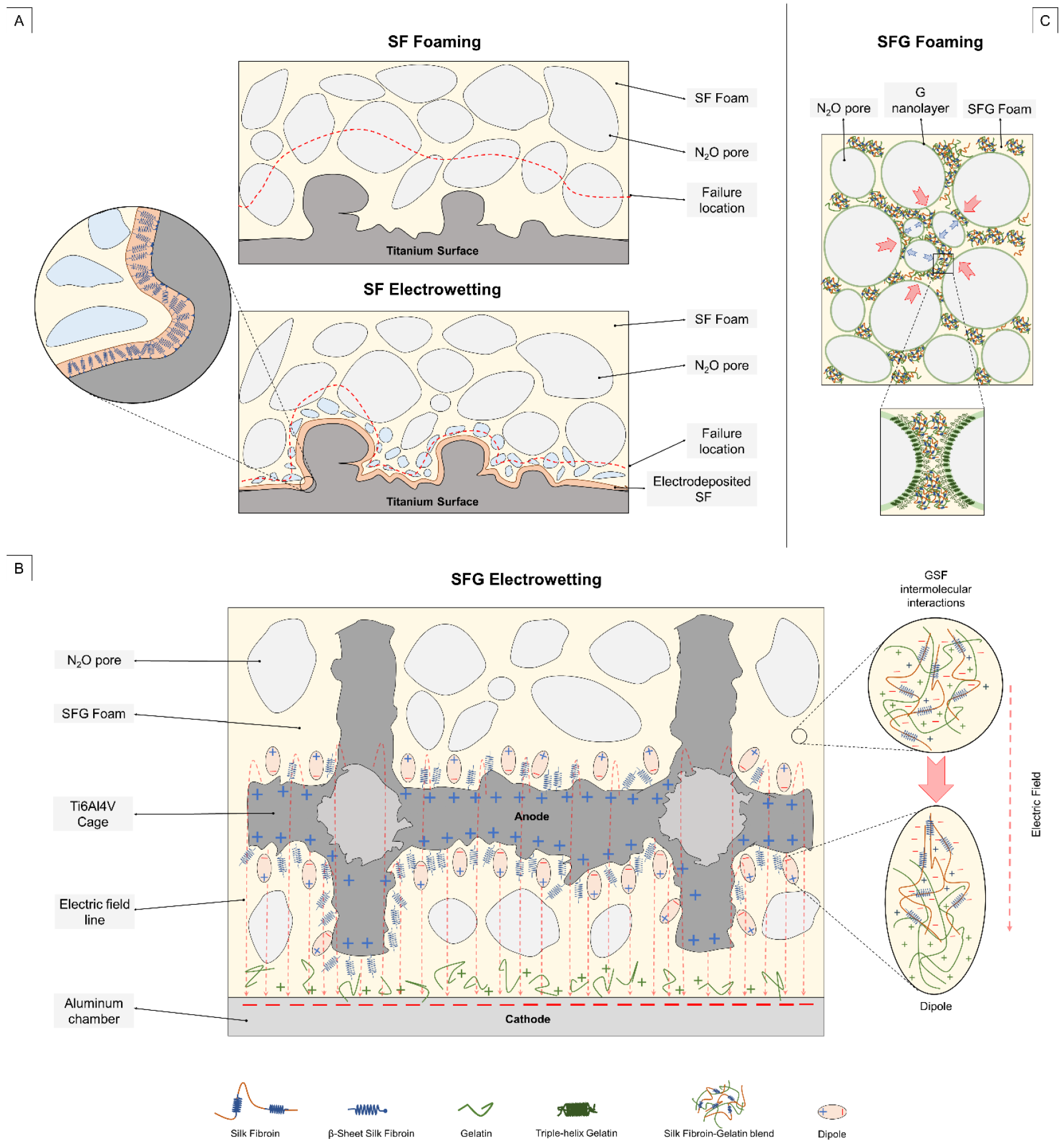
3.2. Polymer–Metal Interface Evaluation
3.3. Porosity Assessment
3.4. Pull-Out Test
3.5. Cytotoxicity Assessment
4. Conclusions
Supplementary Materials
Author Contributions
Funding
Institutional Review Board Statement
Informed Consent Statement
Data Availability Statement
Conflicts of Interest
References
- du Plessis, A.; Razavi, S.M.J.; Benedetti, M.; Murchio, S.; Leary, M.; Watson, M.; Bhate, D.; Berto, F. Properties and applications of additively manufactured metallic cellular materials: A review. Prog. Mater. Sci. 2022, 125, 100918. [Google Scholar] [CrossRef]
- Blakey-Milner, B.; Gradl, P.; Snedden, G.; Brooks, M.; Pitot, J.; Lopez, E.; Leary, M.; Berto, F.; du Plessis, A. Metal additive manufacturing in aerospace: A review. Mater. Des. 2021, 209, 110008. [Google Scholar] [CrossRef]
- Vafadar, A.; Guzzomi, F.; Rassau, A.; Hayward, K. Advances in metal additive manufacturing: A review of common processes, industrial applications, and current challenges. Appl. Sci. 2021, 11, 1213. [Google Scholar] [CrossRef]
- Harrysson, O.L.A.; Marcellin-Little, D.J.; Horn, T. Applications of Metal Additive Manufacturing in Veterinary Orthopedic Surgery. JOM 2015, 67, 647–654. [Google Scholar] [CrossRef]
- Murr, L.E.; Gaytan, S.M.; Medina, F.; Lopez, H.; Martinez, E.; Machado, B.I.; Hernandez, D.H.; Lopez, M.I.; Wicker, R.B.; Bracke, J. Next-generation biomedical implants using additive manufacturing of complex cellular and functional mesh arrays. Philos. Trans. R. Soc. Lond. Ser. A Math. Phys. Eng. Sci. 2010, 368, 1999–2032. [Google Scholar] [CrossRef]
- Zadpoor, A.A.; Malda, J. Additive Manufacturing of Biomaterials, Tissues, and Organs. Ann. Biomed. Eng. 2017, 45, 1–11. [Google Scholar] [CrossRef]
- Kumar, R.; Kumar, M.; Chohan, J.S. The role of additive manufacturing for biomedical applications: A critical review. J. Manuf. Process. 2021, 64, 828–850. [Google Scholar] [CrossRef]
- Tofail, S.A.; Koumoulos, E.P.; Bandyopadhyay, A.; Bose, S.; O’Donoghue, L.; Charitidis, C. Additive manufacturing: Scientific and technological challenges, market uptake and opportunities. Mater. Today 2018, 21, 22–37. [Google Scholar] [CrossRef]
- Pereira, T.; Kennedy, J.V.; Potgieter, J. A comparison of traditional manufacturing vs additive manufacturing, the best method for the job. Procedia Manuf. 2019, 30, 11–18. [Google Scholar] [CrossRef]
- Barba, D.; Alabort, E.; Reed, R. Synthetic bone: Design by additive manufacturing. Acta Biomater. 2019, 97, 637–656. [Google Scholar] [CrossRef]
- Wang, P.; Li, X.; Luo, S.; Nai, M.L.S.; Ding, J.; Wei, J. Additively manufactured heterogeneously porous metallic bone with biostructural functions and bone-like mechanical properties. J. Mater. Sci. Technol. 2021, 62, 173–179. [Google Scholar] [CrossRef]
- Tilton, M.; Borjali, A.; Isaacson, A.; Varadarajan, K.M.; Manogharan, G.P. On structure and mechanics of biomimetic meta-biomaterials fabricated via metal additive manufacturing. Mater. Des. 2021, 201, 109498. [Google Scholar] [CrossRef]
- Wang, Y.; Arabnejad, S.; Tanzer, M.; Pasini, D. Hip implant design with three-dimensional porous architecture of optimized graded density. J. Mech. Des. 2018, 140, 111406. [Google Scholar] [CrossRef]
- Moussa, A.; Rahman, S.; Xu, M.; Tanzer, M.; Pasini, D. Topology optimization of 3D-printed structurally porous cage for acetabular reinforcement in total hip arthroplasty. J. Mech. Behav. Biomed. Mater. 2020, 105, 103705. [Google Scholar] [CrossRef]
- Arabnejad, S.; Johnston, R.B.; Pura, J.A.; Singh, B.; Tanzer, M.; Pasini, D. High-strength porous biomaterials for bone replacement: A strategy to assess the interplay between cell morphology, mechanical properties, bone ingrowth and manufacturing constraints. Acta Biomater. 2016, 30, 345–356. [Google Scholar] [CrossRef]
- Dallago, M.; Raghavendra, S.; Luchin, V.; Zappini, G.; Pasini, D.; Benedetti, M. The role of node fillet, unit-cell size and strut orientation on the fatigue strength of Ti-6Al-4V lattice materials additively manufactured via laser powder bed fusion. Int. J. Fatigue 2021, 142, 105946. [Google Scholar] [CrossRef]
- Benedetti, M.; du Plessis, A.; Ritchie, R.; Dallago, M.; Razavi, S.; Berto, F. Architected cellular materials: A review on their mechanical properties towards fatigue-tolerant design and fabrication. Mater. Sci. Eng. R Rep. 2021, 144, 100606. [Google Scholar] [CrossRef]
- Yadroitsava, I.; du Plessis, A.; Yadroitsev, I. Bone regeneration on implants of titanium alloys produced by laser powder bed fusion: A review. Titan. Consum. Appl. 2019, 197–233. [Google Scholar] [CrossRef]
- Liverani, E.; Rogati, G.; Pagani, S.; Brogini, S.; Fortunato, A.; Caravaggi, P. Mechanical interaction between additive-manufactured metal lattice structures and bone in compression: Implications for stress shielding of orthopaedic implants. J. Mech. Behav. Biomed. Mater. 2021, 121, 104608. [Google Scholar] [CrossRef]
- Arabnejad, S.; Johnston, B.; Tanzer, M.; Pasini, D. Fully porous 3D printed titanium femoral stem to reduce stress-shielding following total hip arthroplasty. J. Orthop. Res. 2017, 35, 1774–1783. [Google Scholar] [CrossRef] [Green Version]
- Zhang, L.; Song, B.; Choi, S.-K.; Shi, Y. A topology strategy to reduce stress shielding of additively manufactured porous metallic biomaterials. Int. J. Mech. Sci. 2021, 197, 106331. [Google Scholar] [CrossRef]
- Baltatu, I.; Sandu, A.V.; Vlad, M.D.; Spataru, M.C.; Vizureanu, P.; Baltatu, M.S. Mechanical Characterization and In Vitro Assay of Biocompatible Titanium Alloys. Micromachines 2022, 13, 430. [Google Scholar] [CrossRef] [PubMed]
- Spataru, M.C.; Butnaru, M.; Sandu, A.V.; Vulpe, V.; Vlad, M.D.; Baltatu, M.S.; Geanta, V.; Voiculescu, I.; Vizureanu, P.; Solcan, C. In-depth assessment of new Ti-based biocompatible materials. Mater. Chem. Phys. 2021, 258, 123959. [Google Scholar] [CrossRef]
- Baltatu, M.S.; Vizureanu, P.; Sandu, A.V.; Florido-Suarez, N.; Saceleanu, M.V.; Mirza-Rosca, J.C. New titanium alloys, promising materials for medical devices. Materials 2021, 14, 5934. [Google Scholar] [CrossRef] [PubMed]
- Jam, A.; du Plessis, A.; Lora, C.; Raghavendra, S.; Pellizzari, M.; Benedetti, M. Manufacturability of lattice structures fabricated by laser powder bed fusion: A novel biomedical application of the beta Ti-21S alloy. Addit. Manuf. 2022, 50, 102556. [Google Scholar] [CrossRef]
- Kelly, C.N.; Wang, T.; Crowley, J.; Wills, D.; Pelletier, M.H.; Westrick, E.R.; Adams, S.B.; Gall, K.; Walsh, W.R. High-strength, porous additively manufactured implants with optimized mechanical osseointegration. Biomaterials 2021, 279, 121206. [Google Scholar] [CrossRef] [PubMed]
- Davoodi, E.; Montazerian, H.; Mirhakimi, A.S.; Zhianmanesh, M.; Ibhadode, O.; Shahabad, S.I.; Esmaeilizadeh, R.; Sarikhani, E.; Toorandaz, S.; Sarabi, S.A.; et al. Additively manufactured metallic biomaterials. Bioact. Mater. 2022, 15, 214–249. [Google Scholar] [CrossRef]
- Davoodi, E.; Montazerian, H.; Esmaeilizadeh, R.; Darabi, A.C.; Rashidi, A.; Kadkhodapour, J.; Jahed, H.; Hoorfar, M.; Milani, A.S.; Weiss, P.S.; et al. Additively Manufactured Gradient Porous Ti-6Al-4V Hip Replacement Implants Embedded with Cell-Laden Gelatin Methacryloyl Hydrogels. ACS Appl. Mater. Interfaces 2021, 13, 22110–22123. [Google Scholar] [CrossRef]
- Zadpoor, A.A. Mechanical performance of additively manufactured meta-biomaterials. Acta Biomater. 2019, 85, 41–59. [Google Scholar] [CrossRef]
- Van Bael, S.; Chai, Y.C.; Truscello, S.; Moesen, M.; Kerckhofs, G.; Van Oosterwyck, H.; Kruth, J.-P.; Schrooten, J. The effect of pore geometry on the in vitro biological behavior of human periosteum-derived cells seeded on selective laser-melted Ti6Al4V bone scaffolds. Acta Biomater 2012, 8, 2824–2834. [Google Scholar] [CrossRef]
- Zheng, Y.; Han, Q.; Wang, J.; Li, D.; Song, Z.; Yu, J. Promotion of Osseointegration between Implant and Bone Interface by Titanium Alloy Porous Scaffolds Prepared by 3D Printing. ACS Biomater. Sci. Eng. 2020, 6, 5181–5190. [Google Scholar] [CrossRef] [PubMed]
- Murchio, S.; Dallago, M.; Zanini, F.; Carmignato, S.; Zappini, G.; Berto, F.; Maniglio, D.; Benedetti, M. Additively manufactured Ti–6Al–4V thin struts via laser powder bed fusion: Effect of building orientation on geometrical accuracy and mechanical properties. J. Mech. Behav. Biomed. Mater. 2021, 119, 104495. [Google Scholar] [CrossRef] [PubMed]
- Murchio, S.; Dallago, M.; Rigatti, A.; Luchin, V.; Berto, F.; Maniglio, D.; Benedetti, M. On the effect of the node and building orientation on the fatigue behavior of L-PBF Ti6Al4V lattice structure sub-unital elements. Mater. Des. Process. Commun. 2021, 3, e258. [Google Scholar] [CrossRef]
- Dallago, M.; Raghavendra, S.; Luchin, V.; Zappini, G.; Pasini, D.; Benedetti, M. Geometric assessment of lattice materials built via Selective Laser Melting. Mater. Today Proc. 2019, 7, 353–361. [Google Scholar] [CrossRef]
- Persenot, T.; Burr, A.; Martin, G.; Buffiere, J.-Y.; Dendievel, R.; Maire, E. Effect of build orientation on the fatigue properties of as-built Electron Beam Melted Ti-6Al-4V alloy. Int. J. Fatigue 2019, 118, 65–76. [Google Scholar] [CrossRef]
- Persenot, T.; Burr, A.; Dendievel, R.; Buffière, J.-Y.; Maire, E.; Lachambre, J.; Martin, G. Fatigue performances of chemically etched thin struts built by selective electron beam melting: Experiments and predictions. Materialia 2020, 9, 100589. [Google Scholar] [CrossRef]
- Suard, M.; Barrière, L.; Lhuissier, P.; Perusin, S.; Filloux, B.; Dendievel, R. Influence of manufacturing orientations on the morphology of alloy 718 single struts manufactured by selective laser melting. Mater. Des. Process. Commun. 2020, 3, 140. [Google Scholar] [CrossRef]
- Yavari, S.A.; Croes, M.; Akhavan, B.; Jahanmard, F.; Eigenhuis, C.; Dadbakhsh, S.; Vogely, H.; Bilek, M.; Fluit, A.; Boel, C.; et al. Layer by layer coating for bio-functionalization of additively manufactured meta-biomaterials. Addit. Manuf. 2020, 32, 100991. [Google Scholar] [CrossRef]
- Karaji, Z.G.; Jahanmard, F.; Mirzaei, A.H.; van der Wal, B.; Yavari, S.A. A multifunctional silk coating on additively manufactured porous titanium to prevent implant-associated infection and stimulate bone regeneration. Biomed. Mater. 2020, 15, 065016. [Google Scholar] [CrossRef]
- Li, X.; Ma, X.-Y.; Feng, Y.-F.; Ma, Z.-S.; Wang, J.; Ma, T.-C.; Qi, W.; Lei, W.; Wang, L. Osseointegration of chitosan coated porous titanium alloy implant by reactive oxygen species-mediated activation of the PI3K/AKT pathway under diabetic conditions. Biomaterials 2015, 36, 44–54. [Google Scholar] [CrossRef]
- Li, X.; Ma, X.-Y.; Feng, Y.-F.; Wang, L.; Wang, C. A novel composite scaffold consisted of porous titanium and chitosan sponge for load-bearing applications: Fabrication, characterization and cellular activity. Compos. Sci. Technol. 2015, 117, 78–84. [Google Scholar] [CrossRef]
- Van Der Stok, J.; Wang, H.; Yavari, S.A.; Siebelt, M.; Sandker, M.; Waarsing, J.H.; Verhaar, J.A.; Jahr, H.; Zadpoor, A.A.; Leeuwenburgh, S.C.; et al. Enhanced bone regeneration of cortical segmental bone defects using porous titanium scaffolds incorporated with colloidal gelatin gels for time-and dose-controlled delivery of dual growth factors. Tissue Eng. Part A 2013, 19, 2605–2614. [Google Scholar] [CrossRef]
- Lovati, A.B.; Lopa, S.; Bottagisio, M.; Talò, G.; Canciani, E.; Dellavia, C.; Alessandrino, A.; Biagiotti, M.; Freddi, G.; Segatti, F.; et al. Peptide-Enriched Silk Fibroin Sponge and Trabecular Titanium Composites to Enhance Bone Ingrowth of Prosthetic Implants in an Ovine Model of Bone Gaps. Front. Bioeng. Biotechnol. 2020, 8, 563203. [Google Scholar] [CrossRef]
- Xue, Y.; Wang, W.; Han, F. Enhanced compressive mechanical properties of aluminum based auxetic lattice structures filled with polymers. Compos. Part B Eng. 2019, 171, 183–191. [Google Scholar] [CrossRef]
- Sun, W.; Gregory, D.A.; Tomeh, M.A.; Zhao, X. Silk fibroin as a functional biomaterial for tissue engineering. Int. J. Mol. Sci. 2021, 22, 1499. [Google Scholar] [CrossRef]
- Melke, J.; Midha, S.; Ghosh, S.; Ito, K.; Hofmann, S. Silk fibroin as biomaterial for bone tissue engineering. Acta Biomater. 2016, 31, 1–16. [Google Scholar] [CrossRef]
- Mostafavi, P.; Naeimi, M. Investigation of vitamin D-loaded silk fibroin electrospun scaffolds for bone tissue engineering applications. Mater. Technol. 2021, 37, 1329–1337. [Google Scholar] [CrossRef]
- Kim, J.-H.; Kim, D.-K.; Lee, O.J.; Ju, H.W.; Lee, J.M.; Moon, B.M.; Park, H.J.; Lee, J.H.; Park, C.H. Osteoinductive silk fibroin/titanium dioxide/hydroxyapatite hybrid scaffold for bone tissue engineering. Int. J. Biol. Macromol. 2016, 82, 160–167. [Google Scholar] [CrossRef] [PubMed]
- Arkhangelskiy, A.; Maniglio, D.; Bucciarelli, A.; Yadavalli, V.K.; Quaranta, A. Plasma-Assisted Deposition of Silk Fibroin on Different Surfaces. Adv. Mater. Interfaces 2021, 8, 2100324. [Google Scholar] [CrossRef]
- Chen, Y.; Jia, Z.; Shafiq, M.; Xie, X.; Xiao, X.; Castro, R.; Rodrigues, J.; Wu, J.; Zhou, G.; Mo, X. Gas foaming of electrospun poly(L-lactide-co-caprolactone)/silk fibroin nanofiber scaffolds to promote cellular infiltration and tissue regeneration. Colloids Surf. B Biointerfaces 2021, 201, 111637. [Google Scholar] [CrossRef]
- Maniglio, D.; Bonani, W.; Migliaresi, C.; Motta, A. Silk fibroin porous scaffolds by N2O foaming. J. Biomater. Sci. Polym. Ed. 2018, 29, 491–506. [Google Scholar] [CrossRef] [PubMed]
- Ling, T.; Zha, X.; Zhou, K.; Zhao, X.; Jia, J.; Pan, K.; Chen, A.; Yang, W.; Zhou, Z. A facile strategy toward hierarchically porous composite scaffold for osteosarcoma ablation and massive bone defect repair. Compos. Part B Eng. 2022, 234, 109660. [Google Scholar] [CrossRef]
- Greszczuk, L.B. Theoretical Studies of the Mechanics of the Fiber-Matrix Interface in Composites; ASTM International: West Conshohocken, PA, USA, 1969. [Google Scholar]
- Viel, Q.; Esposito, A.; Saiter, J.-M.; Santulli, C.; Turner, J.A. Interfacial characterization by pull-out test of bamboo fibers embedded in Poly(lactic acid). Fibers 2018, 6, 7. [Google Scholar] [CrossRef]
- Sørensen, B.F.; Lilholt, H. Fiber pull-out test and single fiber fragmentation test—Analysis and modelling. IOP Conf. Ser. Mater. Sci. Eng. 2016, 139, 012009. [Google Scholar] [CrossRef]
- Gil, E.S.; Spontak, R.J.; Hudson, S.M. Effect of β-sheet crystals on the thermal and rheological behavior of protein-based hydrogels derived from gelatin and silk fibroin. Macromol. Biosci. 2005, 5, 702–709. [Google Scholar] [CrossRef]
- Lu, Q.; Zhang, X.; Hu, X.; Kaplan, D.L. Green process to prepare silk fibroin/gelatin biomaterial scaffolds. Macromol. Biosci. 2010, 10, 289–298. [Google Scholar] [CrossRef] [PubMed]
- Maniglio, D.; Bonani, W.; Bortoluzzi, G.; Servoli, E.; Motta, A.; Migliaresi, C. Electrodeposition of silk fibroin on metal substrates. J. Bioact. Compat. Polym. 2010, 25, 441–454. [Google Scholar] [CrossRef]
- Bressner, J.E.; Marelli, B.; Qin, G.; Klinker, L.E.; Zhang, Y.; Kaplan, D.L.; Omenetto, F.G. Rapid fabrication of silk films with controlled architectures via electrogelation. J. Mater. Chem. B 2014, 2, 4983–4987. [Google Scholar] [CrossRef]
- Ramadoss, P.; Kirubanandan, V.S.S. Gelatin-Silk Fibroin Composite Scaffold as A Potential Skin Graft Material. J. Mater. Sci. Surf. Eng. 2018, 6, 761–766. [Google Scholar]
- Abbasi, N.; Hamlet, S.; Love, R.M.; Nguyen, N.-T. Porous scaffolds for bone regeneration. J. Sci. Adv. Mater. Devices 2020, 5, 1–9. [Google Scholar] [CrossRef]
- Salerno, A.; Guarnieri, D.; Iannone, M.; Zeppetelli, S.; Netti, P.A. Effect of micro-and macroporosity of bone tissue three-dimensional-poly (ɛ-caprolactone) scaffold on human mesenchymal stem cells invasion, proliferation, and differentiation in vitro. Tissue Eng. Part A 2010, 16, 2661–2673. [Google Scholar] [CrossRef] [PubMed] [Green Version]
- Boccaccio, A.; Uva, A.; Fiorentino, M.; Lamberti, L.; Monno, G. A mechanobiology-based algorithm to optimize the microstructure geometry of bone tissue scaffolds. Int. J. Biol. Sci. 2016, 12, 1–17. [Google Scholar] [CrossRef] [PubMed]
- Gomez-Guillen, M.C.; Gimenez, B.; Lopez-Caballero, M.E.; Montero, M.P. Functional and bioactive properties of collagen and gelatin from alternative sources: A review. Food Hydrocoll. 2011, 25, 1813–1827. [Google Scholar] [CrossRef]
- Derkatch, S.R.; Kolotova, D.S.; Milyaeva, O.Y.; Noskov, B.A. Dynamic properties of gelatin/surfactant adsorption layers. Colloids Surf. A Physicochem. Eng. Asp. 2016, 508, 251–256. [Google Scholar] [CrossRef]
- Turner, S.F.; Clarke, S.M.; Rennie, A.R.; Thirtle, P.N.; Li, Z.X.; Thomas, R.K.; Langridge, A.S.; Penfold, J. Adsorption of gelatin to a polystyrene/water interface as a function of concentration, pH, and ionic strength. Langmuir 2005, 21, 10082–10088. [Google Scholar] [CrossRef] [PubMed]
- Maerten, C.; Jierry, L.; Schaaf, P.; Boulmedais, F. Review of Electrochemically Triggered Macromolecular Film Buildup Processes and Their Biomedical Applications. ACS Appl. Mater. Interfaces 2017, 9, 28117–28138. [Google Scholar] [CrossRef]
- Yao, Q.; Qu, J. Interfacial versus cohesive failure on polymer-metal interfaces in electronic packaging—Effects of interface roughness. J. Electron. Package 2002, 124, 127–134. [Google Scholar] [CrossRef]
- Zhang, Z.; Jiang, T.; Ma, K.; Cai, X.; Zhou, Y.; Wang, Y. Low temperature electrophoretic deposition of porous chitosan/silk fibroin composite coating for titanium biofunctionalization. J. Mater. Chem. 2011, 21, 7705–7713. [Google Scholar] [CrossRef]
- Zhang, Z.; Qu, Y.; Li, X.; Zhang, S.; Wei, Q.; Shi, Y.; Chen, L. Electrophoretic deposition of tetracycline modified silk fibroin coatings for functionalization of titanium surfaces. Appl. Surf. Sci. 2014, 303, 255–262. [Google Scholar] [CrossRef]
- Guo, Y.; Guan, J.; Peng, H.; Shu, X.; Chen, L.; Guo, H. Tightly adhered silk fibroin coatings on Ti6Al4V biometals for improved wettability and compatible mechanical properties. Mater. Des. 2019, 175, 107825. [Google Scholar] [CrossRef]
- Johnston, E.R.; Miyagi, Y.; Chuah, J.-A.; Numata, K.; Serban, M.A. Interplay between silk fibroin’s structure and its adhesive properties. ACS Biomater. Sci. Eng. 2018, 4, 2815–2824. [Google Scholar] [CrossRef] [PubMed]


| G | G/SF 1:2 | G/SF 1:3 | G/SF 1:4 | SF | |
|---|---|---|---|---|---|
| Gelation Temperature [°C] | 30.1 ± 1.0 | 21.5 ± 0.4 | 19.2 ± 0.1 | 19.1 ± 0.1 | - |
| ξ-potential [mV] | +10.7 ± 0.7 | - | - | +3.3 ± 0.1 | −21.8 ± 1.4 |
| Area [µm2] | Equivalent Diameter [µm] | Circularity | Aspect Ratio | |||||||||||||
|---|---|---|---|---|---|---|---|---|---|---|---|---|---|---|---|---|
| Mean | Std | Median | IQR | Mean | Std | Median | IQR | Mean | Std | Median | IQR | Mean | Std | Median | IQR | |
| SF | 10,993 | 26,033 | 964 | 7664 | 77.7 | 89.4 | 35.0 | 79.0 | 0.56 | 0.23 | 0.57 | 0.36 | 2.03 | 1.17 | 1.61 | 1.06 |
| SF_EW | 17,607 | 41,434 | 1310 | 11,548 | 96.1 | 115.1 | 40.8 | 100.1 | 0.56 | 0.23 | 0.58 | 0.36 | 2.14 | 1.12 | 1.79 | 0.98 |
| SFG | 8852 | 16,601 | 2661 | 9059 | 81.1 | 68.6 | 58.2 | 82.5 | 0.59 | 0.18 | 0.62 | 0.31 | 1.91 | 0.99 | 1.59 | 0.88 |
| SFG_EW | 7245 | 12,656 | 957 | 8399 | 68.4 | 67.7 | 34.9 | 83.9 | 0.50 | 0.19 | 0.49 | 0.33 | 2.26 | 1.36 | 1.79 | 1.20 |
| Dry | Wet | |||
|---|---|---|---|---|
| Fdeb [N] | τapp [kPa] | Fdeb [N] | τapp [kPa] | |
| SF | 0.42 ± 0.14 | 76.7 ± 25.3 | 0.13 ± 0.04 | 23.3 ± 6.7 |
| SF_EW | 0.44 ± 0.06 | 79.8 ± 10.7 | 0.25 ± 0.03 | 45.5 ± 6.3 |
| SFG | 0.63 ± 0.02 | 115.1 ± 4.65 | 0.13 ± 0.03 | 22.8 ± 5.2 |
| SFG_EW | 0.89 ± 0.35 | 162.1 ± 63.5 | 0.43 ± 0.15 | 78.0 ± 28.2 |
Publisher’s Note: MDPI stays neutral with regard to jurisdictional claims in published maps and institutional affiliations. |
© 2022 by the authors. Licensee MDPI, Basel, Switzerland. This article is an open access article distributed under the terms and conditions of the Creative Commons Attribution (CC BY) license (https://creativecommons.org/licenses/by/4.0/).
Share and Cite
Murchio, S.; Benedetti, M.; Berto, A.; Agostinacchio, F.; Zappini, G.; Maniglio, D. Hybrid Ti6Al4V/Silk Fibroin Composite for Load-Bearing Implants: A Hierarchical Multifunctional Cellular Scaffold. Materials 2022, 15, 6156. https://doi.org/10.3390/ma15176156
Murchio S, Benedetti M, Berto A, Agostinacchio F, Zappini G, Maniglio D. Hybrid Ti6Al4V/Silk Fibroin Composite for Load-Bearing Implants: A Hierarchical Multifunctional Cellular Scaffold. Materials. 2022; 15(17):6156. https://doi.org/10.3390/ma15176156
Chicago/Turabian StyleMurchio, Simone, Matteo Benedetti, Anastasia Berto, Francesca Agostinacchio, Gianluca Zappini, and Devid Maniglio. 2022. "Hybrid Ti6Al4V/Silk Fibroin Composite for Load-Bearing Implants: A Hierarchical Multifunctional Cellular Scaffold" Materials 15, no. 17: 6156. https://doi.org/10.3390/ma15176156