
Increasing the Fatigue Resistance of Strain-Hardening Cement-Based Composites (SHCC) by Experimental-Virtual Multi-Scale Material Design

 ,
,
Abstract
:1. Introduction
2. Materials and Methods
2.1. Materials
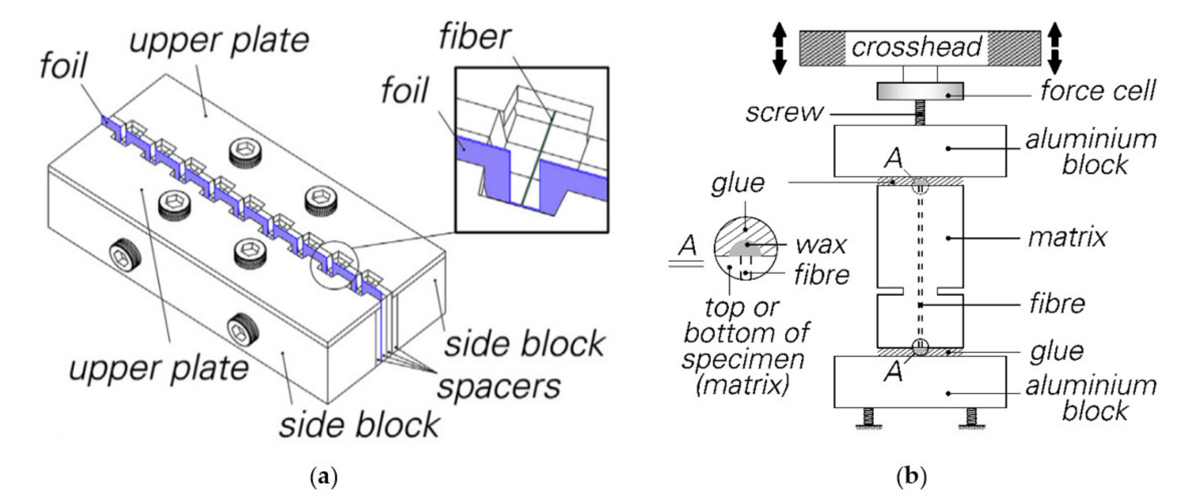
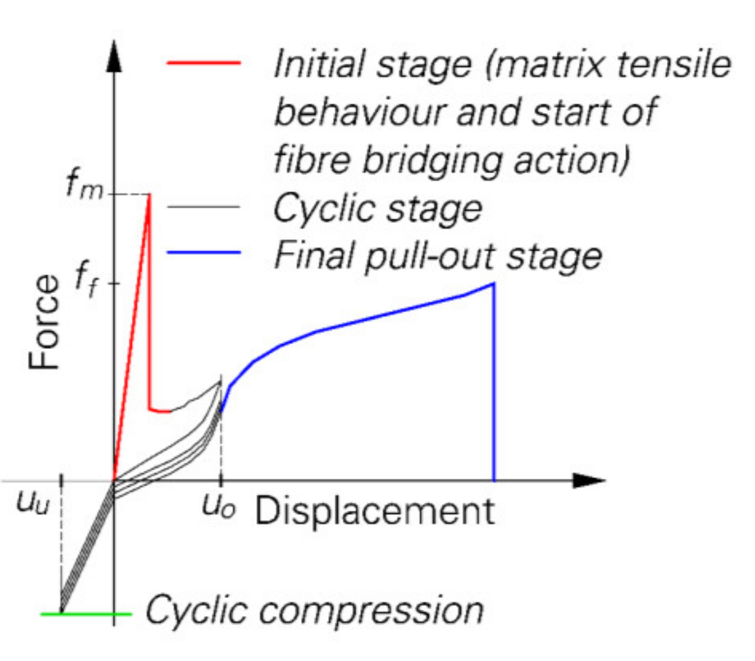
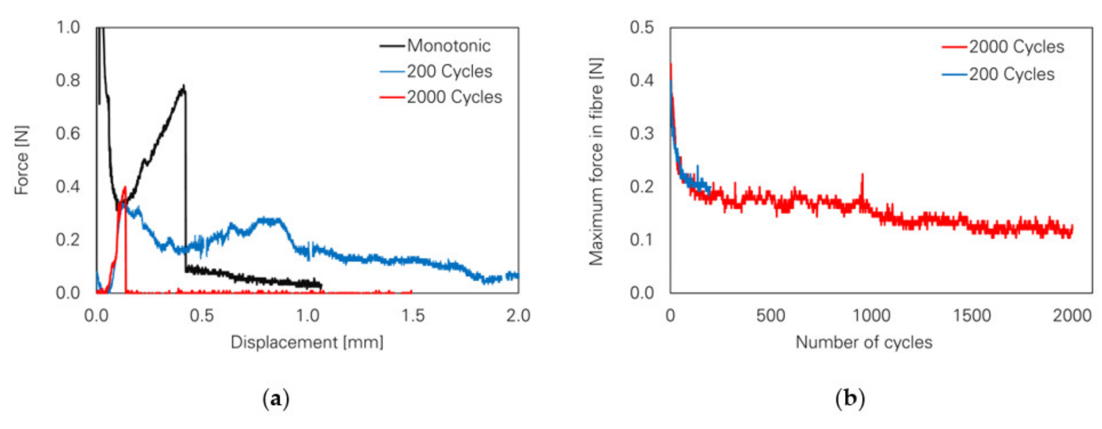
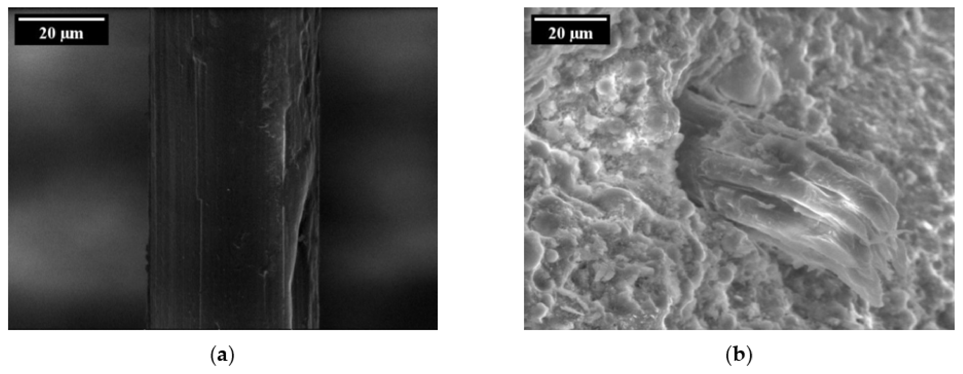
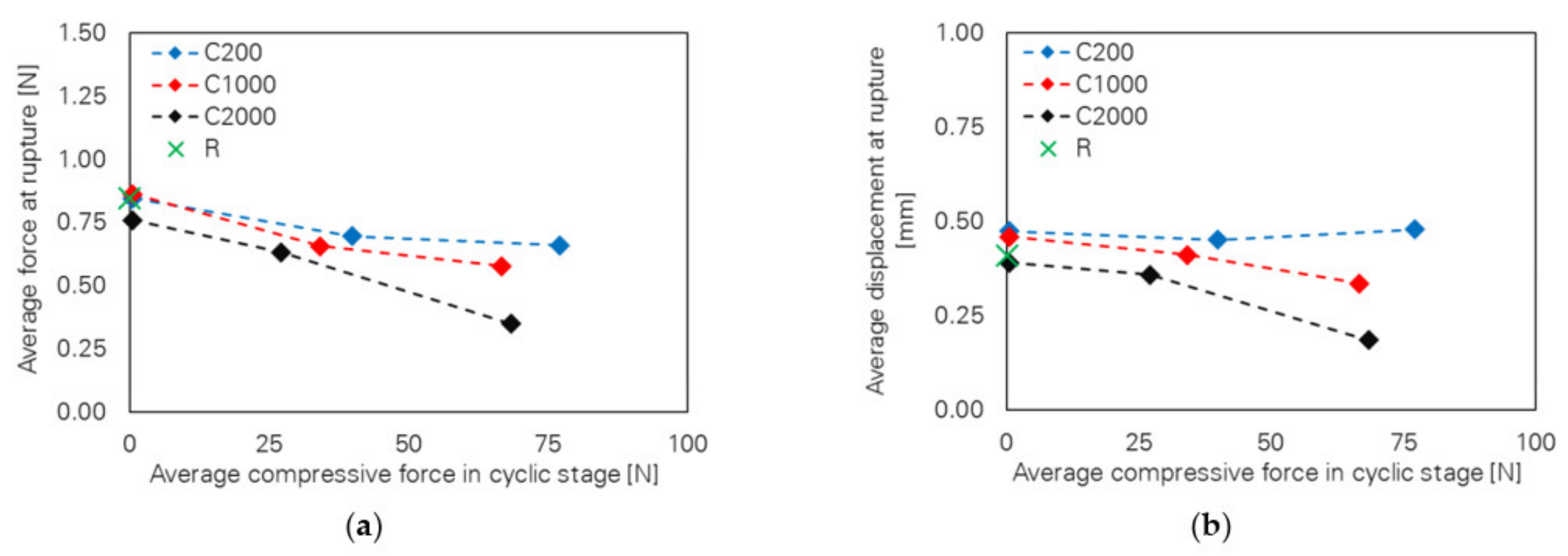
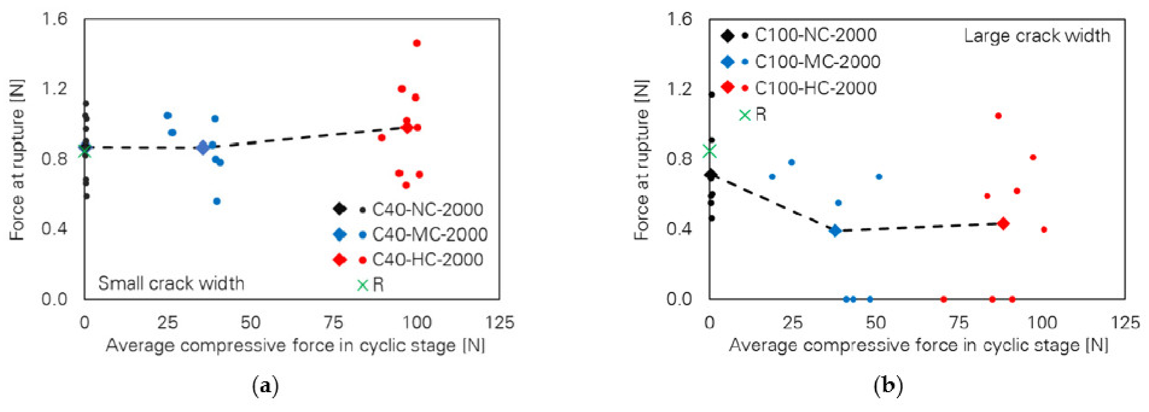
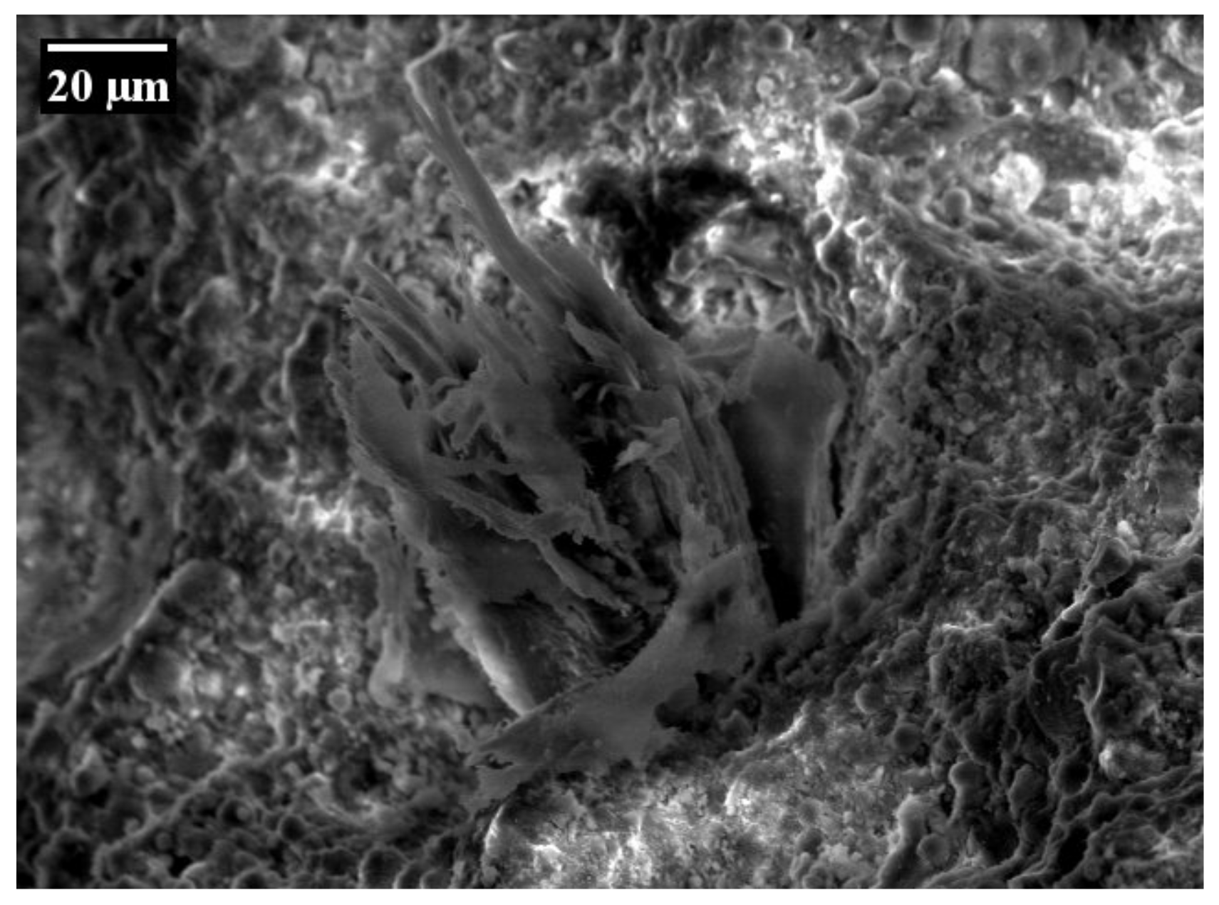
2.2. Experiments
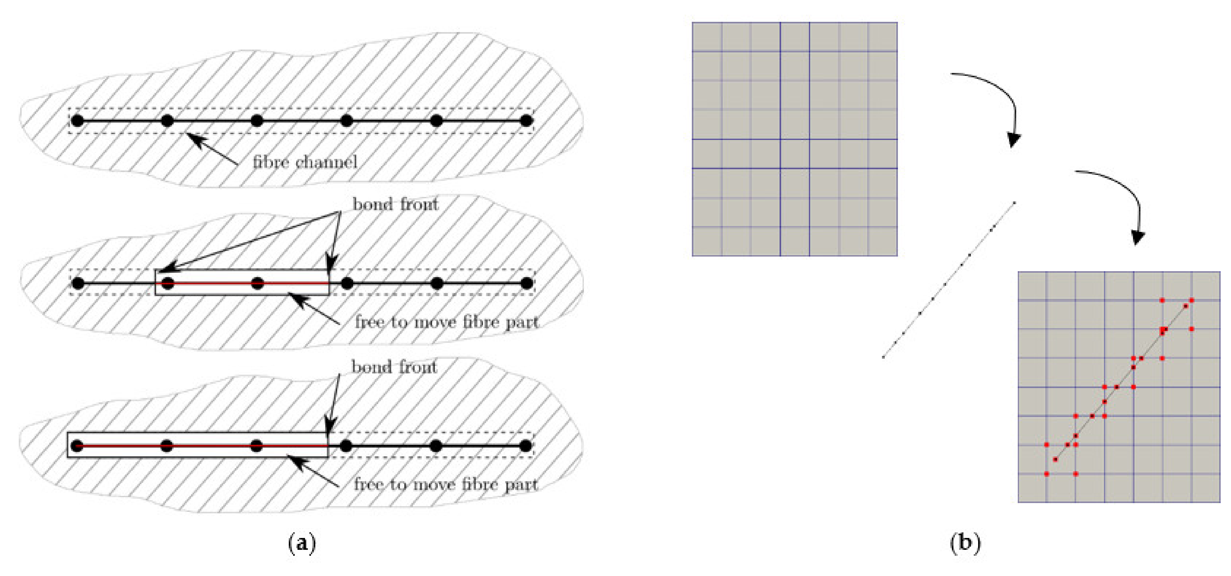
2.3. Numerical Methods
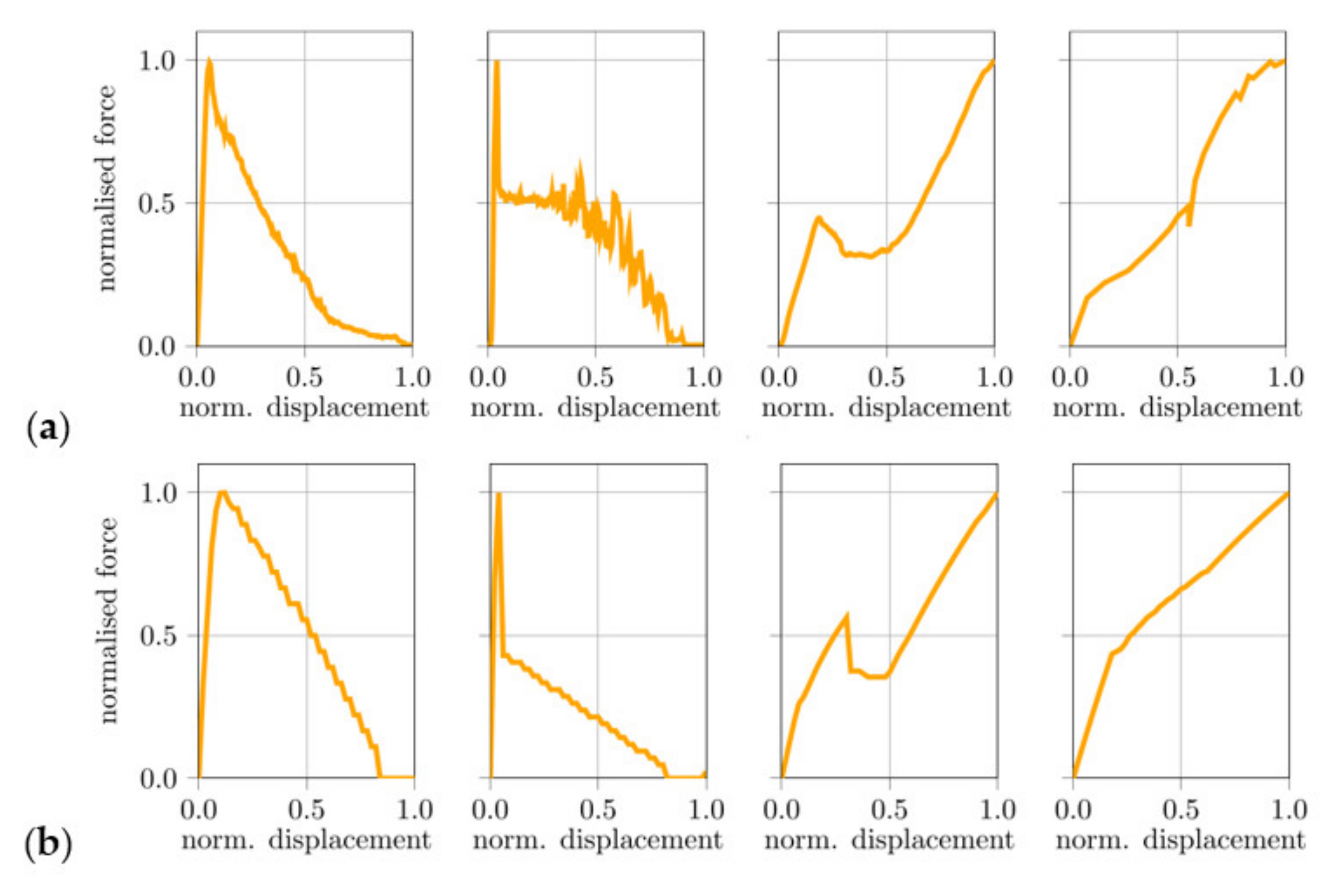
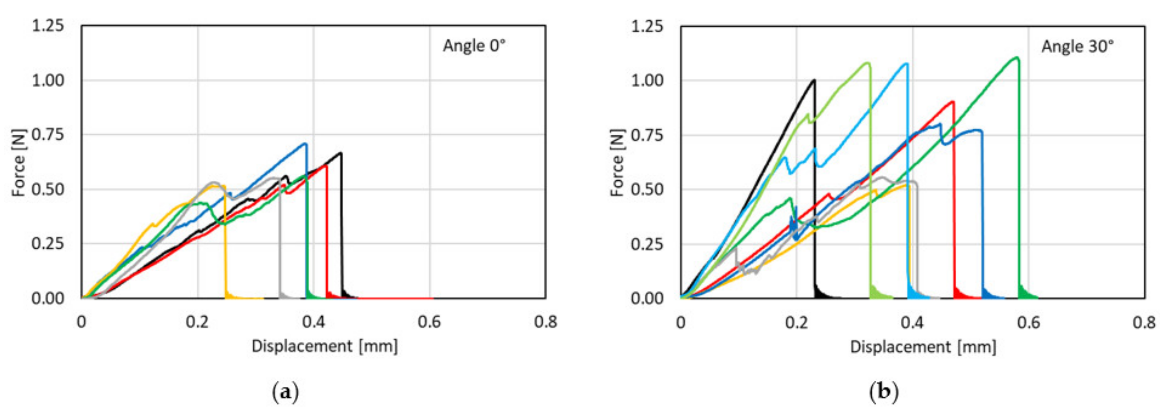
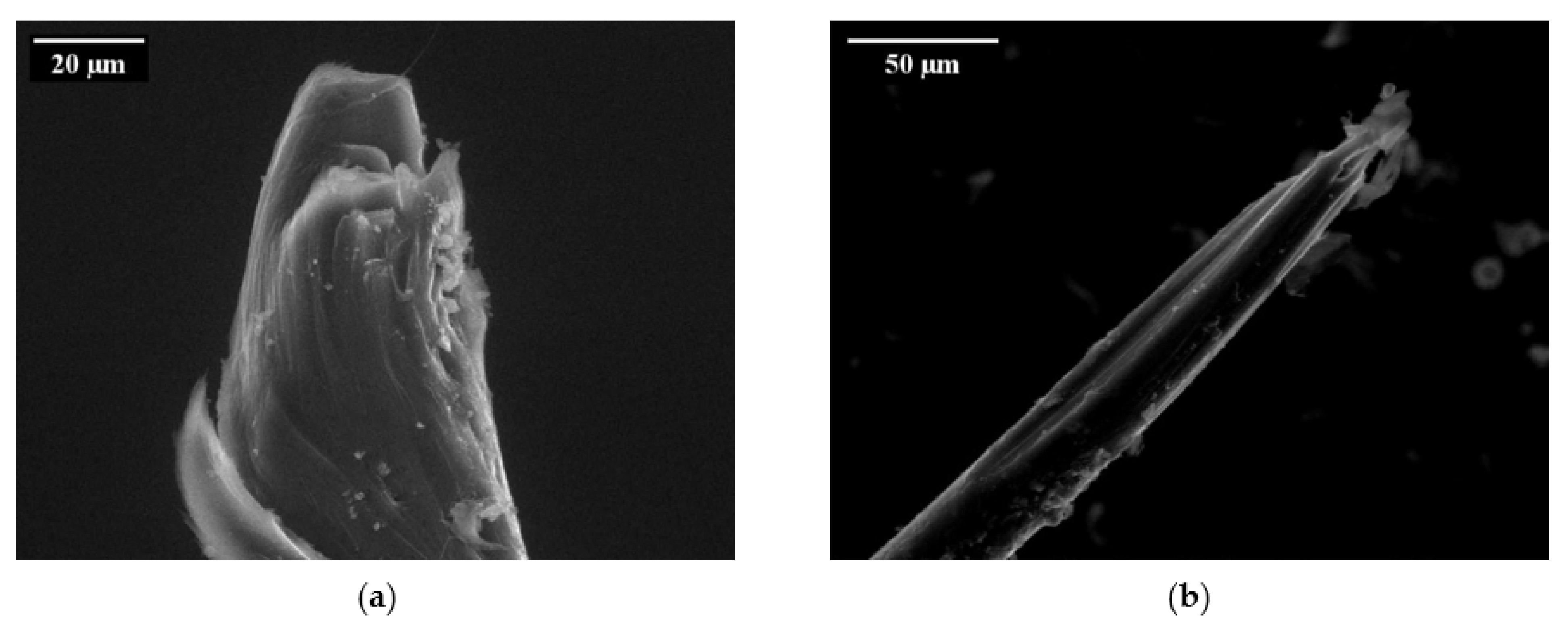
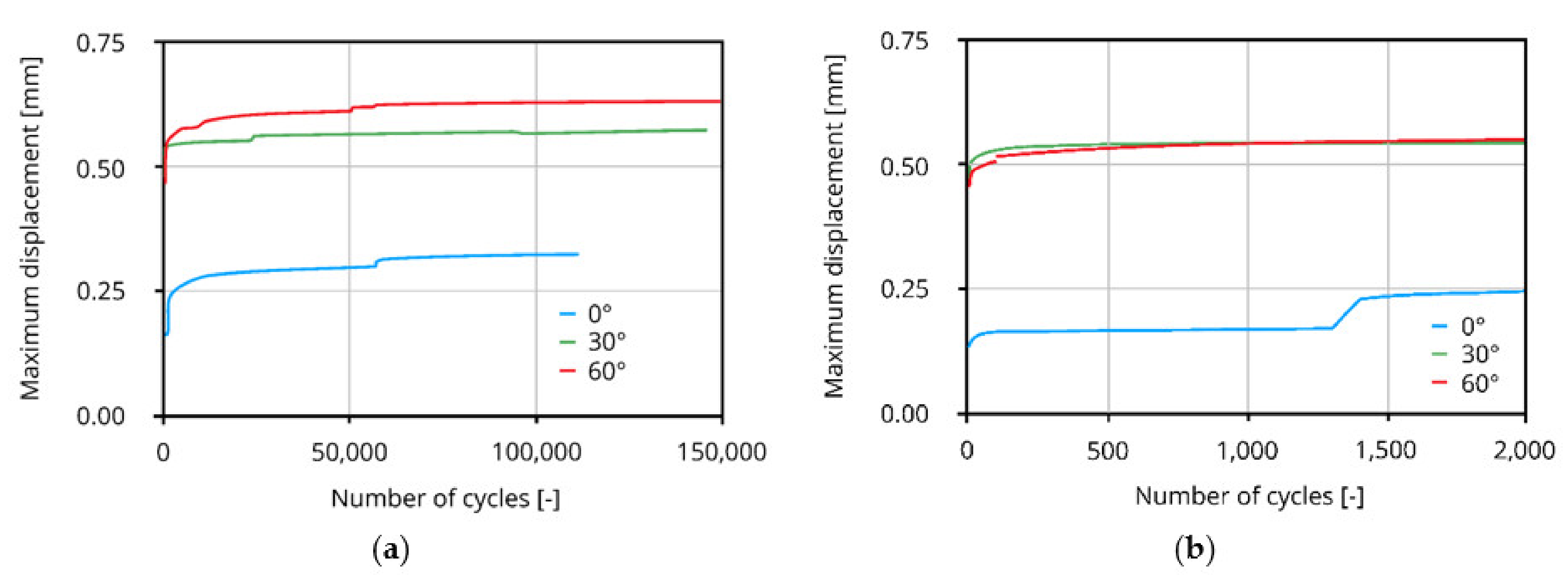
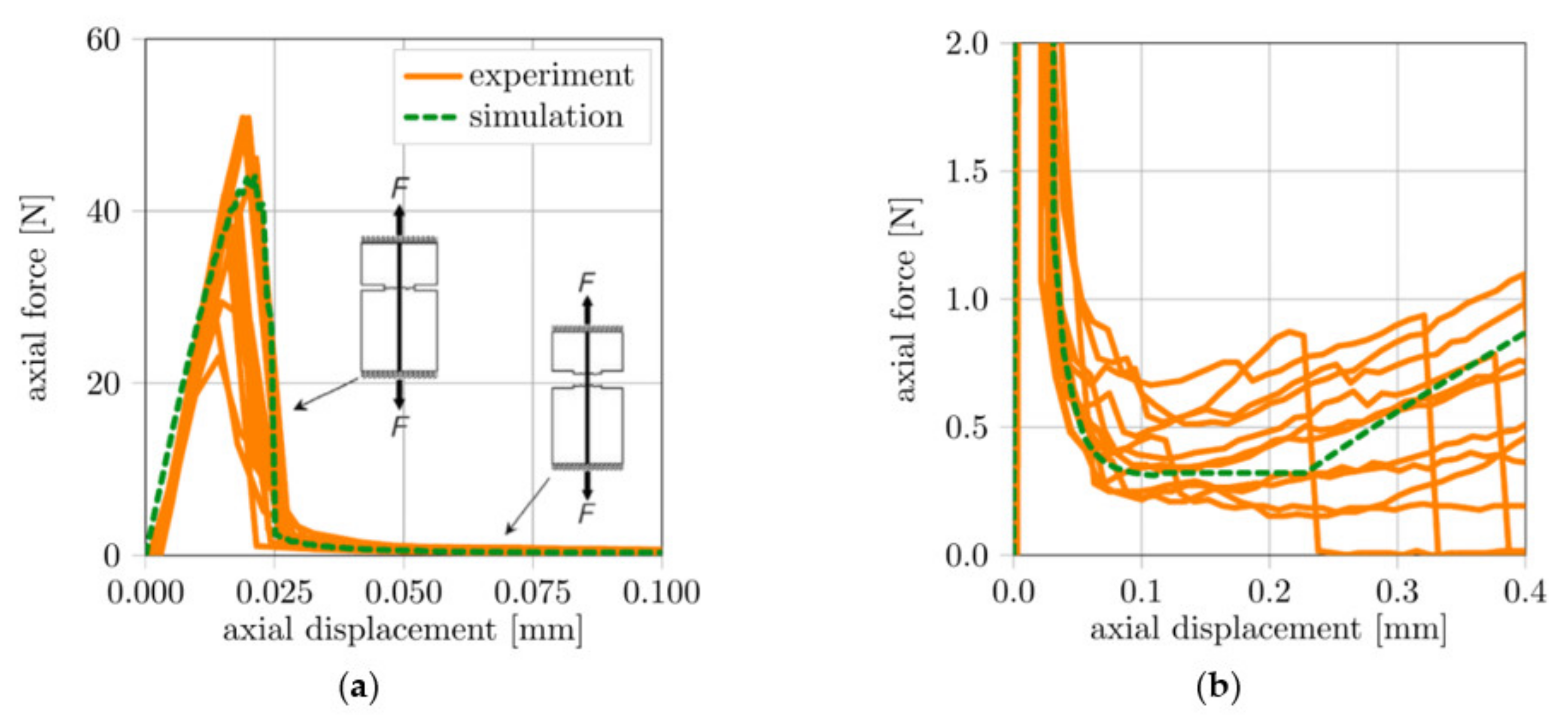
3. Results and Discussion
4. Conclusions
Author Contributions
Funding
Conflicts of Interest
References
- Li, V. From Micromechanics to structural engineering—The design of cementitious composites for civil engineering applications. J. Struct. Mech. Earthq. Eng. 1993, 10, 37–48. [Google Scholar]
- Yu, K.; Wang, Y.; Yu, J.; Xu, S. A strain-hardening cementitious composites with the tensile capacity up to 8%. Constr. Build. Mater. 2017, 137, 410–419. [Google Scholar] [CrossRef]
- Li, V.C.; Wang, S.; Wu, C. Tensile Strain-Hardening Behavior of Polyvinyl Alcohol Engineered Cementitious Composite (PVA-ECC). ACI Mater. J. 2001, 98. [Google Scholar] [CrossRef]
- Curosu, I. Influence of Fiber Type and Matrix Composition on the Tensile Behavior of Strain-Hardening Cement-Based Composites (SHCC) under Impact Loading. Ph.D. Thesis, Technische Universität Dresden, Dresden, Germany, 2017. [Google Scholar]
- Li, V.C.; Leung, C.K.Y. Steady-state and multiple cracking of short random fiber composites. J. Eng. Mech. 1992, 118, 2246–2264. [Google Scholar] [CrossRef] [Green Version]
- Heravi, A.; Mosig, O.; Tawfik, A.; Curbach, M.; Mechtcherine, V. An experimental investigation of the behavior of strain-hardening cement-based composites (SHCC) under impact compression and shear loading. Materials 2020, 13, 4514. [Google Scholar] [CrossRef]
- Curosu, I.; Mechtcherine, V.; Forni, D.; Cadoni, E. Performance of various strain-hardening cement-based composites (SHCC) subject to uniaxial impact tensile loading. Cem. Concr. Res. 2017, 102, 16–28. [Google Scholar] [CrossRef]
- Mechtcherine, V.; Millon, O.; Butler, M.; Thoma, K. Mechanical behaviour of strain hardening cement-based composites under impact loading. Cem. Concr. Res. 2011, 33, 1–11. [Google Scholar] [CrossRef]
- Heravi, A.A.; Smirnova, O.; Mechtcherine, V. Effect of strain rate and fiber type on tensile behavior of high-strength strain-hardening cement-based composites (HS-SHCC). In Strain-Hardening Cement-Based Composites; Mechtcherine, V., Slowik, V., Kabele, P., Eds.; RILEM Bookseries; Springer: Dordrecht, The Netherlands, 2018; Volume 15, pp. 266–274. ISBN 978-94-024-1193-5. [Google Scholar]
- Fukuyama, H.; Suwada, H. Experimental Response of HPFRCC dampers for structural control. ACT 2003, 1, 317–326. [Google Scholar] [CrossRef] [Green Version]
- Kotze, M.; Van Rooyen, G.C.; Van Zijl, G.P.A.G. Retrofitting unreinforced masonry buildings with a strain-hardening cement-based composite to enhance seismic resistance. In Proceedings of the 10th International Conference on Fracture Mechanics of Concrete and Concrete Structures, IA-FraMCoS, Bayonne, France, 24–26 June 2019. [Google Scholar]
- Müller, S.; Mechtcherine, V. Use of strain-hardening cement-based composites (SHCC) for retrofitting. MATEC Web Conf. 2018, 199, 09006. [Google Scholar] [CrossRef]
- Li, V.C.; Horii, H.; Kabele, P.; Kanda, T.; Lim, Y.M. Repair and retrofit with engineered cementitious composites. Eng. Fract. Mech. 2000, 65, 317–334. [Google Scholar] [CrossRef] [Green Version]
- Müller, S.; Mechtcherine, V. High-Cycle Fatigue of Strain-Hardening Cement-Based Composites (SHCC). In Proceedings of the SHCC3—3rd International RILEM Conference on Strain Hardening Cementitious Composites, Dordrecht, The Netherlands, 3–5 November 2014; pp. 137–144. [Google Scholar]
- Müller, S.; Mechtcherine, V. Behaviour of Strain-Hardening Cement-Based Composites (SHCC) Under Force-Controlled Cyclic Loading. In Proceedings of the 9th International Conference on Fracture Mechanics of Concrete and Concrete Structures, Berkeley, CA, USA, 29 May 2016. [Google Scholar]
- Müller, S.; Mechtcherine, V. Fatigue behaviour of strain-hardening cement-based composites (SHCC). Cem. Concr. Res. 2017, 92, 75–83. [Google Scholar] [CrossRef]
- Jun, P.; Mechtcherine, V. Behaviour of Strain-Hardening Cement-Based Composites (SHCC) under Monotonic and Cyclic Tensile Loading—Part 1—Experimental Investigations. Cem. Concr. Compos. 2010, 32, 801–809. [Google Scholar] [CrossRef]
- Fischer, G.; Li, V.C. Effect of matrix ductility on deformation behavior of steel-reinforced ECC flexural members under reversed cyclic loading conditions. ACI Struct. J. 2002, 99, 781–790. [Google Scholar] [CrossRef]
- Fischer, G.; Li, V.C. Deformation behavior of fiber-reinforced polymer reinforced engineered cementitious composite (ECC) flexural members under reversed cyclic loading conditions. ACI Struct. J. 2003, 100, 25–35. [Google Scholar] [CrossRef] [Green Version]
- Said, S.H.; Abdul Razak, H. Structural behavior of RC engineered cementitious composite (ECC) exterior beam–Column joints under reversed cyclic loading. Constr. Build. Mater. 2016, 107, 226–234. [Google Scholar] [CrossRef]
- Wu, C.; Pan, Z.; Su, R.K.L.; Leung, C.K.Y.; Meng, S. Seismic behavior of steel reinforced ECC columns under constant axial loading and reversed cyclic lateral loading. Mater. Struct. 2017, 50, 78. [Google Scholar] [CrossRef]
- Ranjbarian, M.; Mechtcherine, V. A novel test setup for the characterization of bridging behaviour of single microfibres embedded in a mineral-based matrix. Cem. Concr. Compos. 2018, 92, 92–101. [Google Scholar] [CrossRef]
- Ranjbarian, M.; Mechtcherine, V. Influence of loading parameters in cyclic tension-compression regime on crack-bridging behaviour of PVA microfibres embedded in cement-based matrix. Constr. Build. Mater. 2019, 228, 116760. [Google Scholar] [CrossRef]
- Ranjbarian, M.; Mechtcherine, V. Cyclic DAMAGE to PVA Microfibre Embedded in Cementitious Matrix in Alternating Tension-Compression Regime. In Proceedings of the FRC2018: Fibre Reinforced Concrete: From Design to Structural Applications, Desenzano, Lake Garda, Italy, 28–30 June 2018; Volume 343, pp. 321–329. [Google Scholar]
- Ranjbarian, M.; Mechtcherine, V. Pilot Investigation into Crack Bridging Behaviour of Different Types of High-Performance Microfibres under Reversed Tension-Compression Loading. In Proceedings of the fib Symposium 2019, Concrete—Innovations in Materials, Design and Structures, Kraków, Poland, 27–29 May 2019; pp. 121–128. [Google Scholar]
- Ranjbarian, M.; Ma, X.; Mechtcherine, V. Influence of crack width in alternating tension–Compression regimes on crack-bridging behaviour and degradation of PVA microfibres embedded in cement-based matrix. Materials 2020, 13, 4189. [Google Scholar] [CrossRef] [PubMed]
- Ranjbarian, M.; Mechtcherine, V.; Storm, J.; Kaliske, M. Influence of fibre orientation on pull-out behaviour of PVA microfibre embedded in cement-based matrix under monotonic and cyclic loading. In Advances in Engineering Materials, Structures and Systems: Innovations, Mechanics and Applications; Zingoni, A., Ed.; CRC Press: Boca Raton, FL, USA, 2019; pp. 1433–1438. ISBN 978-0-429-42650-6. [Google Scholar]
- Ranjbarian, M.; Mechtcherine, V.; Zhang, Z.; Curosu, I.; Storm, J.; Kaliske, M. Locking front model for pull-out behaviour of PVA microfibre embedded in cementitious matrix. Cem. Concr. Compos. 2019, 103, 318–330. [Google Scholar] [CrossRef]
- Müller, S.; Ranjbarian, M.; Mechtcherine, V. Fatigue behavior of strain-hardening cement-based composites—From the single fiber level to real-scale application. Struct. Concr. 2019, 20, 1231–1242. [Google Scholar] [CrossRef]
- Carrara, P.; Ambati, M.; Alessi, R.; Lorenzis, L.D. A Framework to model the fatigue behavior of brittle materials based on a variational phase-field approach. Comput. Methods Appl. Mech. Eng. 2020, 361, 112731. [Google Scholar] [CrossRef]
- Schreiber, C.; Müller, R.; Kuhn, C. Phase field simulation of fatigue crack propagation under complex load situations. Arch. Appl. Mech. 2021, 91, 563–577. [Google Scholar] [CrossRef]
- Loew, P.J.; Poh, L.H.; Peters, B.; Beex, L.A.A. Accelerating fatigue simulations of a phase-field damage model for rubber. Comput. Methods Appl. Mech. Eng. 2020, 370, 113247. [Google Scholar] [CrossRef]
- Ambrosio, L.; Tortorelli, V.M. Approximation of functional depending on jumps by elliptic functional via T-convergence. Commun. Pure Appl. Math. 1990, 43, 999–1036. [Google Scholar] [CrossRef]
- Bach, A.; Marziani, R.; Zeppieri, C.I. Γ-Convergence and Stochastic homogenisation of singularly-perturbed elliptic functionals. arXiv 2021, arXiv:2102.09872. [Google Scholar]
- Wu, J.-Y.; Huang, Y.; Nguyen, V.P. On the BFGS monolithic algorithm for the unified phase field damage theory. Comput. Methods Appl. Mech. Eng. 2020, 360, 112704. [Google Scholar] [CrossRef]
- Cao, Y.J.; Shen, W.Q.; Shao, J.F.; Wang, W. A novel FFT-based phase field model for damage and cracking behavior of heterogeneous materials. Int. J. Plast. 2020, 133, 102786. [Google Scholar] [CrossRef]
- Storm, J.; Supriatna, D.; Kaliske, M. The concept of representative crack elements for phase-field fracture: Anisotropic elasticity and thermo-elasticity. Int. J. Numer. Methods Eng. 2020, 121, 779–805. [Google Scholar] [CrossRef]
- Yin, B.; Storm, J.; Kaliske, M. Viscoelastic phase-field fracture using the framework of representative crack elements. Int. J. Fract. 2021. [Google Scholar] [CrossRef]
- Storm, J.; Yin, B.; Kaliske, M. The concept of representative crack elements (RCE) for phase-field fracture—Non-linear materials and finite deformations. 2021; (submitted). [Google Scholar]
- Storm, J.; Yin, B.; Kaliske, M. the concept of representative crack elements (RCE) for phase-field fracture—Transient thermo-mechanics. 2021; (submitted). [Google Scholar]
- Kaliske, M.; Rothert, H. Formulation and implementation of three-dimensional viscoelasticity at small and finite strains. Comput. Mech. 1997, 19, 228–239. [Google Scholar] [CrossRef]
- Storm, J.; Ranjbarian, M.; Mechtcherine, V.; Scheffler, C.; Kaliske, M. Modelling of fibre-reinforced composites via fibre super-elements. Theor. Appl. Fract. Mech. 2019, 103, 102294. [Google Scholar] [CrossRef]
- Ranjbarian, M. Crack-Bridging Behaviour of Polymer Fibers in Strain-Hardening Cement-Based Composites (SHCC) Subject to Alternating Tension-Compression Cyclic Loading. Ph.D. Thesis, Technische Universität Dresden, Dresden, Germany, 2020. [Google Scholar]


| Cement CEM I 42.5 R-HS | Fly Ash | Water | Quartz Sand 0.06/0.2 | Superplasticizer | Viscosity Agent |
|---|---|---|---|---|---|
| 505 | 621 | 338 | 536 | 10 | 4.8 |
| Nominal Diameter [µm] | Tensile Strength [MPa] | Young’s Modulus [GPa] | Strain Capacity [-] | Density [g/cm3] |
|---|---|---|---|---|
| 40 | 1600 | 40 | 0.07 | 1.3 |
Publisher’s Note: MDPI stays neutral with regard to jurisdictional claims in published maps and institutional affiliations. |
© 2021 by the authors. Licensee MDPI, Basel, Switzerland. This article is an open access article distributed under the terms and conditions of the Creative Commons Attribution (CC BY) license (https://creativecommons.org/licenses/by/4.0/).
Share and Cite
Junger, D.; Storm, J.; Müller, S.; Kaliske, M.; Mechtcherine, V. Increasing the Fatigue Resistance of Strain-Hardening Cement-Based Composites (SHCC) by Experimental-Virtual Multi-Scale Material Design. Materials 2021, 14, 5634. https://doi.org/10.3390/ma14195634
Junger D, Storm J, Müller S, Kaliske M, Mechtcherine V. Increasing the Fatigue Resistance of Strain-Hardening Cement-Based Composites (SHCC) by Experimental-Virtual Multi-Scale Material Design. Materials. 2021; 14(19):5634. https://doi.org/10.3390/ma14195634
Chicago/Turabian StyleJunger, Dominik, Johannes Storm, Steffen Müller, Michael Kaliske, and Viktor Mechtcherine. 2021. "Increasing the Fatigue Resistance of Strain-Hardening Cement-Based Composites (SHCC) by Experimental-Virtual Multi-Scale Material Design" Materials 14, no. 19: 5634. https://doi.org/10.3390/ma14195634