
A 3D Finite Element Analysis Model of Single Implant-Supported Prosthesis under Dynamic Impact Loading for Evaluation of Stress in the Crown, Abutment and Cortical Bone Using Different Rehabilitation Materials

 , ,
, ,  , and
, and
Abstract
:
1. Introduction
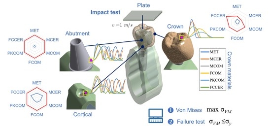
2. Materials and Methods
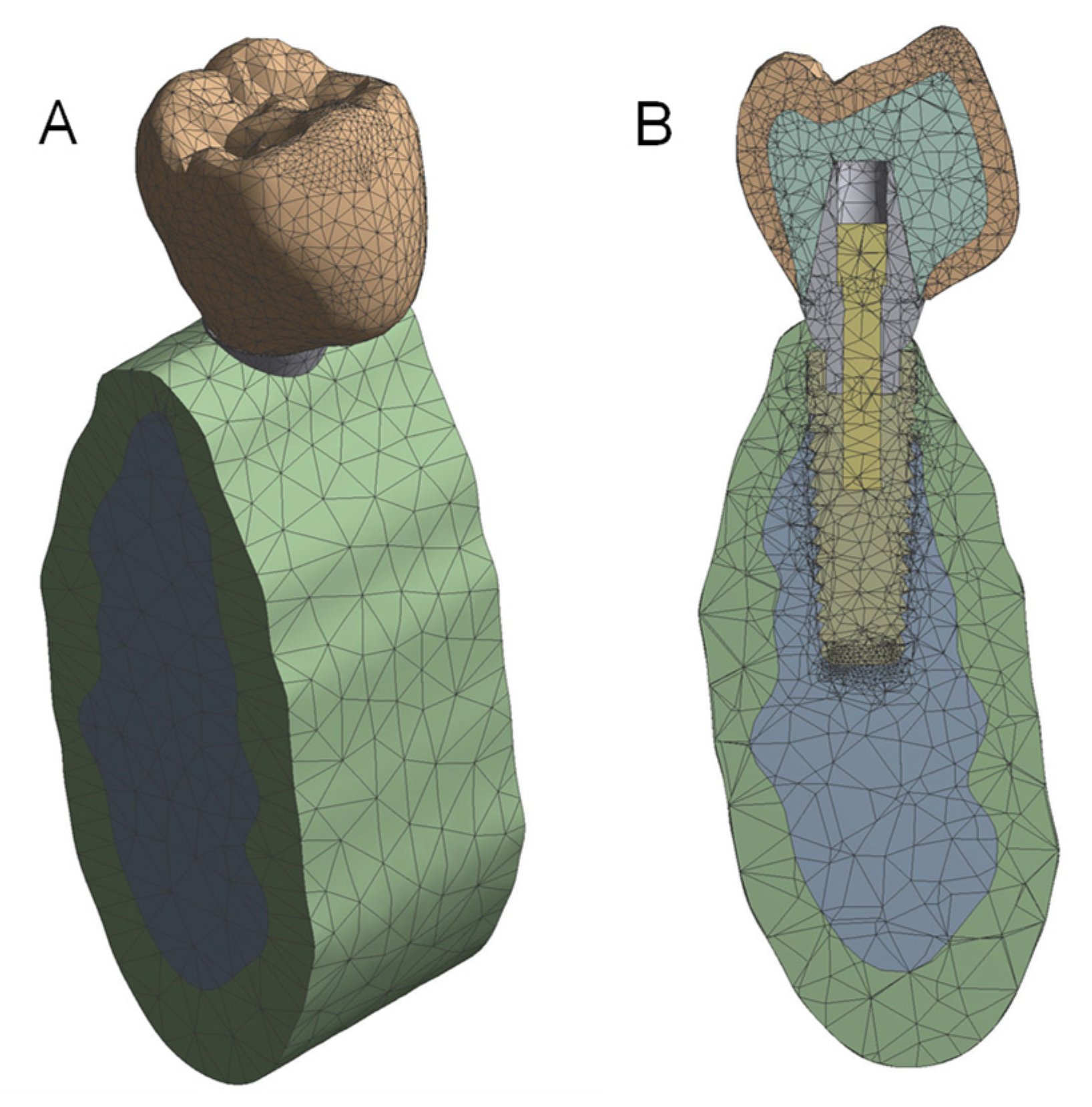
2.1. The Whole Implant Model
2.1.1. The Crown
2.1.2. The Abutment and Fixation Screw
2.1.3. The Implant
2.1.4. The Mandible
2.1.5. The Plate
2.2. Material Properties
2.3. Numerical Methods
2.3.1. Mesh Definition
2.3.2. Simulation Time
3. Results
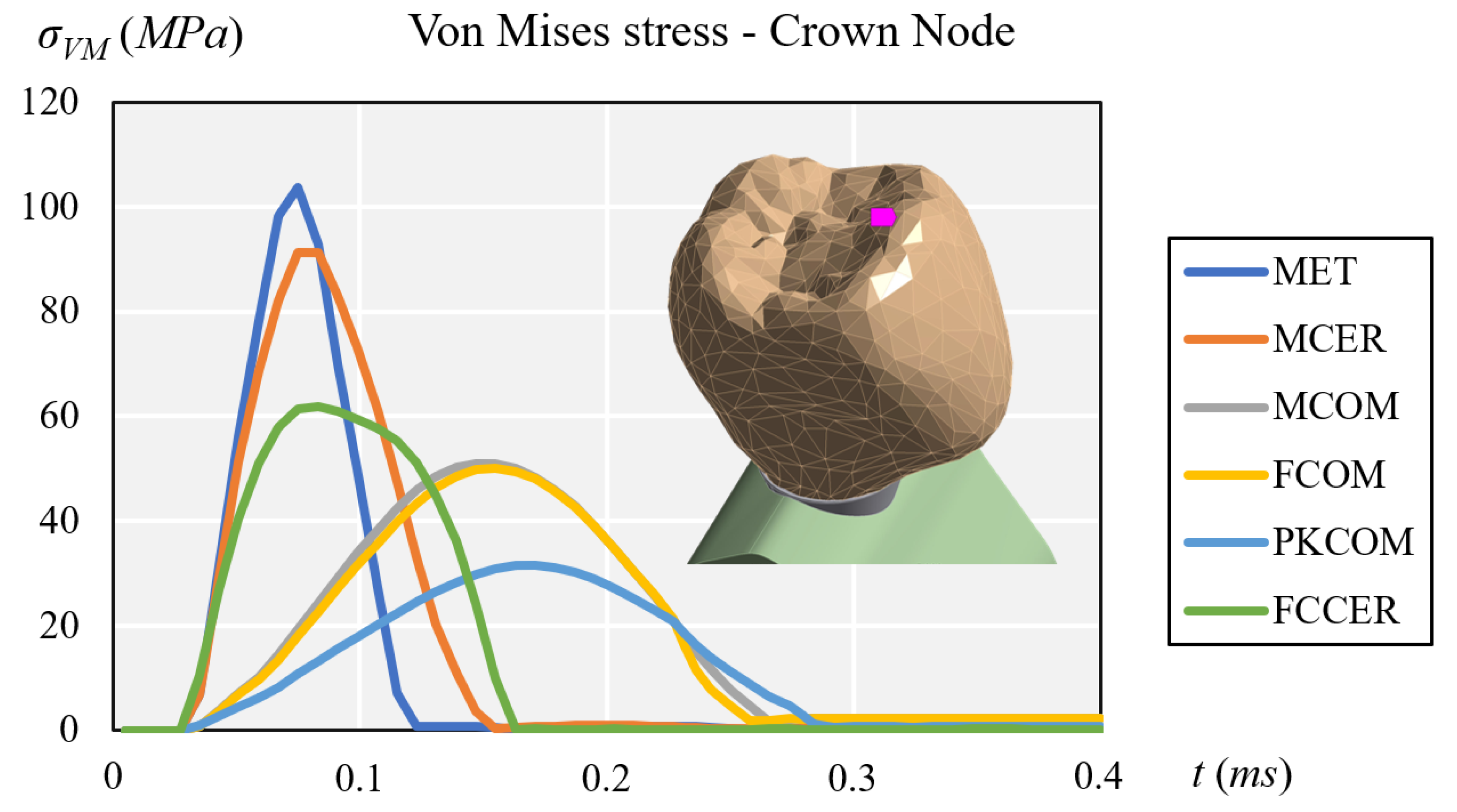
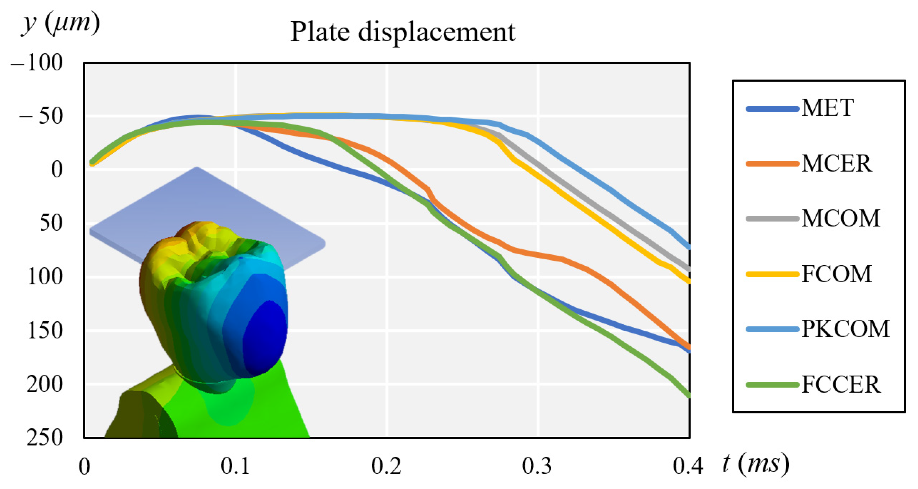
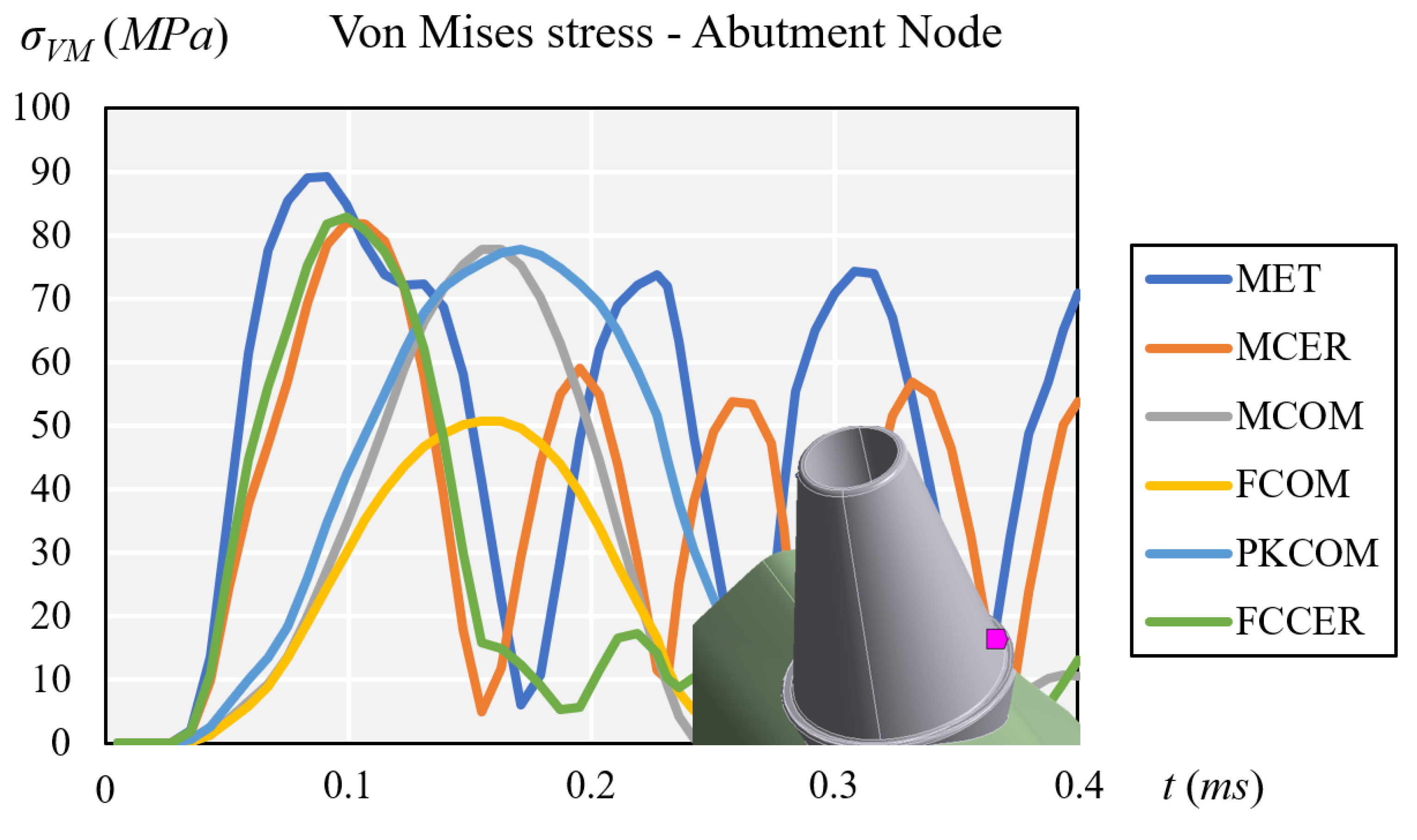
3.1. Stress Results
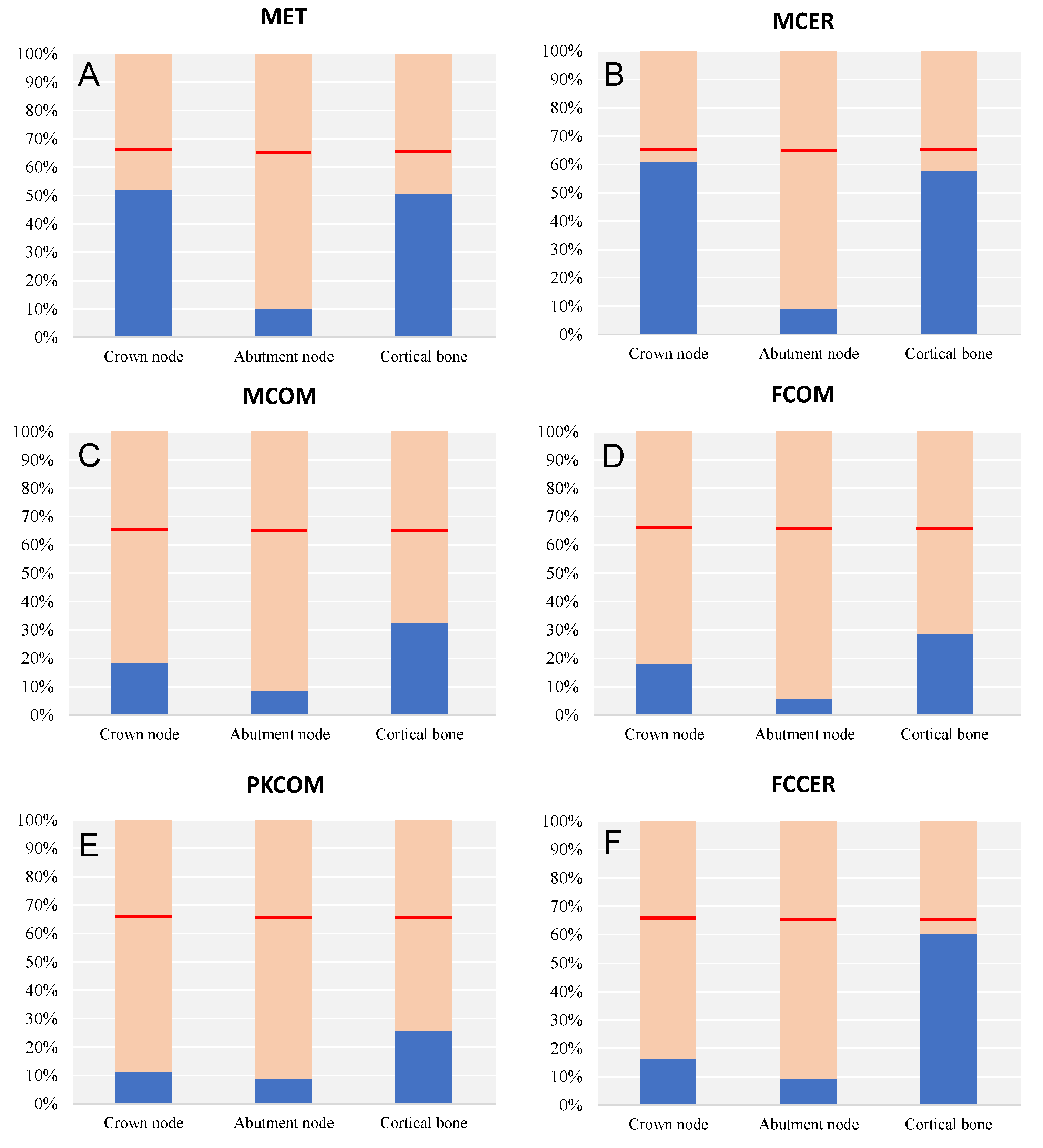
3.2. Elastic Failure Test
4. Conclusions
Author Contributions
Funding
Institutional Review Board Statement
Informed Consent Statement
Data Availability Statement
Acknowledgments
Conflicts of Interest
Abbreviations
| MET | CoCr Metal |
| MCOM | CoCr Metal-Composite |
| MCER | CoCr Metal-Ceramic |
| FCOM | Carbon Fiber-Composite |
| PKCOM | PEEK-Composite |
| FCCER | Carbon Fiber-Ceramic |
References
- Jemt, T.; Lekholm, U.; Adell, R. Osseointegrated implants in the treatment of partially edentulous patients: A preliminary study on 876 consecutively placed fixtures. Int. J. Oral Maxillofac. Implant 1989, 4, 211–217. [Google Scholar]
- Adell, R.; Eriksson, B.; Lekholm, U.; Branemark, P.I.; Jemt, T. Long-term follow-up study of osseointegrated implants in the treatment of totally edentulous jaws. Int. J. Oral Maxillofac. Implant 1990, 5, 347–359. [Google Scholar]
- Roberts, H.W.; Berzins, D.W.; Moore, B.K.; Charlton, D.G. Metal-ceramic alloys in dentistry: A review. J Prosthodont 2009, 18, 188–194. [Google Scholar] [CrossRef] [PubMed]
- Wataha, J.C. Biocompatibility of dental casting alloys: A review. J. Prosthet. Dent. 2000, 83, 223–234. [Google Scholar] [CrossRef]
- Tuna, S.H.; Pekmez, N.O.; Keyf, F.; Canli, F. The electrochemical propierties of four dental casting suprastructure alloys coupled with titanium implants. J. Appl. Oral Sci. 2009, 17, 467–475. [Google Scholar] [CrossRef]
- Bagegni, A.; Abou-Ayash, S.; Rucker, G.; Algarny, A.; Att, W. The influence of prosthetic material on implant and prosthetic survival of implant-supported fixed complete dentures: A systematic review and meta-analysis. J. Prosthodont. Res. 2019, 63, 251–265. [Google Scholar] [CrossRef]
- Hu, M.L.; Lin, H.; Zhang, Y.D.; Han, J.M. Comparison of technical, biological, and esthetic parameters of ceramic and met-al-ceramic implant-supported fixed dental prostheses: A systematic review and meta-analysis. J. Prosthet. Dent. 2019, 124, 26–35. [Google Scholar] [CrossRef] [PubMed]
- Le, M.; Papia, E.; Larsson, C. The clinical success of tooth- and implant-supported zirconia-based fixed dental prostheses. A systematic review. J. Oral Rehabil. 2015, 42, 467–480. [Google Scholar] [CrossRef] [PubMed]
- Deany, I.L. Recent advances in ceramics for dentistry. Crit Rev. Oral Biol. Med. 1996, 7, 134–143. [Google Scholar]
- Yamaguchi, S.; Okada, C.; Watanabe, Y.; Watanabe, M.; Hattori, Y. Analysis of masticatory muscle coordination during unilateral single-tooth clenching using muscle functional magnetic resonance imaging. J. Oral Rehabil. 2018, 45, 9–16. [Google Scholar] [CrossRef] [PubMed]
- Moss, R.A.; Villarosa, G.A.; Cooley, J.E.; Lombardo, T.W. Masticatory muscle activity as a function of parafunctional, active and passive oral behavioural patterns. J. Oral Rehabil. 1987, 14, 361–370. [Google Scholar] [CrossRef]
- Takeda, H.; Saitoh, K. Impact of proprioception during the oral phase on initiating the swallowing reflex. Laryngoscope 2016, 126, 1595–1599. [Google Scholar] [CrossRef]
- Safari, A.; Jowkar, Z.; Farzin, M. Evaluation of the relationship between bruxism and premature occlusal contacts. J. Contemp. Dent. Pract. 2013, 14, 616–621. [Google Scholar] [CrossRef] [PubMed]
- Van der Bilt, A.; Engelen, L.; Pereira, L.J.; van der Glas, H.W.; Abbink, J.H. Oral physiology and mastication. Physiol. Behav. 2006, 89, 22–27. [Google Scholar] [CrossRef] [PubMed]
- Trulsson, M. Force encoding by human periodontal mechanoreceptors during mastication. Arch. Oral Biol. 2007, 52, 357–360. [Google Scholar] [CrossRef] [PubMed]
- Cicciu, M.; Cervino, G.; Milone, D.; Risitano, G. FEM Investigation of the Stress Distribution over Mandibular Bone Due to Screwed Overdenture Positioned on Dental Implants. Materials 2018, 11, 1512. [Google Scholar] [CrossRef] [PubMed] [Green Version]
- Menini, M.; Conserva, E.; Tealdo, T.; Bevilacqua, M.; Pera, F.; Signori, A.; Pera, P. Shock Absorption Capacity of Restorative Materials for Dental Implant Prostheses: An In Vitro Study. Int. J. Prosthodont. 2013, 26, 549–556. [Google Scholar] [CrossRef] [PubMed] [Green Version]
- Cehreli, M.; Duyck, J.; De Cooman, M.; Puers, R.; Naert, I. Implant design and interface force transfer. Clin. Oral Implant. Res. 2004, 15, 249–257. [Google Scholar] [CrossRef]
- Gracis, S.E.; Nicholls, J.I.; Chalupnik, J.D.; Yuodelis, R.A. Shock-absorbing behavior of five restorative materials used on im-plants. Int. J. Prosthodont. 1991, 4, 282–291. [Google Scholar] [PubMed]
- Menini, M.; Conserva, E.; Tealdo, T.; Bevilacqua, M.; Pera, F.; Ravera, G.; Pera, P. The use of a masticatory robot to analyze the shock absorption capacity of different restorative materials for implant prosthesis. J. Biol. Res. Boll. Della Soc. Ital. Biol. Sper. 2011, 84, 118–119. [Google Scholar] [CrossRef]
- Magne, P.; Silva, M.; Oderich, E.; Boff, L.L.; Enciso, R. Damping behavior of implant-supported restorations. Clin. Oral Implant. Res. 2011, 24, 143–148. [Google Scholar] [CrossRef]
- Sevimay, M.; Turhan, F.; Kilicarslan, M.A.; Eskitascioglu, G. Three-dimensional finite element analysis of the effect of differ-ent bone quality on stress distribution in an implant-supported crown. J. Prosthet. Dent. 2005, 93, 227–234. [Google Scholar] [CrossRef] [PubMed]
- Mizusawa, K.; Shin, C.; Okada, D.; Ogura, R.; Komada, W.; Saleh, O.; Huang, L.; Miura, H. The investigation of the stress distribution in abutment teeth for connected crowns. J. Dent. Sci. 2021, 16, 929–936. [Google Scholar] [CrossRef] [PubMed]
- Kaleli, N.; Sarac, D.; Külünk, S.; Öztürk, Ö. Effect of different restorative crown and customized abutment materials on stress distribution in single implants and peripheral bone: A three-dimensional finite element analysis study. J. Prosthet. Dent. 2018, 119, 437–445. [Google Scholar] [CrossRef]
- Geramizadeh, M.; Katoozian, H.; Amid, R.; Kadkhodazadeh, M. Static, Dynamic, and Fatigue Finite Element Analysis of Dental Implants with Different Thread Designs. J. Autom. Inf. Sci. 2016, 26, 347–355. [Google Scholar] [CrossRef]
- Geramizadeh, M.; Katoozian, H.; Amid, R.; Kadkhodazadeh, M. Finite Element Analysis of Dental Implants with and without Microthreads under Static and Dynamic Loading. J. Autom. Inf. Sci. 2017, 27, 25–35. [Google Scholar] [CrossRef]
- Karpov, E.G.; Danso, L.A.; Klein, J.T. Anomalous strain energy transformation pathways in mechanical metamaterials. Proc. Math. Phys. Eng. Sci. 2019, 475, 20190041. [Google Scholar] [CrossRef] [PubMed] [Green Version]
- King, H. Basic Finite Element Method Apllied to Injury Biomechanics; Academic Press: Cambridge, MA, USA, 2018; ISBN 9780128098318. [Google Scholar]
- Cantó-Navés, O.; Marimon, X.; Ferrer, M.; Cabratosa-Termes, J. Comparison between experimental digital image processing and numerical methods for stress analysis in dental implants with different restorative materials. J. Mech. Behav. Biomed. Mater. 2021, 113, 104092. [Google Scholar] [CrossRef] [PubMed]
- Menini, M.; Pesce, P.; Pera, F.; Barberis, F.; Lagazzo, A.; Bertola, L.; Pera, P. Biological and mechanical characterization of carbon fiber frameworks for dental implant applications. Mater. Sci. Eng. C 2017, 70, 646–655. [Google Scholar] [CrossRef]
- Erkmen, E.; Meriç, G.; Kurt, A.; Tunç, Y.; Eser, A. Biomechanical comparison of implant retained fixed partial dentures with fiber reinforced composite versus conventional metal frameworks: A 3D FEA study. J. Mech. Behav. Biomed. Mater. 2011, 4, 107–116. [Google Scholar] [CrossRef]
- Passaretti, A.; Petroni, G.; Miracolo, G.; Savoia, V.; Perpetuini, A.; Cicconetti, A. Metal free, full arch, fixed prosthesis for edentulous mandible rehabilitation on four implants. J. Prosthodont. Res. 2018, 62, 264–267. [Google Scholar] [CrossRef]
- Zaparolli, D.; Peixoto, R.F.; Pupim, D.; Macedo, A.P.; Toniollo, M.B.; Mattos, M.D.G.C.D. Photoelastic analysis of mandibular full-arch implant-supported fixed dentures made with different bar materials and manufacturing techniques. Mater. Sci. Eng. C 2017, 81, 144–147. [Google Scholar] [CrossRef]
- Pera, F.; Pesce, P.; Solimano, F.; Tealdo, T.; Pera, P.; Menini, M. Carbon fibre versus metal framework in full-arch immediate loading rehabilitations of the maxilla-a cohort clinical study. J. Oral Rehabil. 2017, 44, 392–397. [Google Scholar] [CrossRef]
- Segerstrom, S.; Ruyter, I.E. Effect of thermal cycling on flexural properties of carbon-graphite fiber-reinforced polymers. Dent. Mater. 2009, 25, 845–851. [Google Scholar] [CrossRef] [PubMed]
- Segerstrom, S.; Ruyter, I.E. Adhesion properties in systems of laminated pigmented polymers, carbon-graphite fiber composite framework and titanium surfaces in implant suprastructures. Dent. Mater. 2009, 25, 1169–1177. [Google Scholar] [CrossRef] [PubMed]
- Segerstrom, S.; Sandborgh-Englund, G.; Ruyter, E.I. Biological and physicochemical properties of carbon-graphite fi-bre-reinforced polymers intended for implant suprastructures. Eur. J. Oral Sci. 2011, 119, 246–252. [Google Scholar] [CrossRef] [PubMed]
- Muhsin, S.A.; Hatton, P.; Johnson, A.; Sereno, N.; Wood, D.J. Determination of Polyetheretherketone (PEEK) mechanical properties as a denture material. Saudi Dent. J. 2019, 31, 382–391. [Google Scholar] [CrossRef]
- Schwitalla, A.D.; Spintig, T.; Kallage, I.; Müller, W.-D. Pressure behavior of different PEEK materials for dental implants. J. Mech. Behav. Biomed. Mater. 2016, 54, 295–304. [Google Scholar] [CrossRef]
- Schwitalla, A.D.; Spintig, T.; Kallage, I.; Müller, W.-D. Flexural behavior of PEEK materials for dental application. Dent. Mater. 2015, 31, 1377–1384. [Google Scholar] [CrossRef]
- Gallucci, G.O.; Bernard, J.-P.; Bertosa, M.; Belser, U.C. Immediate loading with fixed screw-retained provisional restorations in edentulous jaws: The pickup technique. Int. J. Oral Maxillofac. Implant. 2004, 19, 524–533. [Google Scholar]
- Norton, M.R. An in vitro evaluation of the strength of an internal conical interface compared to a butt joint interface in implant design. Clin. Oral Implant. Res. 1997, 8, 290–298. [Google Scholar] [CrossRef]
- Tonella, B.P.; Pellizzer, E.P.; Ferraço, R.; Falcón-Antenucci, R.M.; Carvalho, P.S.P.D.; Goiato, M.C. Photoelastic analysis of ce-mented or screwed implant-supported prostheses with different prosthetic connections. J. Oral Implantol. 2011, 37, 401–410. [Google Scholar] [CrossRef] [PubMed]
- Peixoto, R.F.; Tonin, B.S.H.; Martinelli, J.; Macedo, A.P.; Mattos, M.D.G.C.D. In vitro digital image correlation analysis of the strain transferred by screw-retained fixed partial dentures supported by short and conventional implants. J. Mech. Behav. Biomed. Mater. 2020, 103, 103556. [Google Scholar] [CrossRef] [PubMed]
- Hoult, N.A.; Take, W.A.; Lee, C.; Dutton, M. Experimental accuracy of two dimensional strain measurements using Digital Image Correlation. Eng. Struct. 2013, 46, 718–726. [Google Scholar] [CrossRef]
- Bassit, R.; Lindström, H.; Rangert, B. In Vivo registration of force development with ceramic and acrylic resin occlusal materials on implant-supported prostheses. Int. J. Oral Maxillofac. Implants. 2002, 17, 17–23. [Google Scholar]
- Bijjargi, S.; Chowdhary, R. Stress dissipation in the bone through various crown materials of dental implant restoration: A 2-D finite element analysis. J. Investig. Clin. Dent. 2012, 4, 172–177. [Google Scholar] [CrossRef] [PubMed]
- Sevimay, M.; Usumez, A.; Eskitascioglu, G. The influence of various occlusal materials on stresses transferred to im-plant-supported prostheses and supporting bone: A three-dimensional finite-element study. J. Biomed. Mater. Res. B Appl. Biomater. 2005, 73, 140–147. [Google Scholar] [CrossRef] [PubMed]
- Bacchi, A.; Consani, R.L.; Mesquita, M.F.; dos Santos, M.B. Stress distribution in fixed-partial prosthesis and peri-implant bone tissue with different framework materials and vertical misfit levels: A three-dimensional finite element analysis. J. Oral Sci. 2013, 55, 239–244. Available online: http://www.ncbi.nlm.nih.gov/pubmed/24042591 (accessed on 15 May 2019). [CrossRef] [PubMed] [Green Version]
- Merz, B.R.; Hunenbart, S.; Belser, U.C. Mechanics of the implant-abutment connection: An 8-degree taper compared to a butt joint connection. Int. J. Oral Maxillofac. Implant. 2000, 15, 519–526. [Google Scholar]
- Valera-Jiménez, J.; Burgueño-Barris, G.; Gómez-González, S.; López-López, J.; Valmaseda-Castellón, E.; Fernández-Aguado, E. Finite element analysis of narrow dental implants. Dent. Mater. 2020, 36, 927–935. [Google Scholar] [CrossRef] [PubMed]
- Anami, L.C.; Lima, J.M.D.C.; Takahashi, F.E.; Neisser, M.P.; Noritomi, P.Y.; Bottino, M.A. Stress Distribution Around Osseointegrated Implants With Different Internal-Cone Connections: Photoelastic and Finite Element Analysis. J. Oral Implant. 2015, 41, 155–162. [Google Scholar] [CrossRef] [Green Version]
- Carvalho, L.; Roriz, P.; Simões, J.; Frazão, O. New Trends in Dental Biomechanics with Photonics Technologies. Appl. Sci. 2015, 5, 1350–1378. [Google Scholar] [CrossRef] [Green Version]
- Karl, M.; Dickinson, A.; Holst, S.; Holst, A. Biomechanical methods applied in dentistry: A comparative overview of photoelastic examinations, strain gauge measurements, finite element analysis and three-dimensional deformation analysis. Eur. J. Prosthodont. Restor. Dent. 2009, 17, 50–57. [Google Scholar]
- Benazzi, S.; Nguyen, H.N.; Kullmer, O.; Kupczik, K. Dynamic Modelling of Tooth Deformation Using Occlusal Kinematics and Finite Element Analysis. PLoS ONE 2016, 11, e0152663. [Google Scholar] [CrossRef]
- Razaghi, R.; Haghpanahi, M. Dynamic simulation and finite element analysis of the maxillary bone injury around dental implant during chewing different food. Biomed. Eng. Appl. Basis. Commun. 2016, 28, 1–10. [Google Scholar] [CrossRef]
- Kayabaşı, O.; Yüzbasıoğlu, E.; Erzincanlı, F. Static, dynamic and fatigue behaviors of dental implant using finite element method. Adv. Eng. Softw. 2006, 37, 649–658. [Google Scholar] [CrossRef]
- Chang, Y.; Tambe, A.A.; Maeda, Y.; Wada, M.; Gonda, T. Finite element analysis of dental implants with validation: To what extent can we expect the model to predict biological phenomena? A literature review and proposal for classification of a validation process. Int. J. Implant Dent. 2018, 4, 1–14. [Google Scholar] [CrossRef]
- Lindhe, J.; Meyle, J.; Group D of the European Workshop on Periodontology. Peri-implant diseases: Consensus Report of the Sixth European Workshop on Periodontology. J. Clin. Periodontol. 2008, 35, 282–285. [Google Scholar] [CrossRef] [Green Version]
- Sanz, M.; Lang, N.P.; Kinane, D.F.; Berglundh, T.; Chapple, I.; Tonetti, M.S. Seventh European Workshop on Periodontol-ogy of the European Academy of Periodontology at the Parador at la Granja, Segovia, Spain. J. Clin. Periodontol. 2011, 38 (Suppl. 11), 1–2. [Google Scholar] [CrossRef]
- Ramseier, C.A.; Needleman, I.G.; Gallagher, J.E.; Lahtinen, A.; Ainamo, A.; Alajbeg, I.; Albert, D.; Al-Hazmi, N.; Antohé, M.E.; Beck-Mannagetta, J.; et al. Consensus Report: 2nd European Workshop on Tobacco Use Prevention and Cessation for Oral Health Professionals. Int. Dent. J. 2010, 60, 3–6. [Google Scholar]
- Mazel, A.; Belkacemi, S.; Tavitian, P.; Stéphan, G.; Tardivo, D.; Catherine, J.H.; Aboudharam, G. Peri-implantitis risk factors: A pro-spective evaluation. J. Investig. Clin. Dent. 2019, 10, e12398. [Google Scholar] [CrossRef]
- Tsigarida, A.; Dabdoub, S.; Nagaraja, H.; Kumar, P. The Influence of Smoking on the Peri-Implant Microbiome. J. Dent. Res. 2015, 94, 1202–1217. [Google Scholar] [CrossRef] [Green Version]
- Derks, J.; Tomasi, C. Peri-implant health and disease. A systematic review of current epidemiology. J. Clin. Periodontol. 2015, 42, S158–S171. [Google Scholar] [CrossRef] [PubMed]
- Duyck, J.; Vandamme, K. The effect of loading on peri-implant bone: A critical review of the literature. J. Oral Rehabil. 2014, 41, 783–794. [Google Scholar] [CrossRef]
- Naert, I.; Duyck, J.; Vandamme, K. Occlusal overload and bone/implant loss. Clin. Oral Implant Res. 2012, 23, 95–107. [Google Scholar] [CrossRef] [PubMed]
- Klinge, B.; Meyle, J.; Working Group 2. Peri-implant tissue destruction. The Third EAO Consensus Conference 2012. Clin. Oral Implants Res. 2012, 23, 108–110. [Google Scholar] [CrossRef] [PubMed]
- Mombelli, A.; van Oosten, M.A.; Schurch, E., Jr.; Land, N.P. The microbiota associated with successful or failing osseointe-grated titanium implants. Oral Microbiol. Immunol. 1987, 2, 145–151. [Google Scholar] [CrossRef]
- Kozlovsky, A.; Tal, H.; Laufer, B.Z.; Leshem, R.; Rohrer, M.D.; Weinreb, M.; Artzi, Z. Impact of implant overloading on the pe-ri-implant bone in inflamed and non-inflamed peri-implant mucosa. Clin. Oral Implants Res. 2007, 18, 601–610. [Google Scholar] [CrossRef]
- Afrashtehfar, K.I.; Afrashtehfar, C.D. Lack of association between overload and peri-implant tissue loss in healthy conditions. Evid. Based Dent. 2016, 17, 92–93. [Google Scholar] [CrossRef]
- Esposito, M.; Hirsch, J.-M.; Lekholm, U.; Thomsen, P. Biological factors contributing to failures of osseointegrated oral implants, (I). Success criteria and epidemiology. Eur. J. Oral Sci. 1998, 106, 527–551. [Google Scholar] [CrossRef] [PubMed]
- Mattheos, N.; Collier, S.; Walmsley, A.D. Specialists’ management decisions and attitudes towards mucositis and peri-implantitis. Br. Dent. J. 2012, 212, E1. [Google Scholar] [CrossRef]
- Hermann Schoolfield, J.D.; Schenk, R.K.; Buser, D.; Cochran, D.L.J.S. Influence of the size of the microgap on crestal bone changes around titanium implants. A histometric evaluation of unloaded non-submerged implants in the canine mandible. J. Periodontol. 2001, 72, 1372–1383. [Google Scholar] [CrossRef] [PubMed] [Green Version]
- VanSchoiack Wu, J.C.; Sheets, C.G.; Earthma, J.C.L.R. Effect of bonedensity on thedampingbehavior of dental implants: An in vitro method. Mater. Sci. Eng. 2006, 26, 1307–1311. [Google Scholar] [CrossRef]
- Lima de Andrade, C.; Carvalho, M.A.; Bordin, D.; da Silva, W.J.; Del Bel Cury, A.A.; Sotto-Maior, B.S. Biomechanical Behavior of the Dental Implant Macrodesign. Int. J. Oral Maxillofac. Implants 2017, 32, 264–270. [Google Scholar] [CrossRef] [PubMed] [Green Version]
- Coltro, M.P.L.; Ozkomur, A.; Villarinho, E.A.; Teixeira, E.R.; Vigo, A.; Shinkai, R.S.A. Risk factor model of mechanical complica-tions in implant-supported fixed complete dentures: A prospective cohort study. Clin. Oral Implants Res. 2018, 29, 915–921. [Google Scholar] [CrossRef]
- Karakis, D.; Dogan, A. The craniofacial morphology and maximum bite force in sleep bruxism patients with signs and symptoms of temporomandibular disorders. CRANIO® 2014, 33, 32–37. [Google Scholar] [CrossRef]
- Mengatto, C.M.; Coelho-de-Souza, F.H.; de Souza Junior, O.B. Sleep bruxism: Challenges and restorative solutions. Clin. Cosmet. Investig. Dent. 2016, 8, 71–77. [Google Scholar] [CrossRef] [Green Version]
- Mikeli, A.; Walter, M.H. Impact of Bruxism on Ceramic Defects in Implant-Borne Fixed Dental Prostheses: A Retrospective Study. Int. J. Prosthodont. 2016, 29, 296–298. [Google Scholar] [CrossRef] [Green Version]
- Insua, A.; Monje, A.; Wang, H.-L.; Miron, R.J. Basis of bone metabolism around dental implants during osseointegration and peri-implant bone loss. J. Biomed. Mater. Res. Part A 2017, 105, 2075–2089. [Google Scholar] [CrossRef]
- Sathapana, S.; Monsour, P.; Naser-ud-Din, S.F.A. Age-related changes in maxillary and mandibular cortical bone thickness in relation to temporary anchorage device placement. Aust. Dent. J. 2013, 8, 67–74. [Google Scholar] [CrossRef]
- Tomar, V. Modeling of Dynamic Fracture and Damage in Two-Dimensional Trabecular Bone Microstructures Using the Cohesive Finite Element Method. J. Biomech. Eng. 2008, 130, 021021. [Google Scholar] [CrossRef] [PubMed]
- Li, J.; Yin, X.; Huang, L.; Mouraret, S.; Brunski, J.; Cordova, L.; Salmon, B.; Helms, J. Relationships among Bone Quality, Implant Osseointegration, and Wnt Signaling. J. Dent. Res. 2017, 96, 822–831. [Google Scholar] [CrossRef]
- Asa’Ad, F.; Monje, A.; Larsson, L. Role of epigenetics in alveolar bone resorption and regeneration around periodontal and peri-implant tissues. Eur. J. Oral Sci. 2019, 127, 477–493. [Google Scholar] [CrossRef] [PubMed]
- Solidworks Dassault Systemes. 2020. Available online: http://www.solidworks.com (accessed on 15 May 2019).
- Micro Medica Srl. 2021. Available online: http://micromedicasrl.it (accessed on 15 May 2019).
- Renishaw. 2021. Available online: https://www.renishaw.com (accessed on 15 May 2019).
- VITA Zahnfabrik, H. Rauter GmbH & Co 2021. Germany. Available online: www.vita-zahnfabrik.com (accessed on 15 May 2019).
- Heraeus Kulzer GmbH. 2021. Available online: https://www.kulzer.de (accessed on 15 May 2019).
- Ivoclar Vivadent 2021. Available online: https://www.ivoclarvivadent.es (accessed on 15 May 2019).
- Invibio 2021. Available online: https://invibio.com (accessed on 15 May 2019).
- MIS Implants Technologies Ltd. 2021. Available online: https://www.mis-implants.com (accessed on 15 May 2019).
- Lakatos, É.; Magyar, L.; Bojtár, I. Material Properties of the Mandibular Trabecular Bone. J. Med. Eng. 2014, 2014, 470539. [Google Scholar] [CrossRef] [PubMed]
- Geng, J.P.; Tan, K.B.; Liu, G.R. Application of finite element analysis in implant dentistry: A review of the literature. J. Pros-thet. Dent. 2001, 85, 585–598. [Google Scholar] [CrossRef] [Green Version]


| Kerrypnx | Material Name | Manufacturer | E Young Modulus (MPa) | v Poisson Ratio | ρ Density (g/cm3) |
|---|---|---|---|---|---|
| Crown | FCOM | ||||
| Carbon fiber-composite | [86] | ||||
| BioCarbon Bridge fibers | Micro Medica | 300,000 | 0.3 | 1.40 | |
| Composite BioXfill | Micro Medica | 22,000 | 0.3 | 8.30 | |
| MCER | |||||
| Metal-ceramic | [87,88] | ||||
| Co-Cr alloy | Renishaw | 208,000 | 0.31 | 8.90 | |
| Ceramic VMK 95 | Vita | 69,000 | 0.28 | 2.50 | |
| MCOM | |||||
| Metal-composite | [86,87] | ||||
| Co-Cr alloy | Renishaw | 208,000 | 0.31 | 8.90 | |
| Composite BioXfill | Micro-Medica | 22,000 | 0.3 | 8.30 | |
| MET | [89] | ||||
| Full metal | |||||
| Co-Cr Alloy, Mo, W | Heraeus Kulzer | 208,000 | 0.31 | 8.90 | |
| FCCER Carbon fiber-ceramic | [86,90] | ||||
| Carbon Fiber Bridge | Micro-Medica | 66,000 | 0.3 | 1.4 | |
| Ceramic IPS e.max | Ivoclar Vivadent | 95,000 | 0.2 | 2.5 | |
| PKCOM PEEK-composite | [86,91] | ||||
| PEEK Optima | Invibio | 4100 | 0.36 | 1.3 | |
| Composite BioXfill | Micro-Medica | 22,000 | 0.3 | 8.30 | |
| Implant | Ti-6-Al-4V ELI | MIS [92] | 113,800 | 0.34 | 4.43 |
| Bone | Cortical bone | [93,94] | 15,000 | 0.3 | 1.79 |
| Trabecular bone | [93] | 500 | 0.3 | 0.45 |
| Node/Material | Maximum von Mises Stress σVMmax (MPa) | |||||
| MET | MCER | MCOM | FCOM | PKCOM | FCCER | |
| Crown | 103.81 | 91.18 | 51.05 | 49.98 | 31.51 | 61.82 |
| Abutment | 89.27 | 81.91 | 77.82 | 50.80 | 77.78 | 82.80 |
| Cortical | 63.35 | 72.06 | 40.71 | 35.70 | 32.05 | 75.46 |
| Material | Node | Yield Strength σy (MPa) | Maximum von Mises σVMmax (MPa) |
|---|---|---|---|
| MET | Crown | 145–270 | 103.81 |
| Abutment | 880–920 | 89.27 | |
| Cortical | 100–150 | 63.35 | |
| MCER | Crown | 150 | 91.18 |
| Abutment | 880–920 | 81.91 | |
| Cortical | 100–150 | 72.06 | |
| MCOM | Crown | 280 | 51.05 |
| Abutment | 880–920 | 77.82 | |
| Cortical | 100–150 | 40.71 | |
| FCOM | Crown | 280 | 49.99 |
| Abutment | 880–920 | 50.80 | |
| Cortical | 100–150 | 35.70 | |
| PKCOM | Crown | 280 | 31.51 |
| Abutment | 880–920 | 77.78 | |
| Cortical | 100–150 | 32.05 | |
| FCER | Crown | 380 | 61.82 |
| Abutment | 880–920 | 82.80 | |
| Cortical | 100–150 | 75.46 |
Publisher’s Note: MDPI stays neutral with regard to jurisdictional claims in published maps and institutional affiliations. |
© 2021 by the authors. Licensee MDPI, Basel, Switzerland. This article is an open access article distributed under the terms and conditions of the Creative Commons Attribution (CC BY) license (https://creativecommons.org/licenses/by/4.0/).
Share and Cite
Cantó-Navés, O.; Medina-Galvez, R.; Marimon, X.; Ferrer, M.; Figueras-Álvarez, Ó.; Cabratosa-Termes, J. A 3D Finite Element Analysis Model of Single Implant-Supported Prosthesis under Dynamic Impact Loading for Evaluation of Stress in the Crown, Abutment and Cortical Bone Using Different Rehabilitation Materials. Materials 2021, 14, 3519. https://doi.org/10.3390/ma14133519
Cantó-Navés O, Medina-Galvez R, Marimon X, Ferrer M, Figueras-Álvarez Ó, Cabratosa-Termes J. A 3D Finite Element Analysis Model of Single Implant-Supported Prosthesis under Dynamic Impact Loading for Evaluation of Stress in the Crown, Abutment and Cortical Bone Using Different Rehabilitation Materials. Materials. 2021; 14(13):3519. https://doi.org/10.3390/ma14133519
Chicago/Turabian StyleCantó-Navés, Oriol, Raul Medina-Galvez, Xavier Marimon, Miquel Ferrer, Óscar Figueras-Álvarez, and Josep Cabratosa-Termes. 2021. "A 3D Finite Element Analysis Model of Single Implant-Supported Prosthesis under Dynamic Impact Loading for Evaluation of Stress in the Crown, Abutment and Cortical Bone Using Different Rehabilitation Materials" Materials 14, no. 13: 3519. https://doi.org/10.3390/ma14133519