Article

Magnetic Anisotropy and Damping Constant of Ferrimagnetic GdCo Alloy near Compensation Point

1
Center for Electromagnetic Metrology, KRISS, Daejeon 34113, Korea
2
Department of Energy Science, Sungkyunkwan University, Suwon 16419, Korea
3
Department of Materials Science and Engineering, KAIST, Daejeon 34141, Korea
4
Center for Integrated Nanostructure Physics, Institute for Basic Science (IBS), Suwon 16419, Korea
*
Author to whom correspondence should be addressed.
Materials 2021, 14(10), 2604; https://doi.org/10.3390/ma14102604
Submission received: 20 April 2021 / Revised: 11 May 2021 / Accepted: 14 May 2021 / Published: 17 May 2021
(This article belongs to the Special Issue Magnetic and Structural Properties of Ferromagnetic Thin Films)

Abstract

:
Metallic ferrimagnets with rare earth-transition metal alloys can provide novel properties that cannot be obtained using conventional ferromagnets. Recently, the compensation point of ferrimagnets, where the net magnetization or net angular momentum vanishes, has been considered a key aspect for memory device applications. For such applications, the magnetic anisotropy energy and damping constant are crucial. In this study, we investigate the magnetic anisotropy and damping constant of a GdCo alloy, with a Gd concentration of 12–27%. By analyzing the equilibrium tilting of magnetization as a function of the applied magnetic field, we estimate the uniaxial anisotropy to be 1–3 × 10⁴ J m−3. By analyzing the transient dynamics of magnetization as a function of time, we estimate the damping constant to be 0.08–0.22.

Graphical Abstract

1. Introduction

Rare earth (RE)-transition metal (TM) alloys can have a ferrimagnetic phase, where the magnetizations of the RE and TM sublattices have antiparallel alignment. RE-TM ferrimagnets possess many interesting properties; e.g., perpendicular magnetic anisotropy without long-range crystalline ordering [1,2,3,4], all-optical switching of magnetization [5,6], net magnetization vanishing at the compensation point [7,8]. Recently, RE-TM ferrimagnets have been considered as information-storage elements for memory devices of magnetic-random access memory and race track memory [9,10,11,12,13,14,15]. An advantage of RE-TM ferrimagnets over conventional TM ferromagnets in terms of operation speed and power consumption has been demonstrated near the compensation point, where the magnetization or angular momentum of RE and TM cancel each other out. To gain more insights into the application of RE-TM ferrimagnets to memory devices, additional information regarding magnetic anisotropy and damping is required. The magnetic anisotropy determines the thermal stability of the memory element, and the damping constant determines the switching current in the writing process [16,17,18].
In this study, we investigate the magnetic anisotropy and damping of a GdCo alloy, with a Gd concentration of 12–27%. The GdCo alloy is a common material that has been used for memory devices owing to its ability to tune the net magnetization and perpendicular magnetic anisotropy. To investigate magnetic anisotropy, we measure the out-of-plane magnetization as a function of the in-plane magnetic field. Analyzing the equilibrium tilting of the magnetization, we determine the uniaxial magnetic anisotropy of 2.8 × 10⁴ J m−3 at the compensation point. To investigate damping, we measure the transient dynamics of magnetization, triggered by sudden change of anisotropy energy. Analyzing the relaxation of the magnetization precession, we determine the enhanced damping of 0.22 at the compensation point.

2. Materials and Methods

We fabricate samples of Ta (3)/Pt (5)/GdCo (10)/Ta (3) structures using magnetron sputtering on thermally oxidized silicon substrates; the numbers in the parentheses are in nm. The Ta/Pt layer acts as an underlayer of the GdCo alloy. Although the GdCo alloy has an amorphous structure without a structural phase, the underlayer affects the magnetic anisotropy of the GdCo alloy. We find that the GdCo alloy with the Ta/Pt underlayer provides a larger magnetic anisotropy than without underlayer. The exact mechanism is not known, but experimental observation of the underlayer effect has been reported with amorphous ferrimagnets of GdTbCo and TbFeCo alloys [19,20]. In this work, we fix the underlayer and vary the Gd concentration from 12% to 27% of the GdCo layer. The GdCo composition is adjusted by controlling the sputter power of the Gd and Co targets during co-sputtering. Since the deposition rate of each target is approximately proportional to the sputter power, we can control the flux of Gd and Co atoms on the substrate during the deposition. The actual composition of the GdCo film was check by Energy–dispersive X-ray Spectroscopy. The top Ta layer acts as a capping layer to protect the GdCo layer from oxidation. Regarding sputtering conditions, we use the Ar pressure of 3 mTorr, target–to–substrate distance of 200 mm, and deposition rate of 0.06–0.12 nm s−1. The deposition rate of each layer is predetermined with a single thick layer, whose thickness is determined by X-ray reflectivity measurements, then the thickness of each layer is controlled by deposition time. All layers are deposited at room temperature.
We investigate magnetic anisotropy using the generalized Sucksmith-Tompson (GST) method [21,22,23]. The GST method analyzes the out-of-plane magnetization in an oblique magnetic field, a combination of the in-plane field to tilt magnetization and the out-of-plane field to maintain a single domain. To accurately quantify the out-of-plane magnetization, we use a vibrating sample magnetometer (VSM) and the anomalous Hall effect (AHE). The VSM measures the stray field from magnetization and enables quantification of the absolute magnitude of magnetization. The AHE measures the anomalous voltage (VAHE) in the presence of the charge current (Ic) and magnetization (M) as V AHE I c × M [24]. When Ic and M are along the x and z directions, respectively, VAHE is along the y direction. Because the AHE originates from the electrons near the Fermi level, it does not provide the absolute magnitude of magnetization but accurately measures the relative magnitude of the out-of-plane magnetization, m z = M z / | M | , because of the large signal-to-noise ratio of VAHE. We connect wire bonding at the four corners of the square-shaped sample, size of 1.27 × 12.7 cm2, to measure VAHE in the van der Pauw geometry. We measure VAHE, with a DC charge current of 1 mA, as a function of the magnetic field with an oblique angle in the z-direction.
We investigate damping constants using time-resolved magneto-optical Kerr effect (TRMOKE). The TRMOKE is based on an optical pump-probe technique; i.e., a pump pulse excites the sample, and a probe pulse measures the response of the sample with a controlled time delay between the pump and probe. When a pump pulse causes a sudden change in the magnetic anisotropy, a precessional motion of the magnetization occurs [25]. A probe pulse measures the magnetization dynamics via MOKE. We use a polar MOKE geometry, so that the probe pulse measures the z component of the magnetization. We use a Ti-sapphire femtosecond laser to produce the pump and probe pulses. The wavelengths of the pump and probe are 784 nm. The pulse widths are 1.1 ps for the pump and 0.2 ps for the probe. (The pump pulse is elongated by a group velocity dispersion of the electro-optic modulator.) To increase the signal-to-noise ratio, we modulate the pump and probe plus at a frequency of 10 MHz and 200 Hz, respectively, using an electro-optic modulator and optical chopper. Both pump and probe beams are focused on the sample surface, which is covered by a 3 nm Ta capping layer, with a spot size of 6 μm. The Kerr rotation of the reflected probe beam is measured by a combination of the Wollaston prism and a balanced photodetector.

3. Results

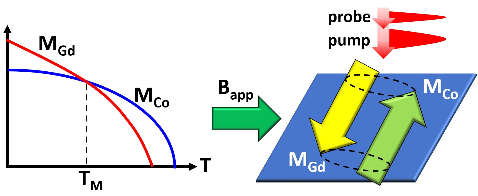
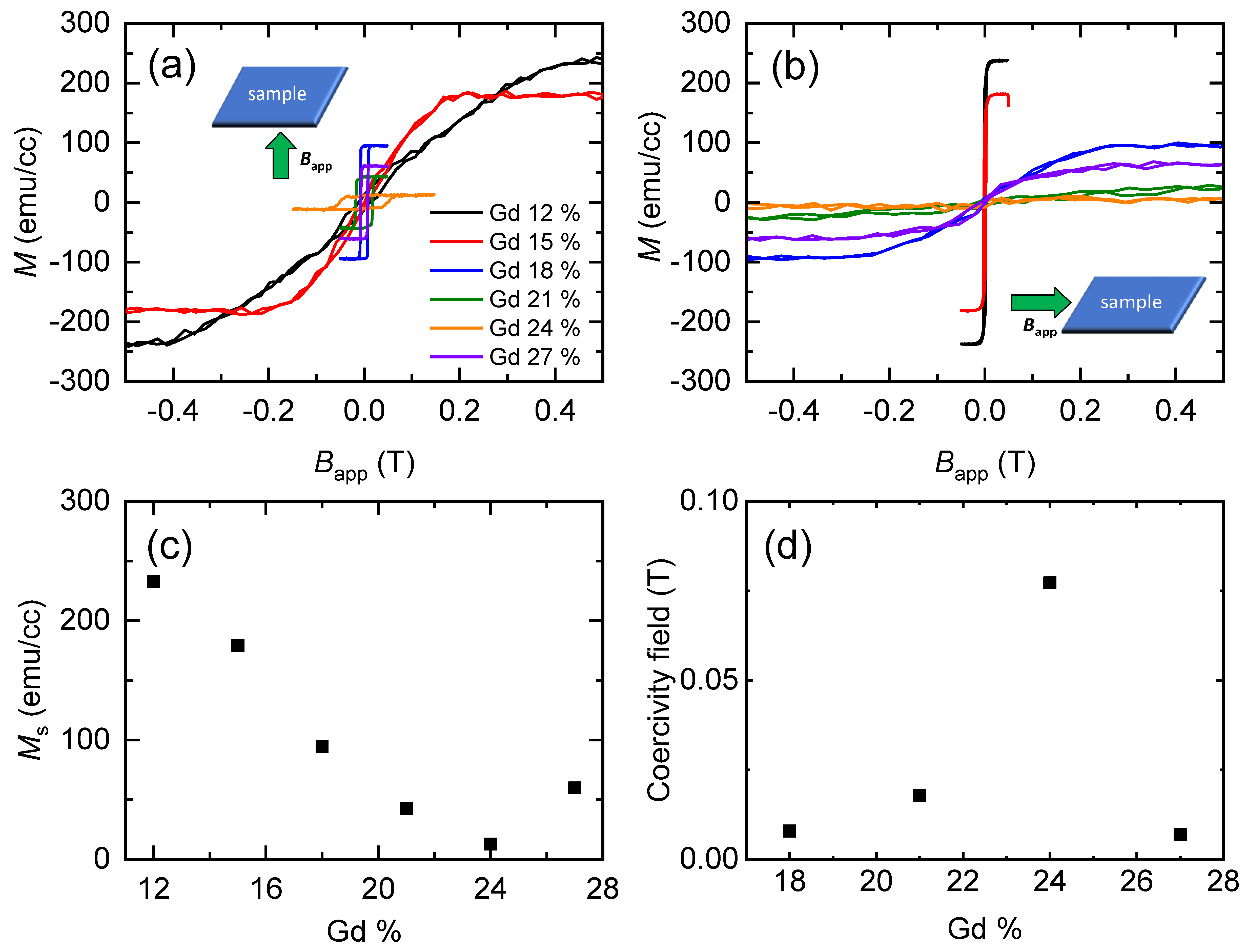
3.1. Basic Magnetic Properties

As basic magnetic properties, we measure the hysteresis of magnetization of the GdCo alloy by applying a magnetic field along the out-of-plane and in-plane directions (Figure 1). At Gd concentrations of 18–27%, the GdCo alloy has a perpendicular magnetic anisotropy, whereas it has an in-plane magnetic anisotropy at Gd concentration of 12–15%. In particular, the net magnetization critically depends on the Gd concentration, and it becomes minimum at a Gd concentration of 24%. Therefore, Gd = 24% is close to the magnetic compensation point. In addition, the coercivity field of the perpendicularly magnetized GdCo alloy reaches a maximum at a Gd concentration of 24%. The coercivity field is often proportional to the perpendicular magnetic anisotropy; accordingly, one may expect the divergence of the magnetic anisotropy at the compensation point. However, a vanishing magnetization compensates for the divergence of the coercivity field. The saturation field along the hard axis can be used for a rough estimation of the magnetic anisotropy energy. Unfortunately, the saturation field is beyond the maximum field of VSM, and the VSM signal becomes too weak with a vanishing net magnetization near the compensation point.

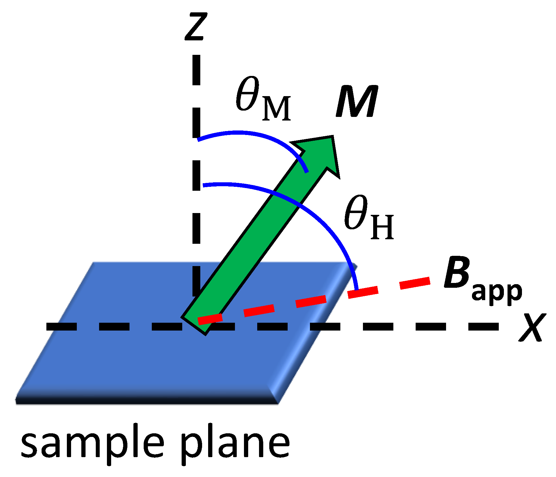
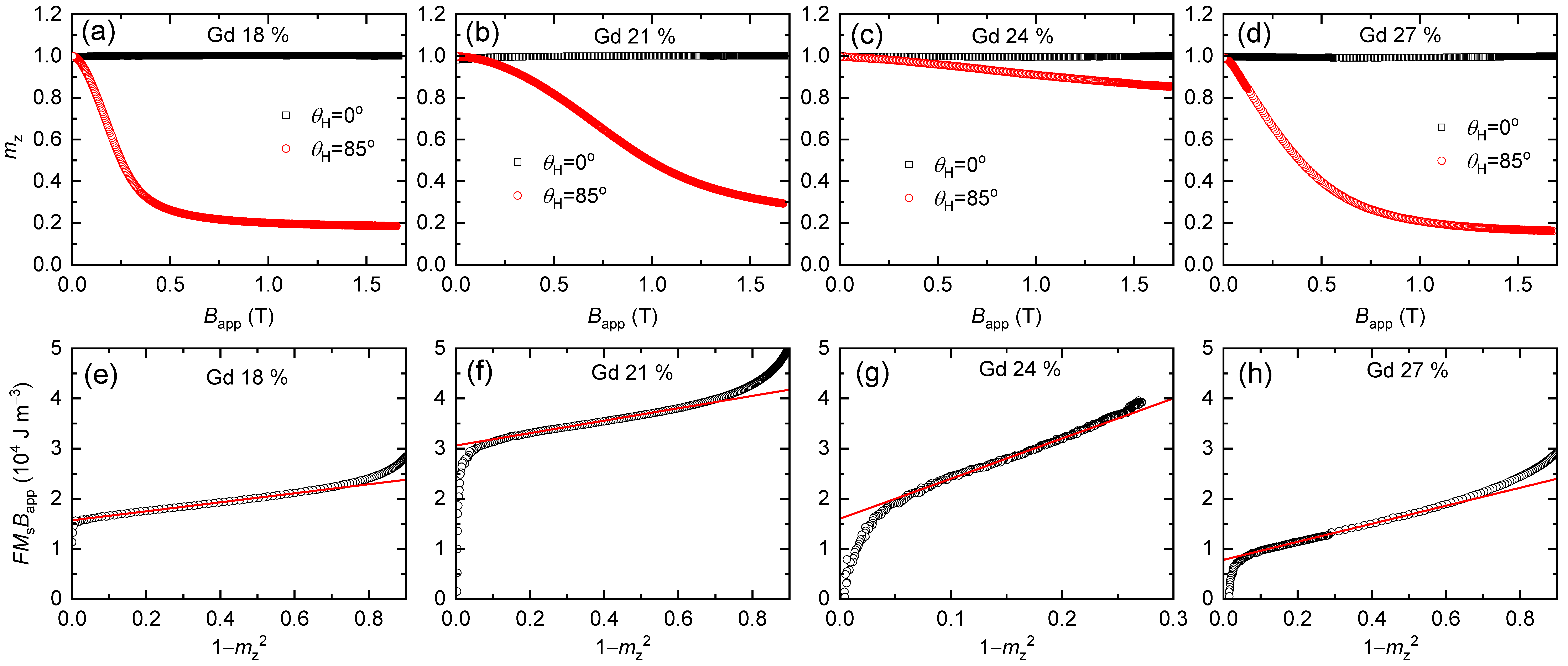
3.2. Determination of Magnetic Anisotropy

To determine the uniaxial magnetic anisotropy of the GdCo alloy, we apply the GST method to the AHE reading of the normalized out-of-plane magnetization, mz = cos θM, where θM is the angle of magnetization from the sample normal (Figure 2). The AHE reading is advantageous over VSM reading in terms of signal-to-noise ratio. As the GST method analyze many mz data with different applied fields (Bapp), it is more accurate than the analysis based on one data point at the saturation field. In addition, as the GST method analyze the gradual change in mz with respect to Bapp, its field requirement is smaller than the saturation field.
We measure mz using AHE with applying Bapp at an oblique angle of θH = 0° or 85° (Figure 2). At θH of 0°, mz is nearly independent of Bapp because AHE signal, which is linearly proportional to M, dominates the ordinal Hall signal, which is linearly proportional to Bapp. With a large θH of 85°, mz gradually decreases with Bapp as the in-plane component of Bapp tilts the magnetization (Figure 3). (θH should be less than 90° to have an out-of-plane component of Bapp, which suppresses multidomain formation.) According to the GST method, the relationship between mz and Bapp can be expressed as [22],
2 ( K 1 μ 0 2 M S 2 ) + 4 K 2 ( 1 m z 2 ) = F B app M S ,
where K1 and K2 are the first and second-order uniaxial anisotropies, MS is the saturation magnetization of the GdCo alloy, and F is given by
F = m sin θ H 1 m z 2 cos θ H m z 1 m z 2 .
Plotting F B app M S vs. 1 m z 2 , K1 and K2 can be determined independently of the intercept and slope, respectively (Figure 3). (For the Gd = 24%, the measured range of the 1 m z 2 is small because the maximum Bapp of 1.7 T is much smaller than the saturation field of B sat 2 K tot M S , where Ktot is the total anisotropy.) The determined values of K1 and K2 with Gd concentrations of 18%, 21%, 24%, and 27% are summarized in Table 1. The maximum Ktot = K1 + K2 of 2.8 × 10⁴ J m−3 is obtained at the compensation point of Gd = 24%. Previously reported values of Ktot of the GdCo alloy are in the range of 104 J m−3, depending on the Gd concentration and deposition method [1,2,20]. We note that the anisotropy energy of the GdCo alloy is about two orders of magnitude smaller than that of FePt, a well-known ferromagnet for strong magnetic anisotropy [22,23]. Such a low magnetic anisotropy of the GdCo alloy limits the application to memory devices. Interestingly, K2 becomes larger than K1 at the compensation point. This observation is surprising because K1 is usually much larger than K2 for typical ferromagnets [22,23]. To understand the physical origin for the strong enhancement of K2 at the compensation point, further theoretical and experimental works are required.

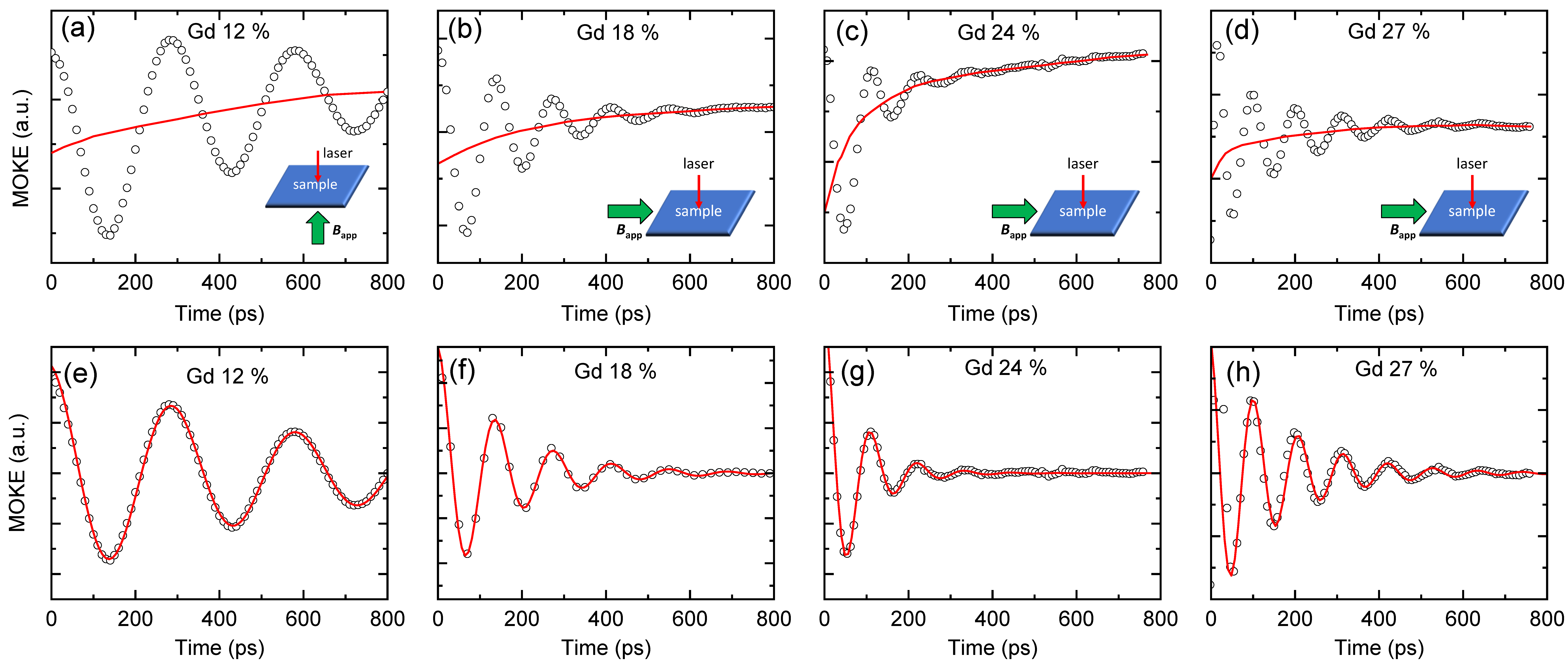
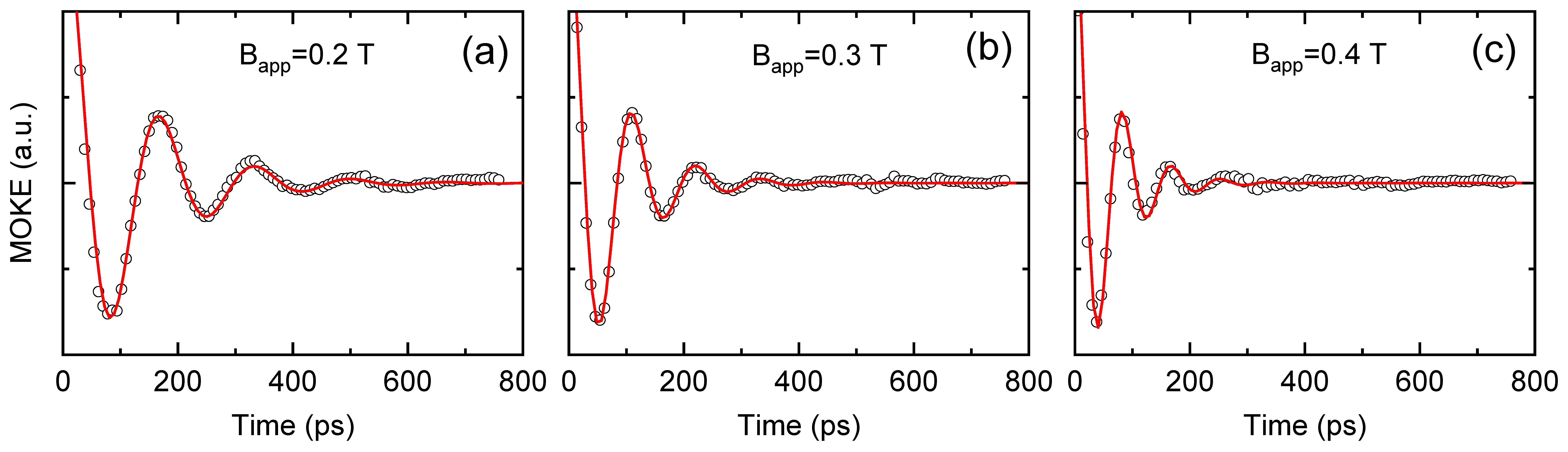
3.3. Determination of Damping Constant

To determine damping constants of the GdCo alloy, we measure the magnetization dynamics using TRMOKE. We use four samples with Gd concentrations of 12%, 18%, 24%, and 27%. The Gd = 12% has in-plane anisotropy, whereas others have out-of-plane anisotropy. To trigger the magnetization precession, we need to apply Bapp along the z/x direction for the in-plane/out-of-plane anisotropy sample. We apply a Bapp of 0.3 T along the x direction for the Gd18Co82, Gd24Co76, and Gd27Co73 samples and Bapp of 0.5 T along the z direction for the Gd12Co88 sample. The magnitude of Bapp is chosen to be larger than the saturation field along the hard axis, so that the initial magnetization aligns along the x or z direction (Figure 1). (This is not the case for the Gd = 24%, in which the saturation field is much larger than Bapp of 0.3 T.) Such an alignment makes the damping analysis to be simple. The equilibrium direction of magnetization is determined by the balance between the uniaxial anisotropy, demagnetization field, and external field. When a pump pulse induces an ultrafast demagnetization via sudden heating, the balance is suddenly disturbed, and a precessional motion of magnetization is triggered [25]. Indeed, the TRMOKE shows a precessional motion on top of an ultrafast demagnetization (Figure 4). We separate the precessional motion by subtracting the demagnetization background signal from the raw data. The precessional motion can be described by the Landau–Lifshitz–Gilbert equation based on the mean-field model [26,27,28,29],
d d t M eff = γ eff M eff × H eff + α eff M eff ( M eff × d d t M eff ) ,
where Meff is the net magnetization of the GdCo alloy, γeff is the effective gyromagnetic ratio of the GdCo alloy, Heff is the effective field combining the exchange field, anisotropy field, demagnetization field, and external field, and αeff is the effective damping of the GdCo alloy. Alternatively, αeff can be obtained as α eff = 1 / ( 2 π f τ ) , where f is the precession frequency, and τ is the relaxation time of the damped cosine function of cos ( 2 π f t ) × exp ( t / τ ) .
We summarize the determined values of Ktot (K1 + K2) and αeff in Figure 5. Both Ktot and αeff maximize at the compensation point of Gd = 24%. Here, αeff is not the intrinsic parameter, but depends on Bapp. For the Gd18Co82 and Gd27Co73 alloys, when magnetization aligns nearly to the x direction by Bapp, the intrinsic damping (αint) is related to αeff as [30],
α int α eff 2 B 1 B 2 B 1 + B 2 ,
where B1 = Bapp + BK, B2 = Bapp, and BK = (2K1μ0MS + 4K2)/MS. For the Gd24Co76 alloy, magnetization aligns nearly to the z direction by strong Bani, then αint≈αeff. The variation of αeff of the Gd24Co76 alloy with different Bapp is shown in Appendix A. Using the BK information in Table 1, we show that αint also maximize at Gd = 24% with a peak value of 0.22. Our result of α = 0.22 is consistent with previous reports of 0.2–0.3 of the GdCo and GdFeCo alloys from the ferromagnetic resonance and TRMOKE measurements [26,27,28]. However, much low α of 0.007 of the GdFeCo alloy was reported from the measurement of the domain wall motion [31]. Further studies are required to resolve this discrepancy between measurement techniques.
Note that the pump pulse induces a significant temperature rise in the sample. Considering Δ T F in A tot / C V d tot , where Fin is the incident fluence of the pump of 12 J m−2, Atot is the absorption coefficient by the total metal layers of ≈ 0.3, CV is the typical heat capacity of metals of 3 × 10⁶ J m−3 K−1, and dtot is the total thickness of metal layers of 21 nm, the temperature rise of the sample would be approximately 60 K (ignoring the slow heat transfer to the substrate). Because the alloy concentration for the magnetic compensation depends on temperature, the Gd24Co76 alloy may not be the magnetic compensation point during TRMOKE. We claim that the increase in αeff is caused by the angular momentum compensation between the Gd and Co sublattices. Such enhancement of αeff near the compensation point has been previously reported for the GdFeCo and GdCo alloys, and the mean-field model was used to explain the physical origin [26,27,28]. According to the mean-field model, αeff of the GdCo alloy is expressed as [29],
α eff = α Co M Co / γ Co + α Gd M Gd / γ Co M Co / γ Co M Gd / γ Co ,
where αCoGd is the damping constant of the Co/Gd sublattice, MCo/MGd is the magnetization of the Co/Gd sublattice, and γCo/γGd is the gyromagnetic ratio of the Co/Gd sublattice. Accordingly, αeff diverges at the compensation of the angular momentum, M / γ . Typically, the angular momentum compensation temperature is 50–100 K higher than the magnetization compensation temperature [13,15,27].

4. Discussion

We investigate the magnetic anisotropy energy and damping constant of the GdCo alloy. By applying the GST method to the AHE measurements, we determine the uniaxial anisotropy energy of 2.8 × 10⁴ J m−3 at the compensation point, Gd concentration of 24%. Surprisingly, we find that the second-order uniaxial anisotropy becomes larger than the first-order one at the compensation point. We expect that this anisotropy inversion is related to the magnetization compensation. Measuring the magnetization dynamics using TRMOKE, we determine the damping constant. An enhanced damping constant of 0.22 is observed at the compensation point. This enhancement is consistent with previous reports and can be understood by the angular momentum compensation.

Author Contributions

Conceptualization, B.-G.P. and G.-M.C.; Sample preparation: J.-G.C. and B.-G.P.; VSM investigation: J.-G.C. and B.-G.P.; AHE investigation, S.J.; TRMOKE investigation: R.S.A. and G.-M.C.; writing—original draft preparation, G.-M.C. All authors have read and agreed to the published version of the manuscript.

Funding

G.-M.C. is funded by the National Research Foundation of Korea (2019R1C1C1009199, 2018M3D1A1058793). B.-G.P. is funded by the National Research Foundation of Korea (2020R1A2C2010309).

Institutional Review Board Statement

Not applicable.

Informed Consent Statement

Not applicable.

Data Availability Statement

Derived data supporting the findings of this study are available from the corresponding author (G.-M.C.) on request.

Conflicts of Interest

The authors declare no conflict of interest.

Appendix A

We measure the magnetization precession of the Gd24Co76 alloy with three different Bapp of 0.2, 0.3, and 0.4 T. From the fittings with a damped cosine function, we determine the same αeff of 0.22 ± 0.02 for all three conditions.
Figure A1. The Bapp dependence on αeff. The precessional motion in the Gd24Co76 alloys with Bapp of (a) 0.2, (b) 0.3, and (c) 0.4 T along the x-direction. The black circles are obtained by subtracting the demagnetization background from the raw data of TRMOKE. The red lines are fittings by damped cosine function of cos ( 2 π f t ) × exp ( t / τ ) . The fitted f values are 6.0, 8.9, and 11.8 GHz for (ac), respectively. The fitted τ values are 120, 80, and 60 ps for (ac), respectively.
Materials 14 02604 g0a1

References

  1. Esho, S.; Fujiwara, S. Growth Induced Anisotropy in Sputtered GdCo Films. In Magnetism and Magnetic Materials, Proceedings of the First Joint MMM-Intermag Conference, Pittsburgh, PA, USA, 15–18 June 1976; AIP Publishing: College Park, MD, USA, 1976; Volume 34, pp. 331–333. [Google Scholar]
  2. Taylor, R.; Gangulee, A. Magnetization and magnetic anisotropy in evaporated GdCo amorphous films. J. Appl. Phys. 1976, 47, 4666–4668. [Google Scholar] [CrossRef]
  3. Mizoguchi, T.; Cargill, G., III. Magnetic anisotropy from dipolar interactions in amorphous ferrimagnetic alloys. J. Appl. Phys. 1979, 50, 3570–3582. [Google Scholar] [CrossRef]
  4. Ostler, T.A.; Evans, R.F.L.; Chantrell, R.W.; Atxitia, U.; Chubykalo-Fesenko, O.; Radu, I.; Abrudan, R.; Radu, F.; Tsukamoto, A.; Itoh, A.; et al. Crystallographically amorphous ferrimagnetic alloys: Comparing a localized atomistic spin model with experiments. Phys. Rev. B 2011, 84, 024407. [Google Scholar] [CrossRef] [Green Version]
  5. Stanciu, C.D.; Hansteen, F.; Kimel, A.V.; Kirilyuk, A.; Tsukamoto, A.; Itoh, A.; Rasing, T. All-optical magnetic recording with circularly polarized light. Phys. Rev. Lett. 2007, 99, 047601. [Google Scholar] [CrossRef] [Green Version]
  6. Kirilyuk, A.; Kimel, A.V.; Rasing, T. Laser-induced magnetization dynamics and reversal in ferrimagnetic alloys. Rep. Prog. Phys. 2013, 76, 026501. [Google Scholar] [CrossRef] [PubMed]
  7. Hansen, P.; Clausen, C.; Much, G.; Rosenkranz, M.; Witter, K. Magnetic and magneto-optical properties of rare-earth transition-metal alloys containing Gd, Tb, Fe, Co. J. Appl. Phys. 1989, 66, 756–767. [Google Scholar] [CrossRef]
  8. Jiang, X.; Gao, L.; Sun, J.Z.; Parkin, S.S.P. Temperature dependence of current-induced magnetization switching in spin valves with a ferrimagnetic CoGd free layer. Phys. Rev. Lett. 2006, 97, 217202. [Google Scholar] [CrossRef] [Green Version]
  9. Yang, Y.; Wilson, R.B.; Gorchon, J.; Lambert, C.-H.; Salahuddin, S.; Bokor, J. Ultrafast magnetization reversal by picosecond electrical pulses. Sci. Adv. 2017, 3, e1603117. [Google Scholar] [CrossRef] [Green Version]
  10. Mishra, R.; Yu, J.; Qiu, X.; Motapothula, M.; Venkatesan, T.; Yang, H. Anomalous current-induced spin torques in ferrimagnets near compensation. Phys. Rev. Lett. 2017, 118, 167201. [Google Scholar] [CrossRef] [Green Version]
  11. Cai, K.; Zhu, Z.; Lee, J.M.; Mishra, R.; Ren, L.; Pollard, S.D.; He, P.; Liang, G.; Teo, K.L.; Yang, H. Ultrafast and energy-efficient spin–orbit torque switching in compensated ferrimagnets. Nat. Electron. 2020, 3, 37–42. [Google Scholar] [CrossRef]
  12. Sala, G.; Krizakova, V.; Grimaldi, E.; Lambert, C.-H.; Devolder, T.; Gambardella, P. Real-time Hall-effect detection of current-induced magnetization dynamics in ferrimagnets. Nat. Commun. 2021, 12, 1–9. [Google Scholar] [CrossRef] [PubMed]
  13. Kim, K.-J.; Kim, S.K.; Hirata, Y.; Oh, S.-H.; Tono, T.; Kim, D.-H.; Okuno, T.; Ham, W.S.; Kim, S.; Go, G.; et al. Fast domain wall motion in the vicinity of the angular momentum compensation temperature of ferrimagnets. Nat. Mater. 2017, 16, 1187–1192. [Google Scholar] [CrossRef] [PubMed] [Green Version]
  14. Siddiqui, S.A.; Han, J.; Finley, J.T.; Ross, C.A.; Liu, L. Current-induced domain wall motion in a compensated ferrimagnet. Phys. Rev. Lett. 2018, 121, 057701. [Google Scholar] [CrossRef] [PubMed] [Green Version]
  15. Caretta, L.; Mann, M.; Büttner, F.; Ueda, K.; Pfau, B.; Günther, C.M.; Hessing, P.; Churikova, A.; Klose, C.; Schneider, M.; et al. Fast current-driven domain walls and small skyrmions in a compensated ferrimagnet. Nat. Nanotechnol. 2018, 13, 1154–1160. [Google Scholar] [CrossRef] [PubMed]
  16. Ikeda, S.; Miura, K.T.; Yamamoto, H.; Mizunuma, K.; Gan, H.D.; Endo, M.; Kanai, S.; Hayakawa, J.; Matsukura, F.; Ohno, H. A perpendicular-anisotropy CoFeB–MgO magnetic tunnel junction. Nat. Mater. 2010, 9, 721–724. [Google Scholar] [CrossRef]
  17. Ohmori, H.; Hatori, T.; Nakagawa, S. Perpendicular magnetic tunnel junction with tunneling magnetoresistance ratio of 64% using MgO (100) barrier layer prepared at room temperature. J. Appl. Phys. 2008, 103, 07A911. [Google Scholar] [CrossRef]
  18. Yoshikawa, M. Tunnel magnetoresistance over 100% in MgO-based magnetic tunnel junction films with perpendicular magnetic L10-FePt electrodes. IEEE Trans. Magn. 2008, 44, 2573–2576. [Google Scholar] [CrossRef]
  19. Rahman, M.T.; Liu, X.; Morisako, A. TiN underlayer and overlayer for TbFeCo perpendicular magnetic recording media. J. Magn. Magn. Mater. 2006, 303, e133–e136. [Google Scholar] [CrossRef]
  20. Ceballos, A.; Pattabi, A.; El-Ghazaly, A.; Ruta, S.; Simon, C.P.; Evans, R.F.L.; Ostler, T.; Chantrell, R.W.; Kennedy, E.; Scott, M.; et al. Role of element-specific damping in ultrafast, helicity-independent, all-optical switching dynamics in amorphous (Gd,Tb)Co thin films. Phys. Rev. B 2021, 103, 024438. [Google Scholar] [CrossRef]
  21. Sucksmith, W.; Thompson, J.E. The magnetic anisotropy of cobalt. R. Soc. Lond. Ser. A Math. Phys. Sci. 1954, 225, 362–375. [Google Scholar]
  22. Okamoto, S.; Kikuchi, N.; Kitakami, O.; Miyazaki, T.; Shimada, Y.; Fukamichi, K. Chemical-order-dependent magnetic anisotropy and exchange stiffness constant of FePt (001) epitaxial films. Phys. Rev. B 2002, 66, 024413. [Google Scholar] [CrossRef]
  23. Choi, G.-M.; Min, B.-C.; Shin, K.-H. L10 Ordering of FePtB Films on a Thin MgO Layer. Appl. Phys. Express 2011, 4, 023001. [Google Scholar] [CrossRef]
  24. Nagaosa, N.; Sinova, J.; Onoda, S.; Macdonald, A.H.; Ong, N.P. Anomalous hall effect. Rev. Mod. Phys. 2010, 82, 1539–1592. [Google Scholar] [CrossRef] [Green Version]
  25. Van Kampen, M.M.; Jozsa, C.C.; Kohlhepp, J.J.; LeClair, P.P.; Lagae, L.L.; De Jonge, W.J.M.; Koopmans, B.B. All-optical probe of coherent spin waves. Phys. Rev. Lett. 2002, 88, 227201. [Google Scholar] [CrossRef] [PubMed] [Green Version]
  26. Binder, M.; Weber, A.; Mosendz, O.; Woltersdorf, G.; Izquierdo, M.; Neudecker, I.; Dahn, J.R.; Hatchard, T.D.; Thiele, J.-U.; Back, C.H.; et al. Magnetization dynamics of the ferrimagnet CoGd near the compensation of magnetization and angular momentum. Phys. Rev. B 2006, 74, 134404. [Google Scholar] [CrossRef] [Green Version]
  27. Stanciu, C.D.; Kimel, A.V.; Hansteen, F.; Tsukamoto, A.; Itoh, A.; Kirilyuk, A.; Rasing, T. Ultrafast spin dynamics across compensation points in ferrimagnetic GdFeCo: The role of angular momentum compensation. Phys. Rev. B. 2006, 73, 220402. [Google Scholar] [CrossRef] [Green Version]
  28. Kato, T.; Nakazawa, K.; Komiya, R.; Nishizawa, N.; Tsunashima, S.; Iwata, S. Compositional dependence of g-factor and damping constant of GdFeCo amorphous alloy films. IEEE Trans. Magn. 2008, 44, 3380–3383. [Google Scholar] [CrossRef]
  29. Wangsness, R.K. Sublattice effects in magnetic resonance. Phys. Rev. 1953, 91, 1085–1091. [Google Scholar] [CrossRef]
  30. Mizukami, S. Fast magnetization precession obsereved in L10-FePt epitaxial thin film. Appl. Phys. Lett. 2011, 98, 052501. [Google Scholar] [CrossRef]
  31. Kim, D.-H.; Okuno, T.; Kim, S.K.; Oh, S.-H.; Nishimura, T.; Hirata, Y.; Futakawa, Y.; Yoshikawa, H.; Tsukamoto, A.; Tserkovnyak, Y.; et al. Low magnetic damping of ferrimagnetic GdFeCo alloys. Phys. Rev. Lett. 2019, 122, 127203. [Google Scholar] [CrossRef] [Green Version]
Figure 1. VSM results. Magnetization hysteresis of the GdxCo1-x alloy, x from 12% to 27%, applying the magnetic field (a) out-of-plane and (b) in-plane directions. (c) The saturation magnetization of the GdxCo1-x alloy. (d) The coercivity field of the out-of-plane anisotropy GdxCo1-x alloy.
Materials 14 02604 g001
Figure 2. Angle definition for AHE measurements. The normal to the sample plane is defined as the z axis. When a magnetic field (Bapp) is applied at the angle of θH with respect to the z axis, the magnetization (M) tilts at an angle of θM, which is determined by the balance between the uniaxial anisotropy energy and Zeeman energy.
Materials 14 02604 g002
Figure 3. AHE results. The normalized AHE voltage (mz) of the (a) Gd18Co82, (b) Gd21Co79, (c) Gd24Co76, and (d) Gd27Co73 alloys. The magnetic field is applied with an oblique angle, θH, with respect to the film normal direction. The black/red color corresponds to the θH of 0°/85°. The GST analysis of the (e) Gd18Co82, (f) Gd21Co79, (g) Gd24Co76, and (h) Gd27Co73 alloys. The black squares are the data obtained from (ad) with θH of 85°. The red lines are fittings with Equation (1). The fitted values of the uniaxial anisotropy are summarized in Table 1.
Materials 14 02604 g003
Figure 4. TRMOKE results. The magnetization dynamics triggered by a pump pulse in the (a) Gd12Co88, (b) Gd18Co72, (c) Gd24Co76, and (d) Gd27Co73 alloys. A magnetic field of 0.5 T/0.3 T is applied along the z/x direction for (a)/(bd). The black circles are the measure data. The red lines are the background demagnetization signal. The extracted precessional motion in the (e) Gd12Co88, (f) Gd18Co72, (g) Gd24Co76, and (h) Gd27Co73 alloys. The black circles are obtained by subtracting the demagnetization background from the raw data of (ad). The red lines are fittings by damped cosine function of cos ( 2 π f t ) × exp ( t / τ ) . The fitted f values are 3.4, 7.2, 8.9, and 9.4 GHz for (eh), respectively. The fitted τ values are 600, 160, 80, and 160 ps for (eh), respectively.
Materials 14 02604 g004
Figure 5. Summary of the uniaxial anisotropy (K) and damping constant (α). (a) The K values of the GdCo alloy. The black square/red circle/blue triangle corresponds to the first order (K1)/second order (K2)/total (K1 + K2) anisotropy. The error range in the K1 and K2 determination is 20% considering the 10% uncertainty in MS of VSM measurements and ±1° error in θH of AHE measurements. (b) The α values of the GdCo alloy. The black square/red circle corresponds to the effective damping (αeff)/intrinsic damping (αint). The αeff is obtained from the fitting of the precession motion. The αint is obtained using Equation (4) for the Gd = 12%, 18%, and 27%. For the Gd = 24%, we assume αint is the same as αeff. The error range in the αeff determination is 10% considering the fitting uncertainties of f and τ.
Materials 14 02604 g005
Table 1. The first-order (K1) and second-order (K2) uniaxial anisotropy of the GdCo alloy, with the Gd concentration of 18%, 21%, 24%, and 27%. The K1eff and K2 values are determined from the linear fitting of Figure 2e–h. The K1 values are obtained from K1eff by K1 = K1eff + μ0M2/2.
Colume HeadingGd18Co82Gd21Co79Gd24Co76Gd27Co73
K1eff (J m−3)7.9 × 10315.3 × 1038 × 1033.9 × 103
μ0M2/2 (J m−3)5.6 × 1031.1 × 1030.1 × 1032.3 × 103
K1 (J m−3)13.5 × 10316.4 × 1038.1 × 1036.2 × 103
K2 (J m−3)2.3 × 1033.1 × 10320 × 1034.5 × 103
K1 + K2 (J m−3)15.8 × 10319.5 × 10328.1 × 10310.7 × 103
Publisher’s Note: MDPI stays neutral with regard to jurisdictional claims in published maps and institutional affiliations.

