Embrittlement Due to Excess Heat Input into Friction Stir Processed 7075 Alloy


Abstract
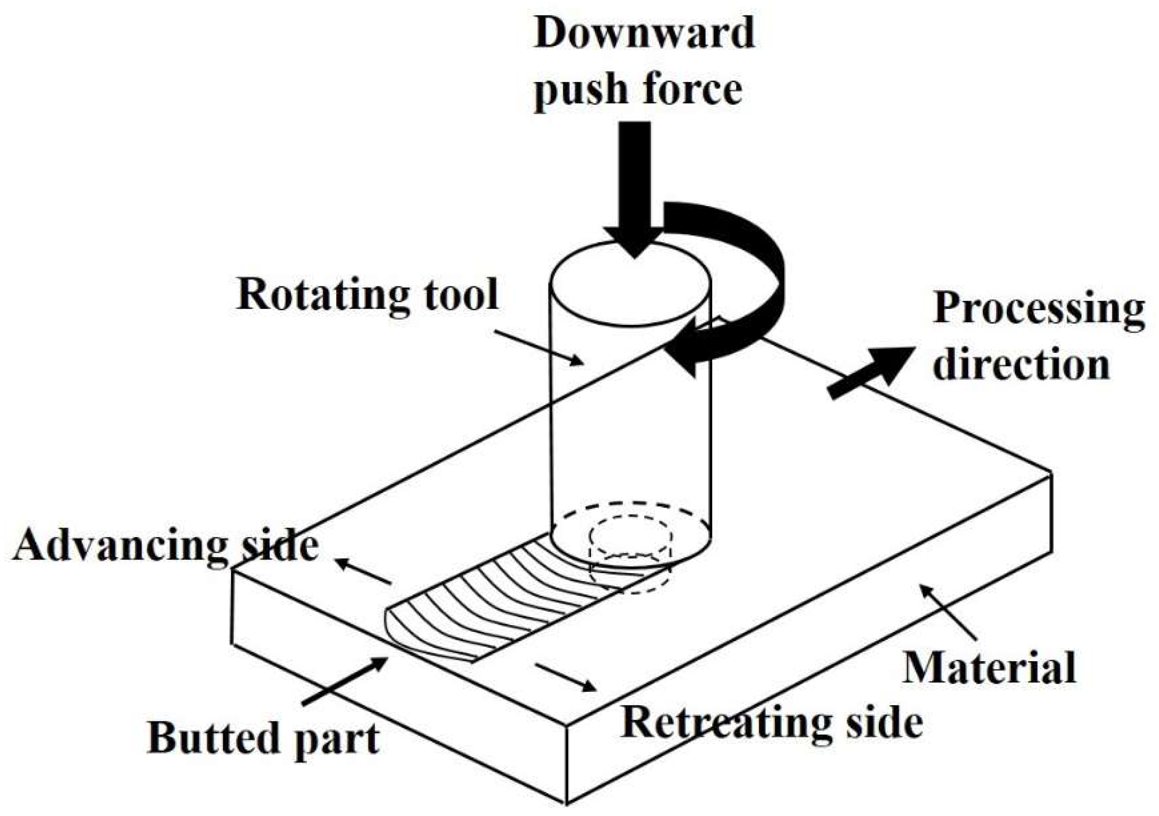
1. Introduction
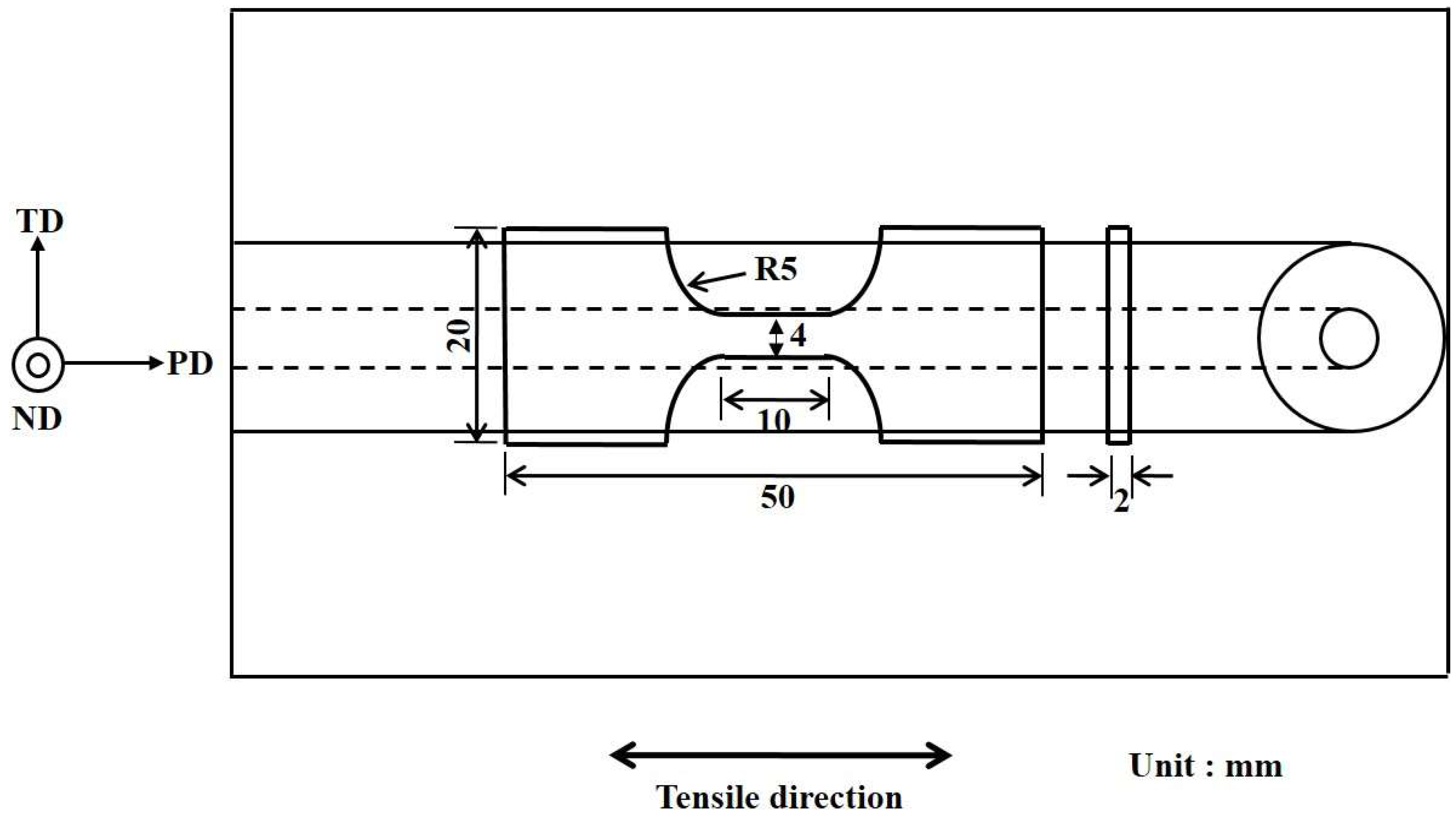
2. Materials and Methods
3. Results and Discussion
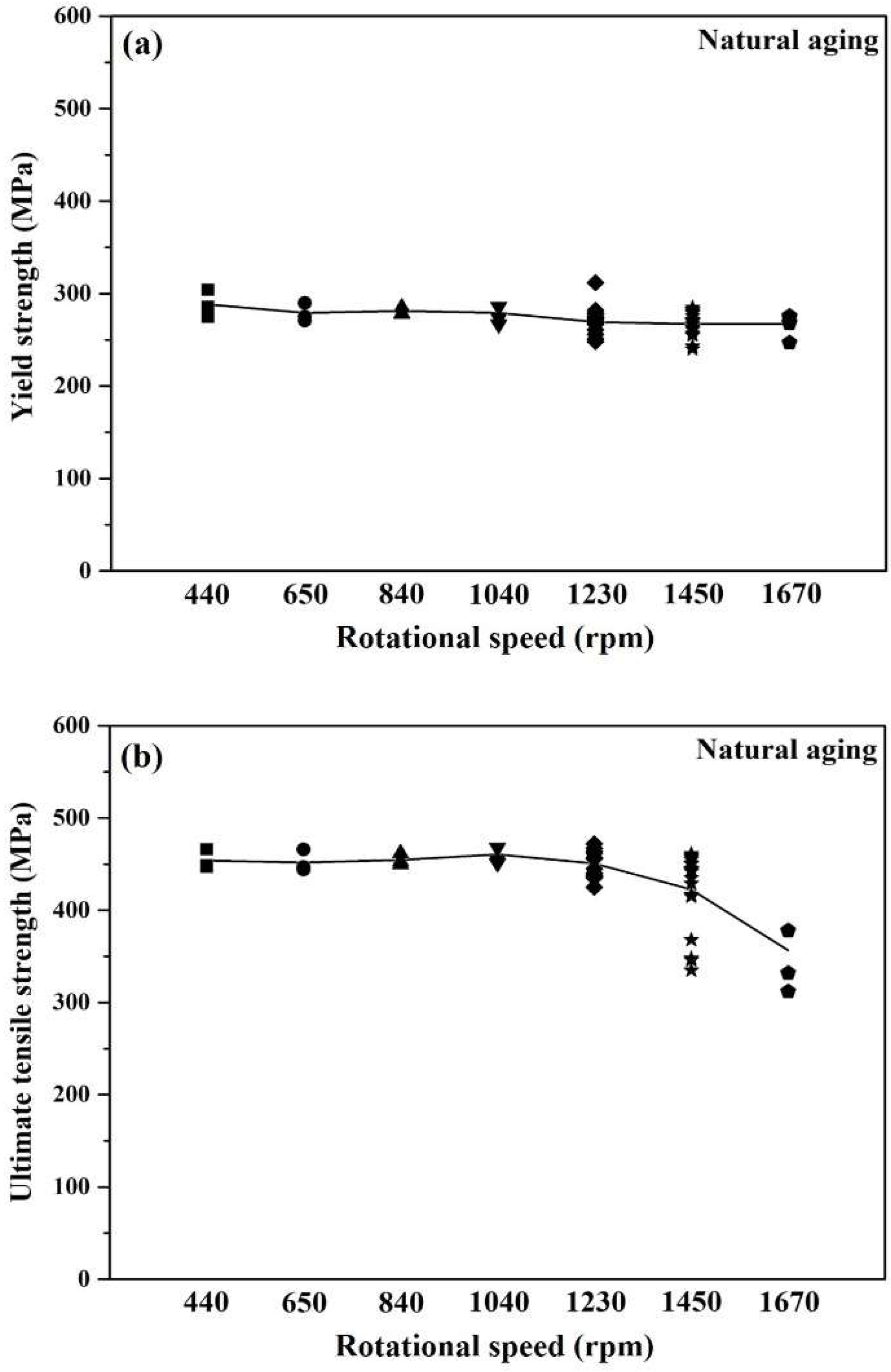
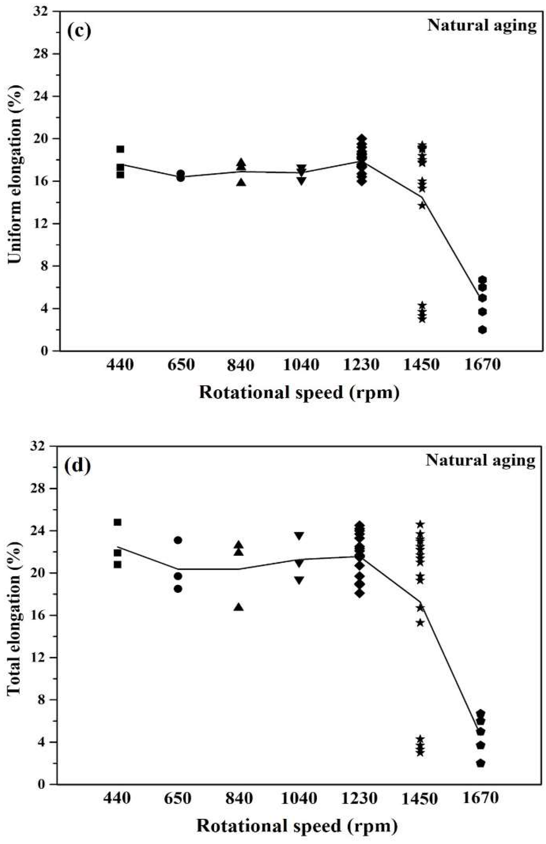
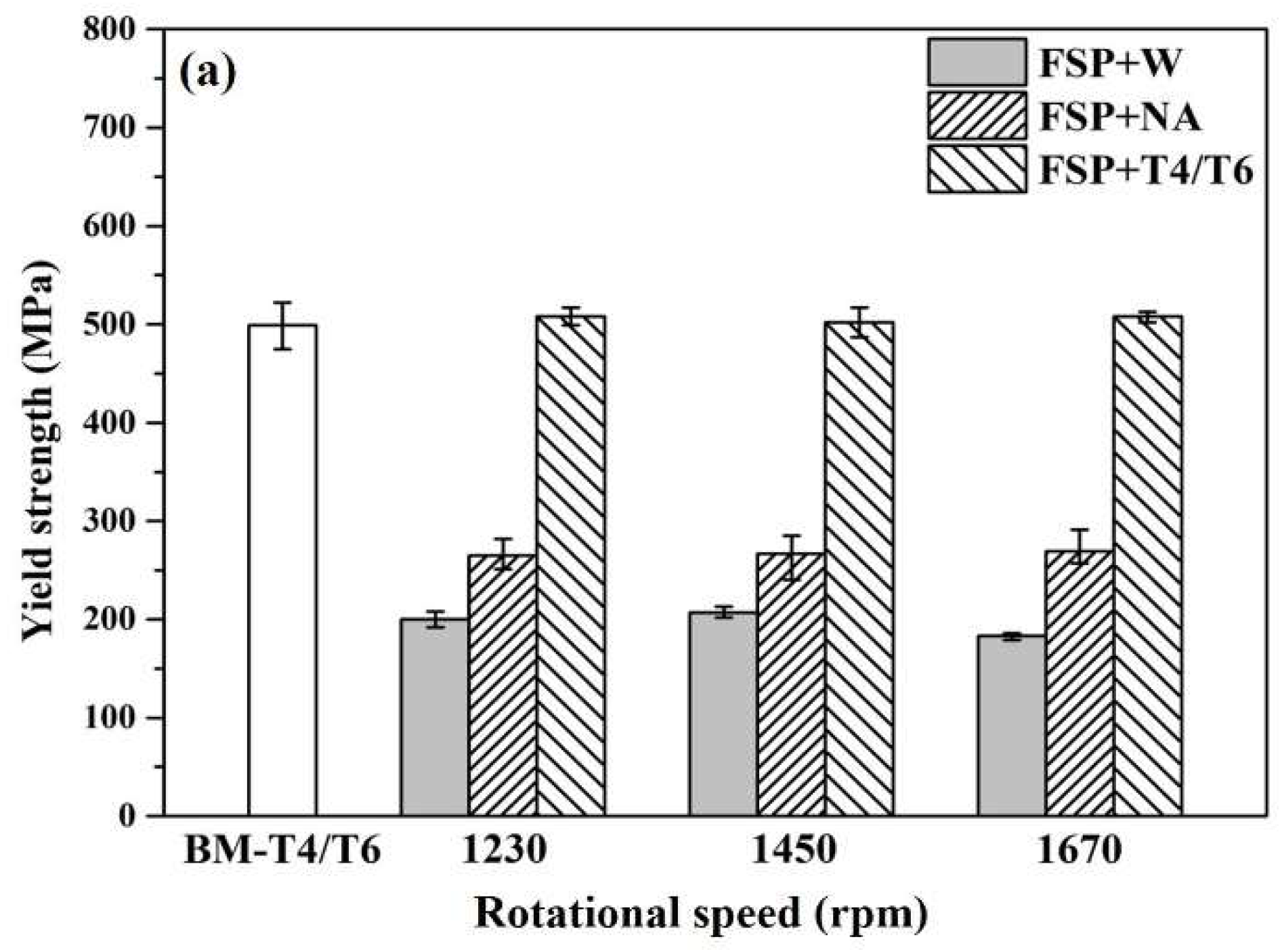
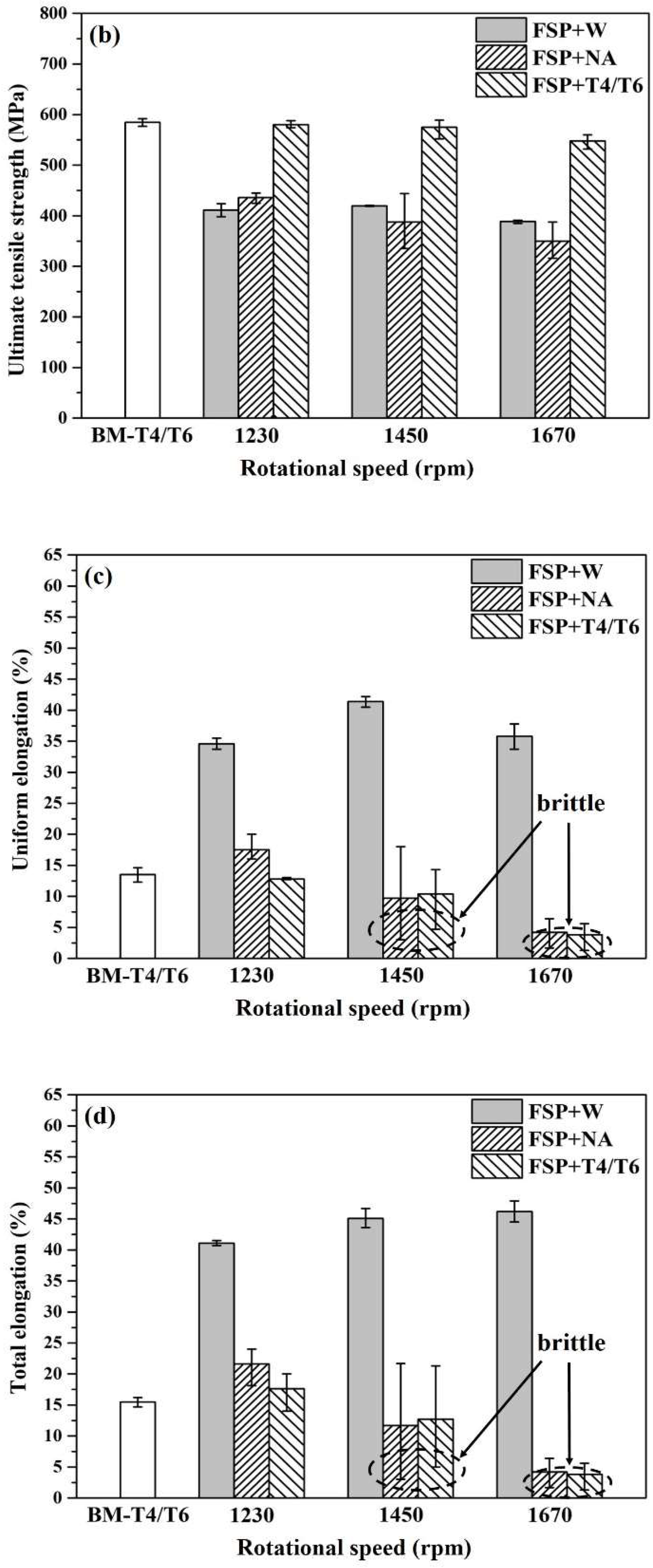
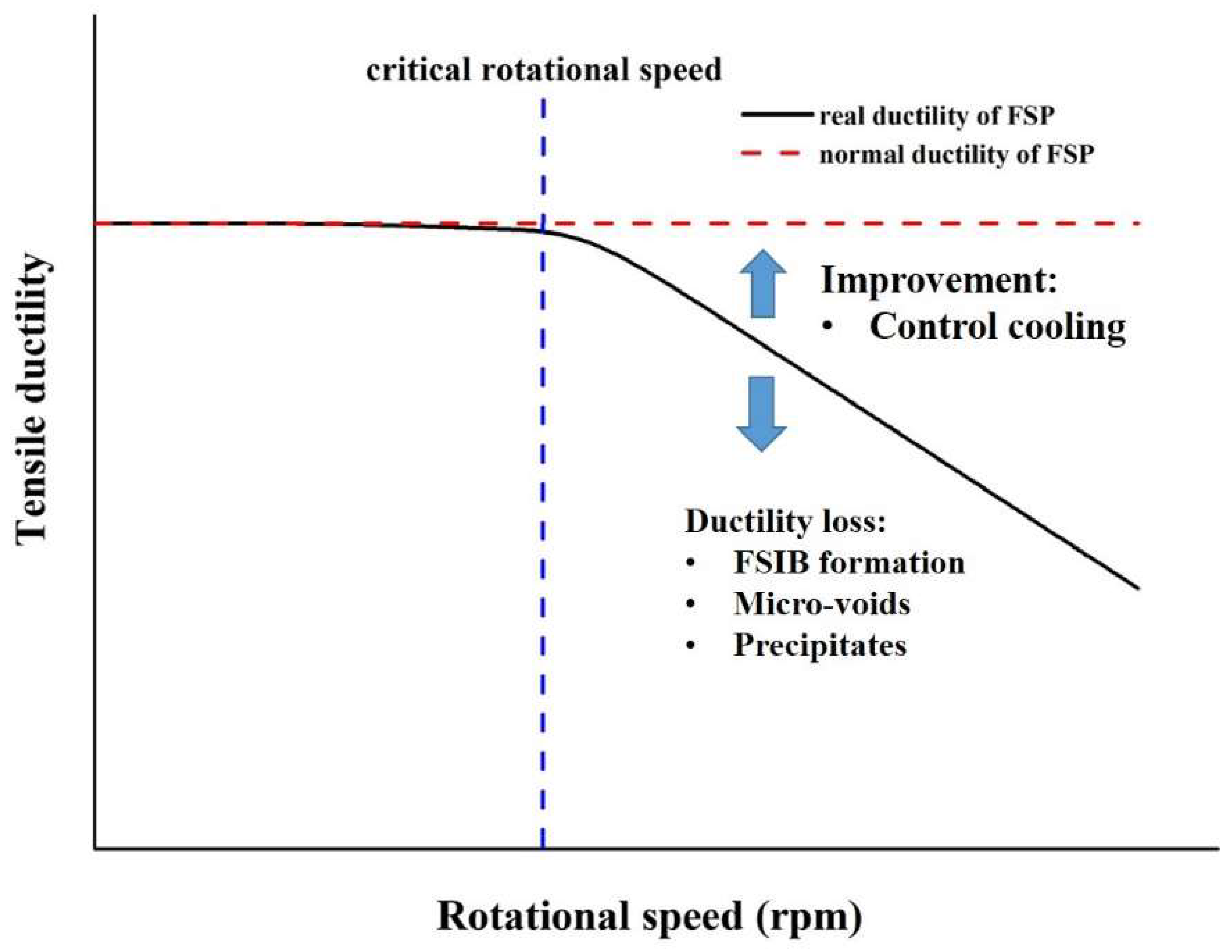
3.1. Critical Condition of Ductile-to-Brittle Transition (DBT) Due to Excess Heat-Input
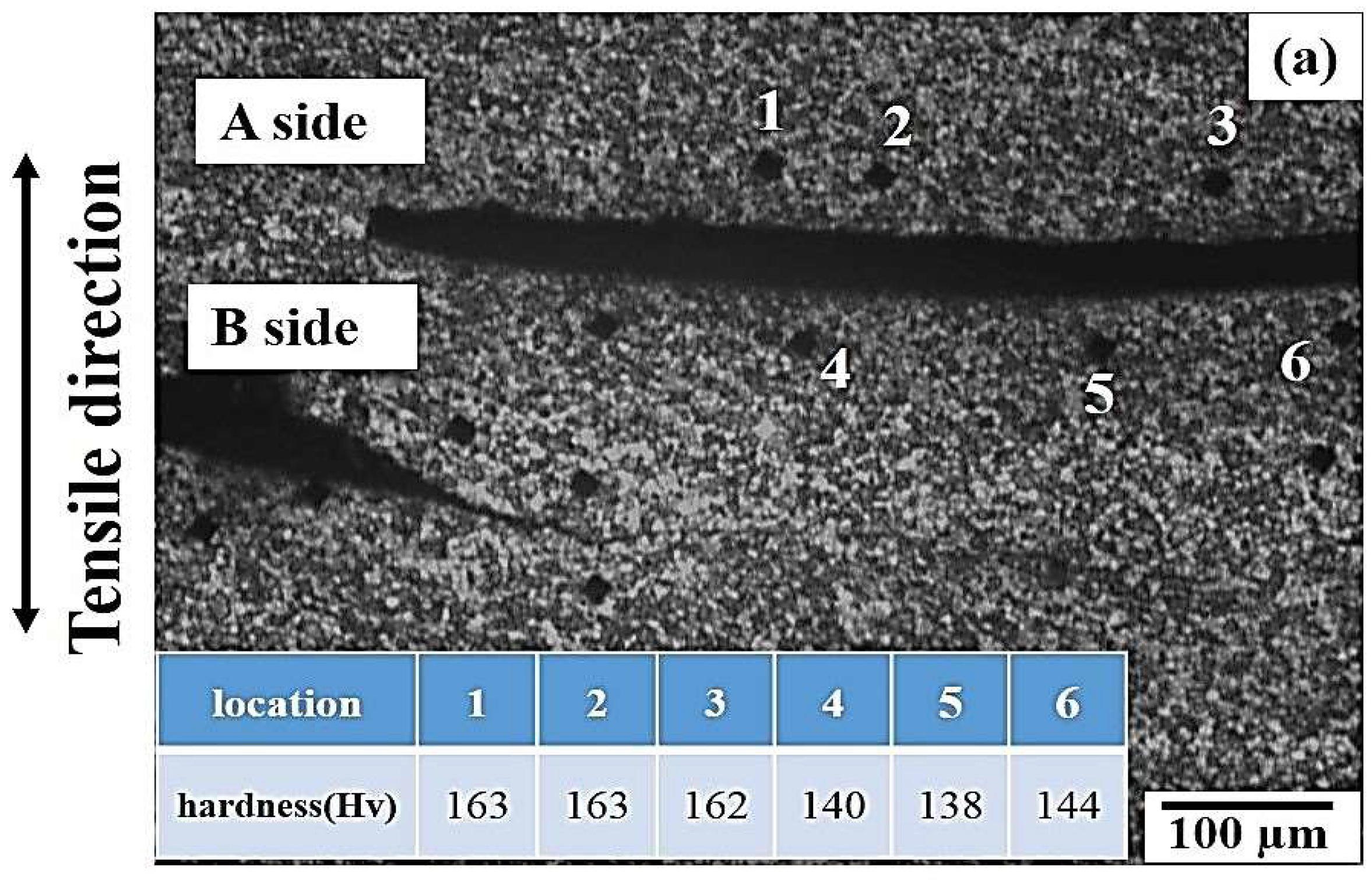
3.2. Emergence of FSIB and Micro-Voids on the Susceptibility of DBT
4. Conclusions
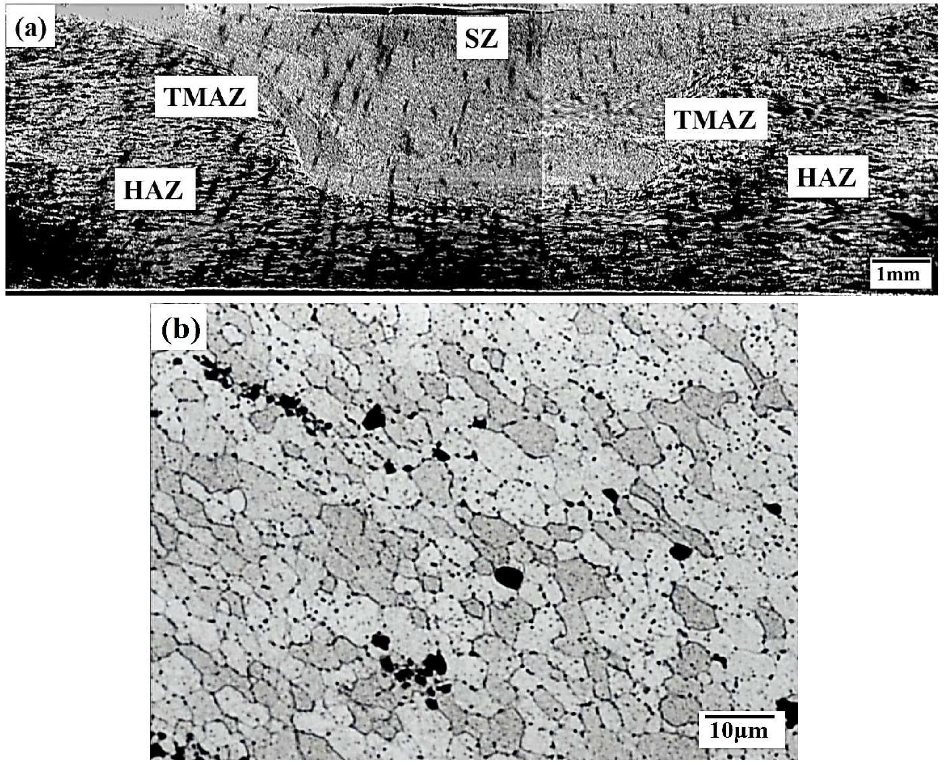
- We observed that the average grain size did not change with an increase of the rotational speed to 1670 rpm and after through solutionizing temperature at 753 K.
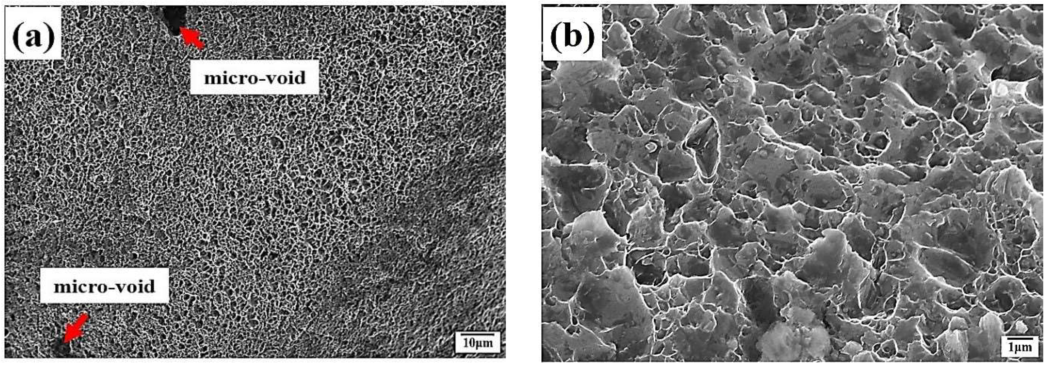
- The dependence of the ductile-to-brittle transition (DBT) phenomenon on rotational speed was confirmed. An increase in the rotation speed to 1450 rpm resulted in the brittle fracture pattern being found in a large proportion of the sample while the obtained tensile ductility showed large data fluctuation.
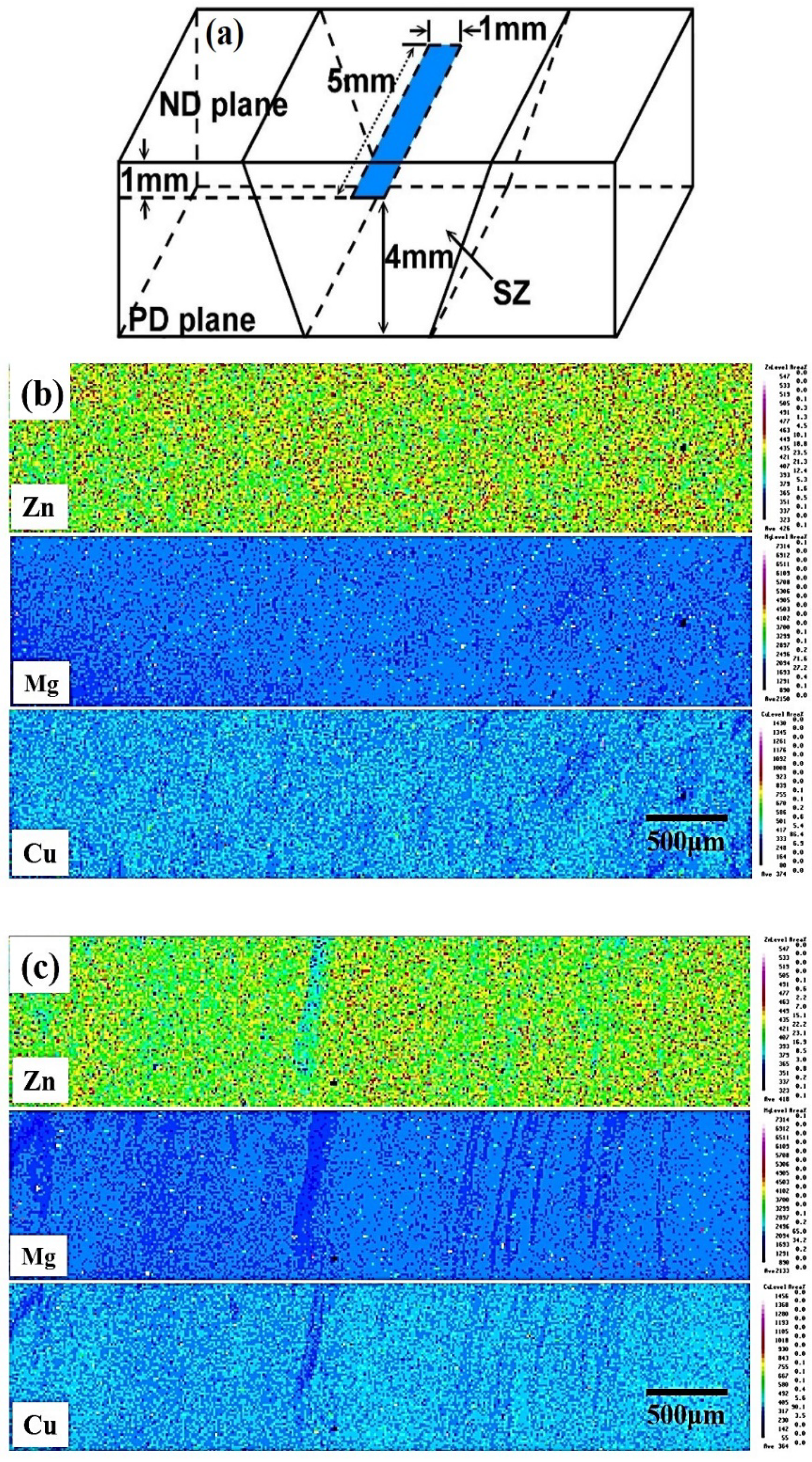
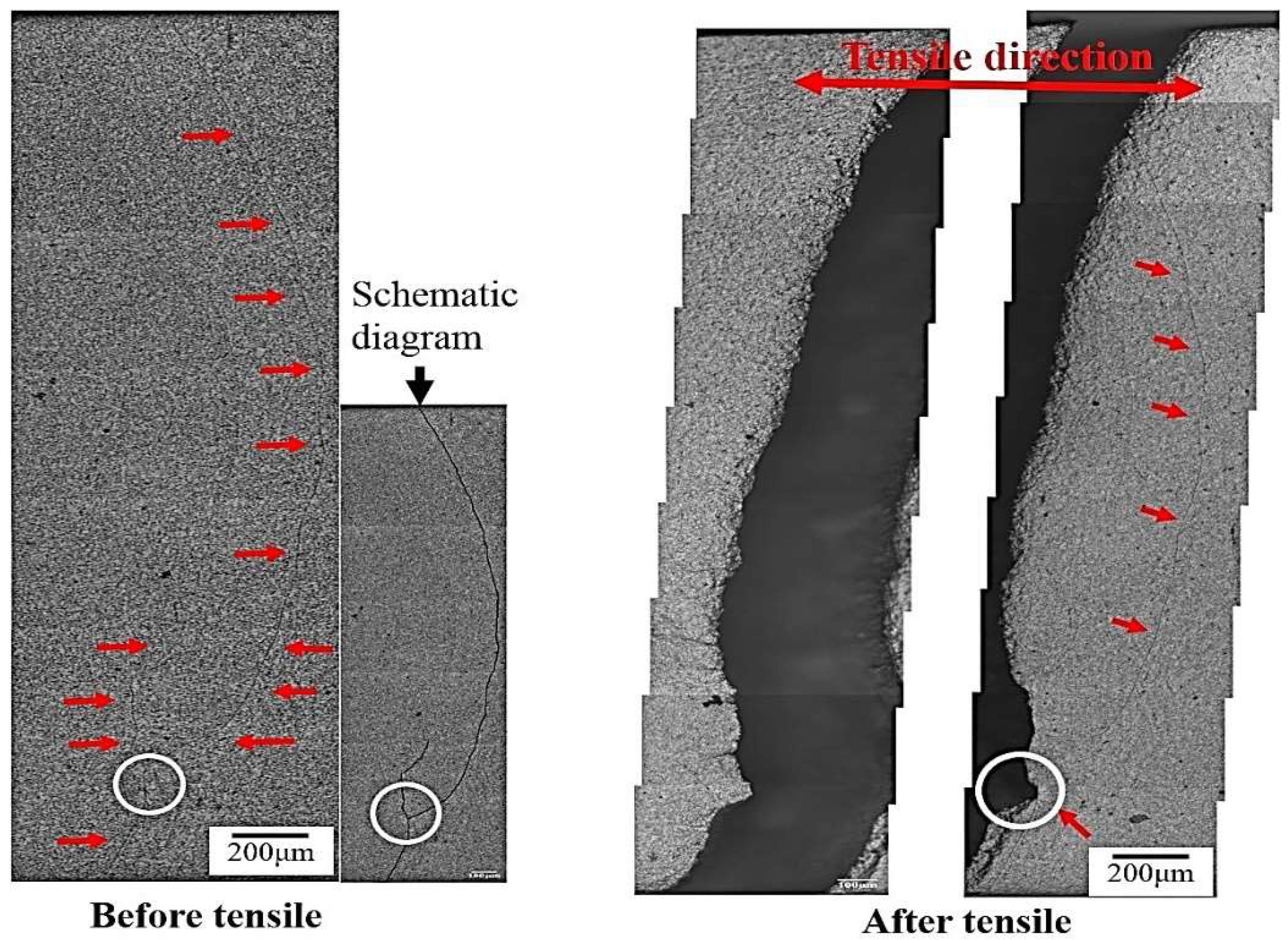
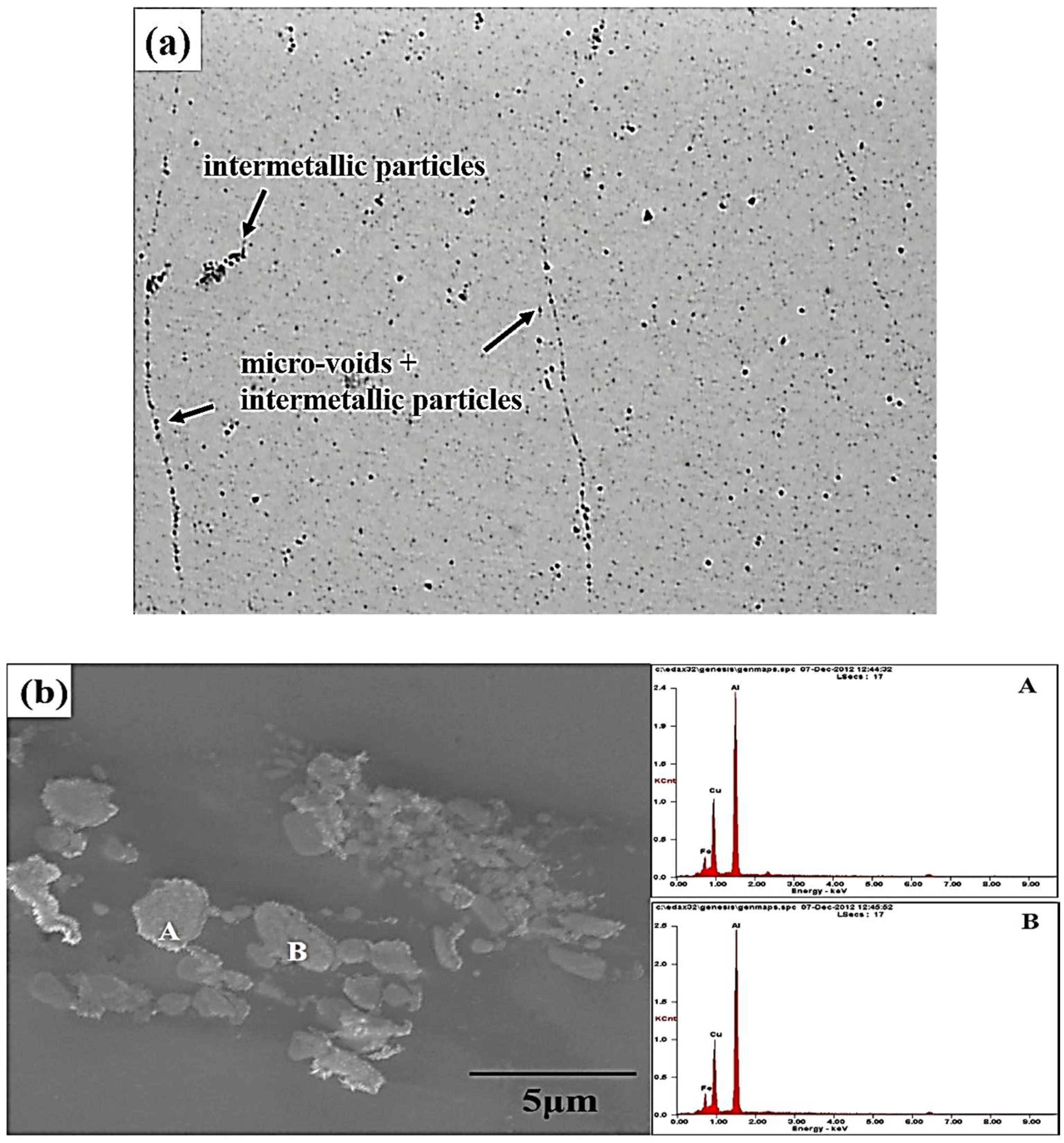
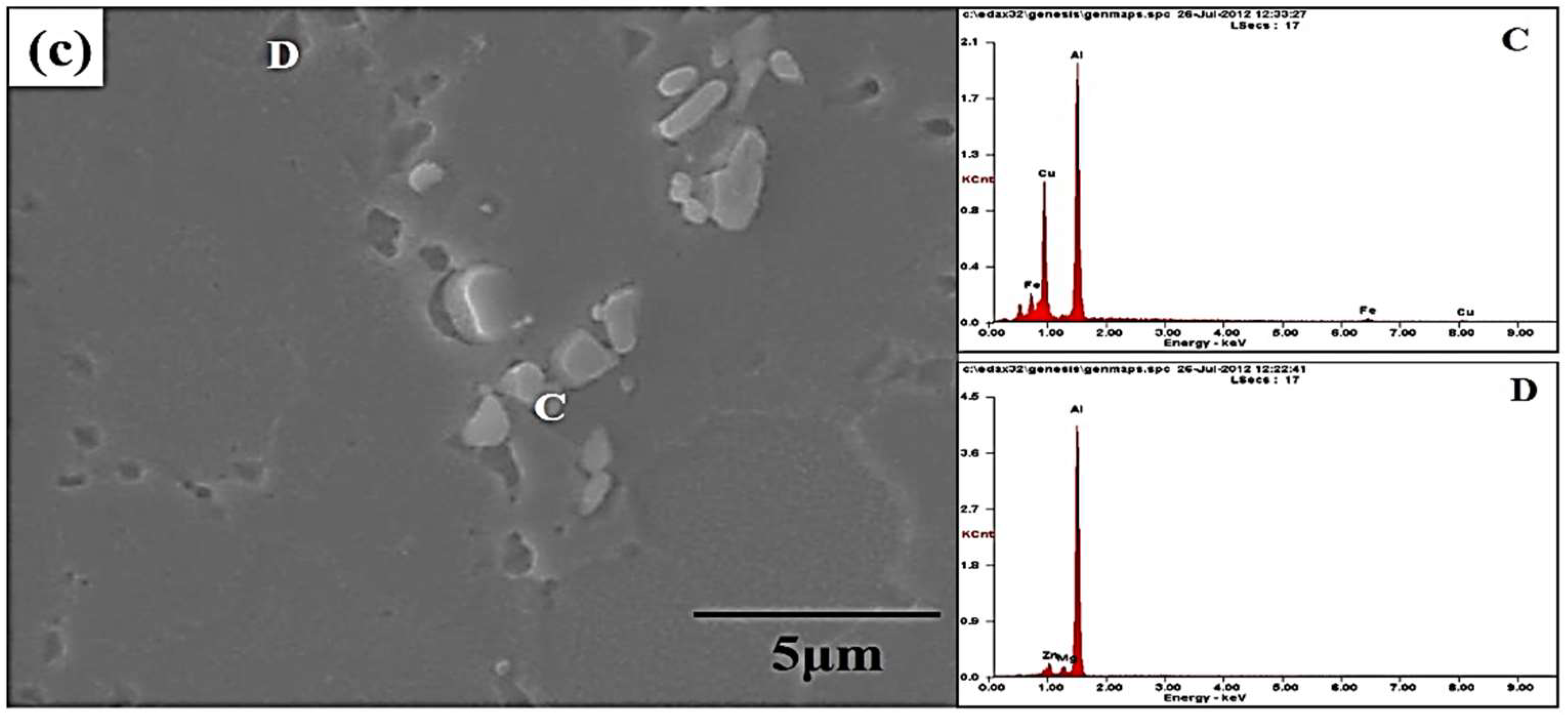
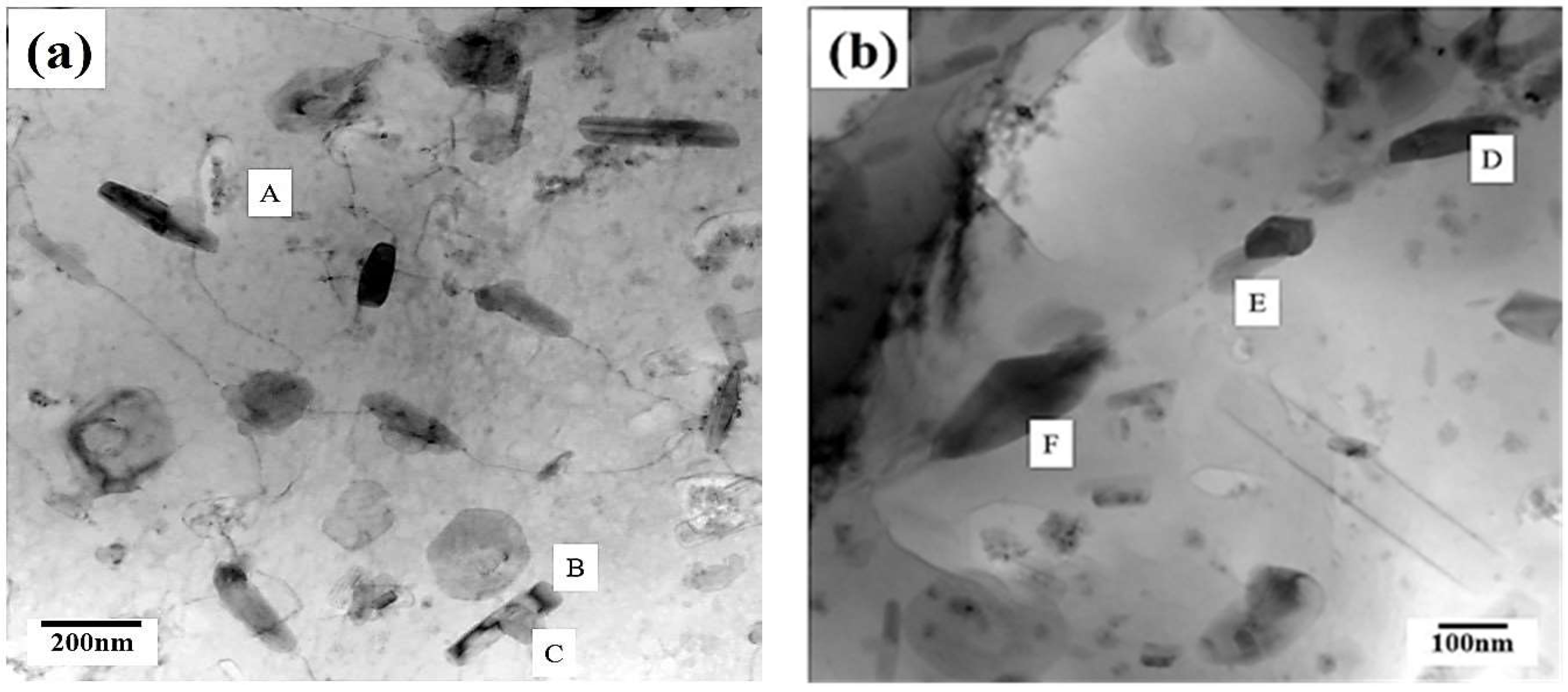
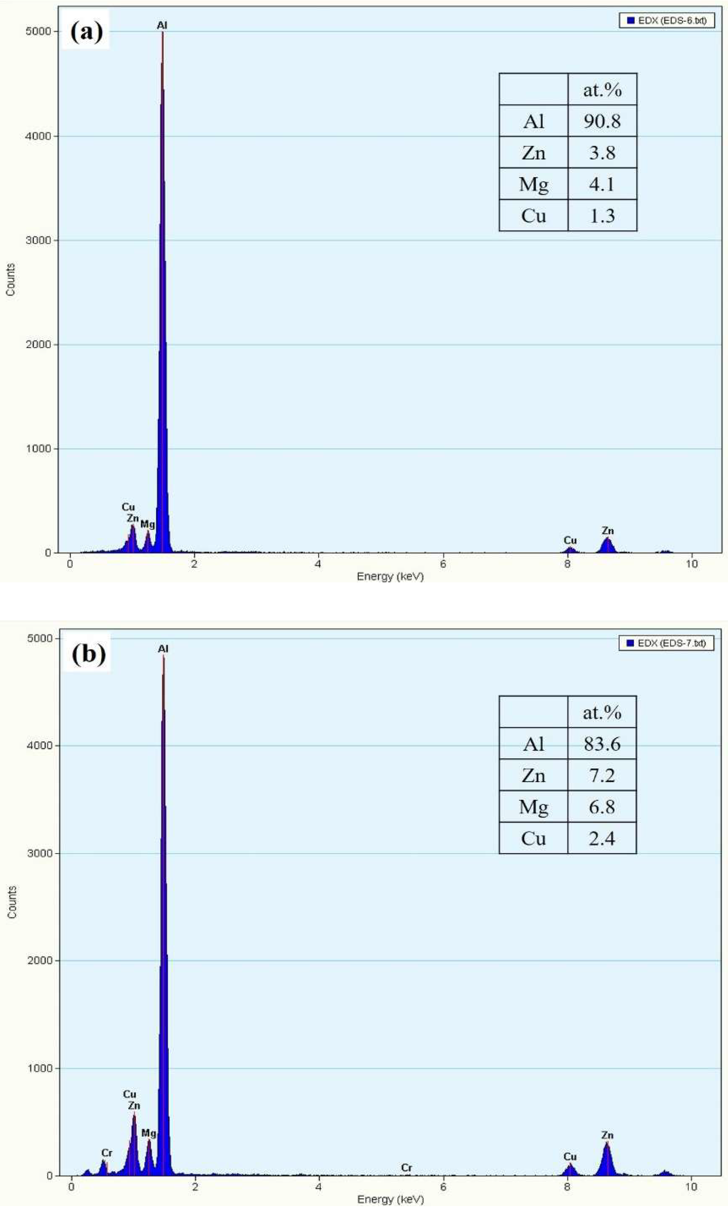
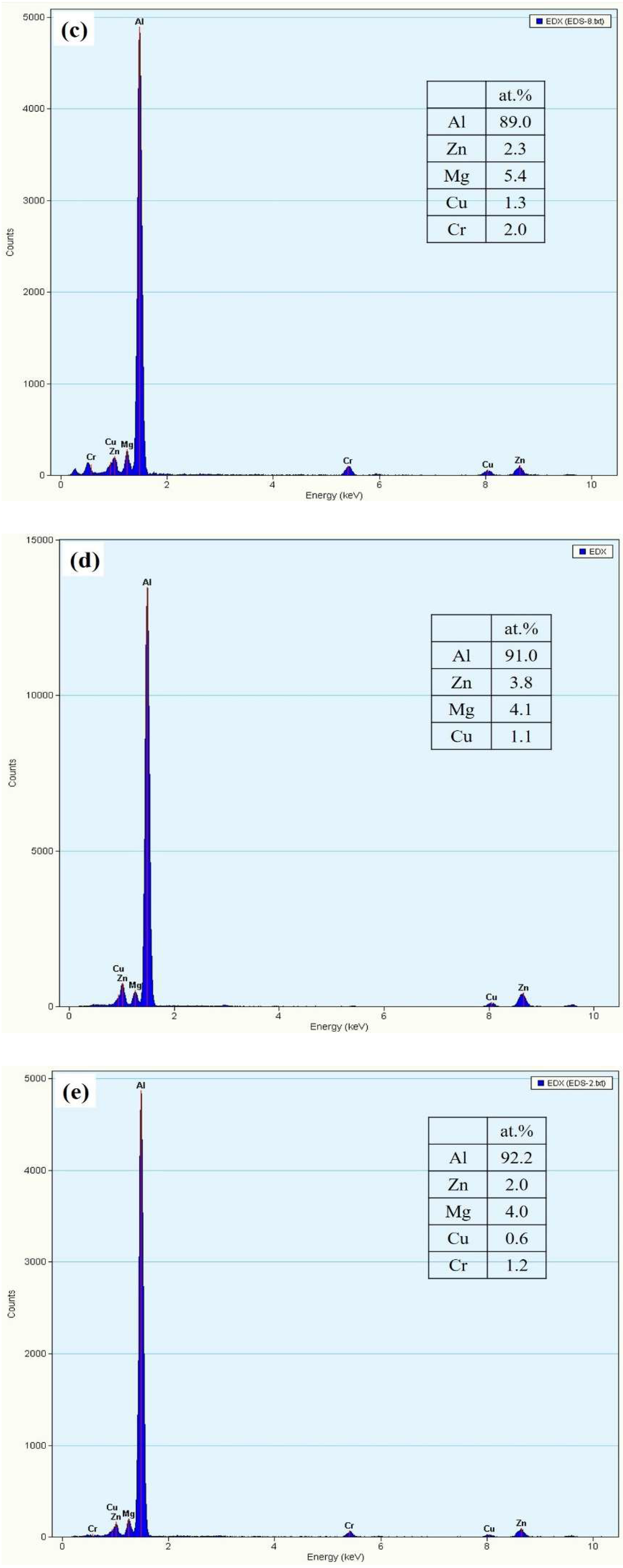
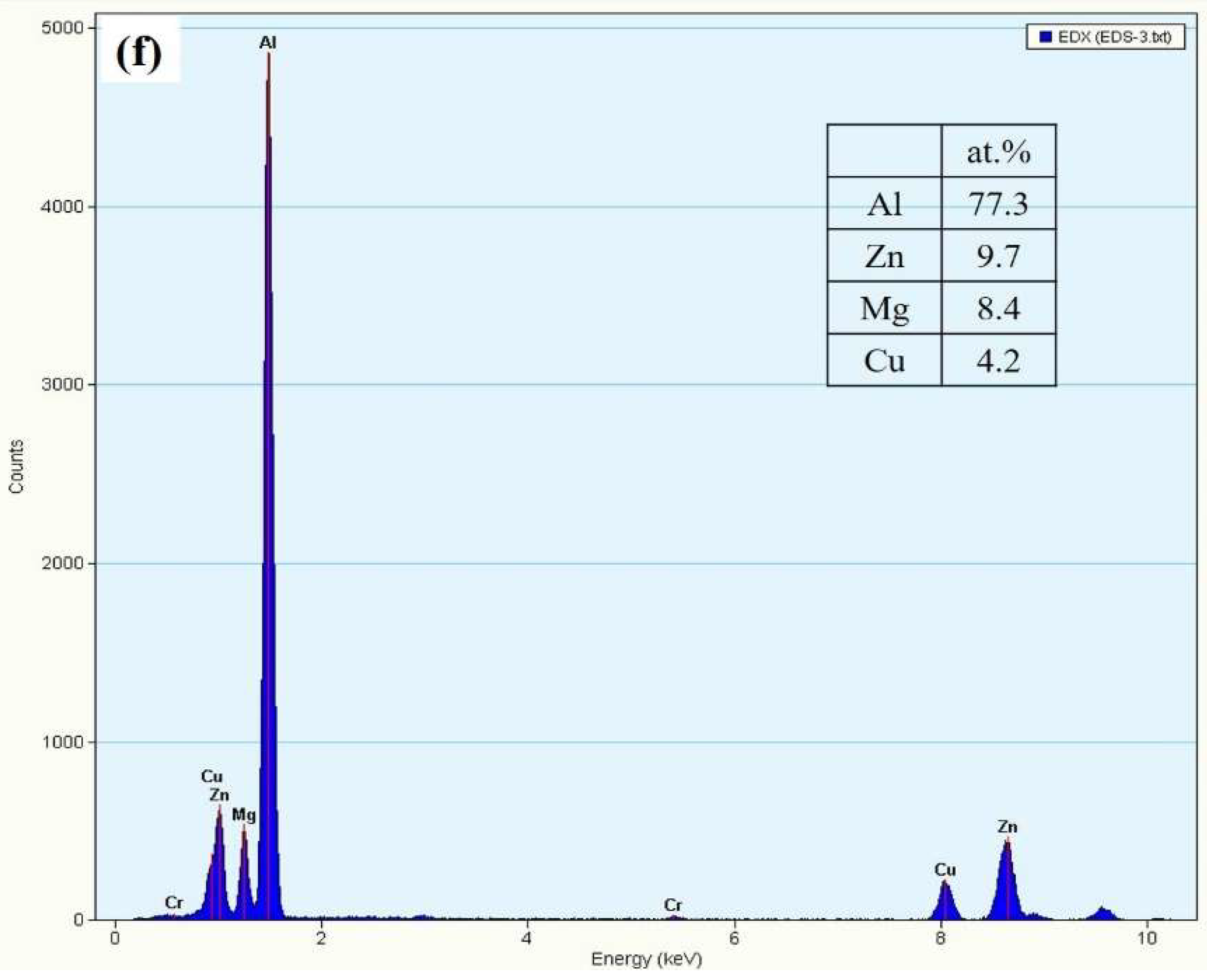
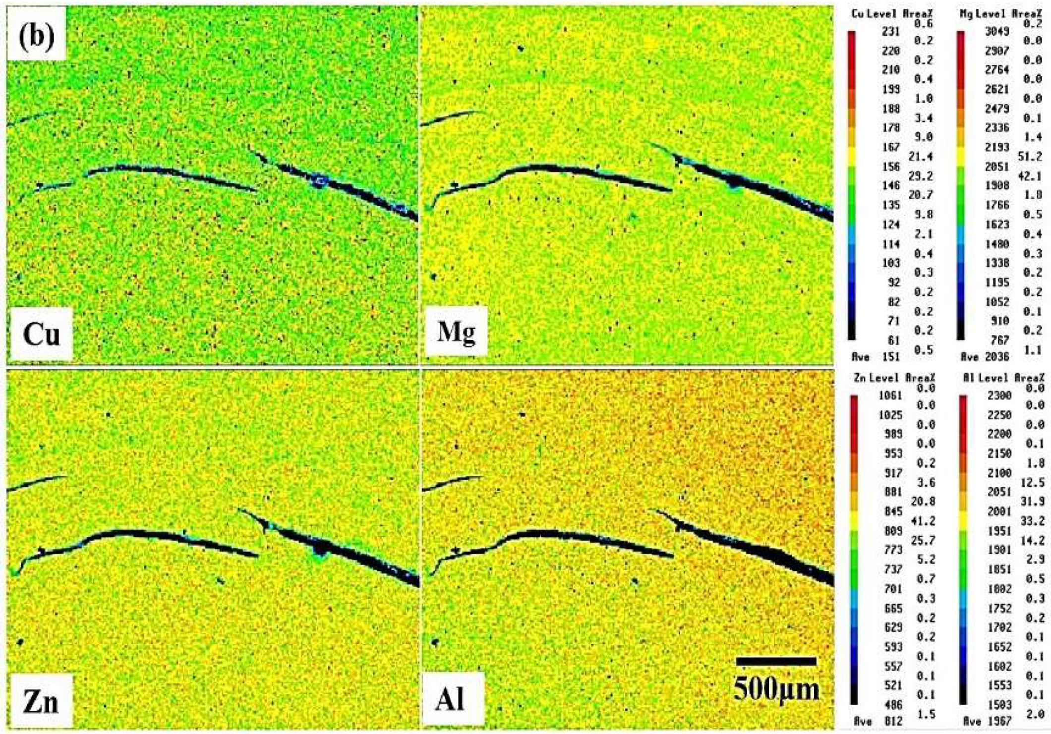
- The intermetallic particles were frequently found in the microstructure observations of the specimens that were friction stirred at various rotational speeds. The intermetallic particles were segregated along the string metal flow. However, in the hyper-rotational speed region, the FSIBs were accompanied by the discontinuous intermetallic particles and micro-voids were found due to the excess heat-input.
- This study clarified that the main reason behind the embrittlement during tensile deformation was the interaction between the precipitates, the FSIB and the micro-voids after aging with the hardening treatment.
Author Contributions
Funding
Acknowledgments
Conflicts of Interest
References
- Starke, E.A., Jr.; Staley, J.T. Application of modern aluminum alloys to aircraft. Prog. Aerosp. Sci. 1996, 32, 131–172. [Google Scholar] [CrossRef]
- Liu, J. Advanced Aluminum and Hybrid Aerostructures for Future Aircraft. Mater. Sci. Forum 2006, 521, 1233–1238. [Google Scholar] [CrossRef]
- Rajan, R.; Kah, P.; Mvola, B.; Martikainen, J. Trends in aluminium alloy development and their joining methods. Rev. Adv. Mater. Sci. 2016, 44, 383–397. [Google Scholar]
- Madhusudhan Reddy, G.; Gokhale, A.A.; Prasad Rao, K. Weld microstructure refinement in a 1441 grade aluminium-lithium alloy. J. Mater. Sci. 1997, 32, 4117–4126. [Google Scholar] [CrossRef]
- Thomas, W.M.; Nicholas, E.D.; Needham, J.D.; Murch, M.G.; Templesmith, P.; Dawes, C.J. Improvements to Friction Welding. GB Patent Application No. 9125978.8, December 1991. [Google Scholar]
- Mishra, R.S.; Mahoney, M.W. Friction Stir Welding and Processing; ASM International: Novelty, OH, USA, 2007; pp. 309–350. [Google Scholar]
- Ma, Z.Y. Friction Stir Processing Technology: A Review. Metall. Mater. Trans. A 2008, 39, 642–658. [Google Scholar] [CrossRef]
- Jata, K.V.; Semiatin, S.L. Continuous Dynamic Recrystallization During Friction Stir Welding of High Strength Aluminum Alloys. Scr. Mater. 2000, 43, 743–749. [Google Scholar] [CrossRef]
- Su, J.Q.; Nelson, T.W.; Mahoney, M.W. Microstructural investigation of friction stir welded 7075-T651 aluminum. Acta Mater. 2003, 51, 713–729. [Google Scholar] [CrossRef]
- Fratini, L.; Buffa, G.; Palmeri, D.; Hua, J.; Shivpuri, R. Material Flow in FSW of 7075-T6 Butt Joints: Continuous Dynamic Recrystallization Phenomena. J. Eng. Mater. Technol. 2006, 128, 428–435. [Google Scholar] [CrossRef]
- Moghaddam, M.; Zarei-Hanzaki, A.; Pishbin, M.H.; Shafieizad, A.H.; Oliveira, V.B. Characterization of the microstructure, texture and mechanical properties of 7075 aluminum alloy in early stage of severe plastic deformation. Mater. Charact. 2016, 119, 137–147. [Google Scholar] [CrossRef]
- Zhang, W.; Ding, H.; Cai, M.; Yang, W.; Li, J. Ultra-grain refinement and enhanced low-temperature superplasticity in a friction stir-processed Ti-6Al-4V alloy. Metall. Mater. Trans. A 2018, 727, 90–96. [Google Scholar] [CrossRef]
- Ma, Z.Y.; Mishra, R.S.; Mahoney, M.W. Superplastic deformation behaviour of friction stir processed 7075Al alloy. Acta Mater. 2002, 50, 4419–4430. [Google Scholar] [CrossRef]
- Mahmoud, T.S.; Gaafer, A.M.; Khalifa, T.A. Effect of tool rotational and welding speeds on microstructural and mechanical characteristics of friction stir welded A319 cast alloy. Mater. Sci. Technol. 2008, 24, 553–559. [Google Scholar] [CrossRef]
- Wang, Q.; Zhao, Z.; Zhao, Y.; Yan, K.; Liu, C.; Zhang, H. The strengthening mechanism of spray forming Al-Zn-Mg-Cu alloy by underwater friction stir welding. Mater. Des. 2016, 102, 91–99. [Google Scholar] [CrossRef]
- Nadammal, N.; Kailas, S.V.; Sazunar, J.; Suwas, S. Development of microstructure and texture during single and multiple pass friction stir processing of a strain hardenable aluminium alloy. Mater. Charact. 2018, 140, 134–146. [Google Scholar] [CrossRef]
- Orozco-Caballero, A.; Álvarez-Leal, M.; Verdera, D.; Rey, P.; Ruano, O.A.; Carreño, F. Evaluation of mechanical anisotropy and the deformation mechanism in a multi-pass friction stir processed Al-Zn-Mg-Cu alloy. Mater. Des. 2017, 125, 116–125. [Google Scholar] [CrossRef]
- Charit, I.; Mishra, R.S.; Mahoney, M.W. Multi-sheet structures in 7475 aluminum by friction stir welding in concert with post-weld superplastic forming. Scr. Mater. 2002, 47, 631–636. [Google Scholar] [CrossRef]
- Johannes, L.B.; Mishra, R.S. Multiple Passes of Friction Stir Processing for the creation of Superplastic 7075 Aluminum. Mater. Sci. Eng. A 2007, 464, 255–260. [Google Scholar] [CrossRef]
- Chegeni, A.A.; Kapranos, P. A microstructural evaluation of friction stir welded 7075 aluminum rolled plate heat treated to the semi-solid state. Metals 2018, 8, 41. [Google Scholar] [CrossRef]
- Al-Fadhalah, K.; Asi, F. Aging behavior of aluminum alloy 6082 subjected to friction stir processing. Crystals 2018, 8, 337. [Google Scholar] [CrossRef]
- Barbini, A.; Carstensen, J.; Santos, J.F.D. Influence of a non-rotating shoulder on heat generation, microstructure and mechanical properties of dissimilar AA2024/AA7075 FSW joints. J. Mater. Sci. Technol. 2018, 34, 119–127. [Google Scholar] [CrossRef]
- Yang, B.; Yan, J.; Sutton, M.A.; Reynolds, A.P. Banded microstructure in AA2024-T351 and AA2524-T351 aluminum friction stir welds Part I. Metallurgical studies. Mater. Sci. Eng. A 2004, 364, 55–65. [Google Scholar] [CrossRef]
- Rajakumar, S.; Muralidharan, C.; Balasubramanian, V. Influence of friction stir welding process and tool parameters on strength properties of 7075-T6 aluminium alloy joints. Mater. Des. 2011, 32, 535–549. [Google Scholar] [CrossRef]
- Elangovan, K.; Balasubramanian, V. Influences of pin profile and rotational speed of the tool on the formation of friction stir processing zone in AA2219 aluminium alloy. Mater. Sci. Eng. A 2007, 459, 7–18. [Google Scholar] [CrossRef]
- Ku, M.H.; Hung, F.Y.; Lui, T.S.; Chen, L.H. Embrittlement Mechanism on Tensile Fracture of 7075 Al Alloy with Friction Stir Process (FSP). Mater. Trans. 2011, 52, 112–117. [Google Scholar] [CrossRef]
- Frigaard, Ø.; Grong, Ø.; Midling, O.T. Modelling of heat flow phenomena in friction stir welding of aluminium alloys. In Proceedings of the Seventh International Conference Joints in Aluminum—INALCO ’98, Cambridge, UK, 15–17 April 1998. [Google Scholar]
- Kumar, A.; Godasu, A.K.; Pal, K.; Mula, S. Effect of in-process cryocooling on metallurgical and mechanical properties of friction stir processed Al7075 alloy. Mater. Charact. 2018, 144, 440–447. [Google Scholar] [CrossRef]


| Zn | Mg | Cu | Cr | Fe | Ti | Si | Mn | Al |
|---|---|---|---|---|---|---|---|---|
| 5.67 | 2.44 | 1.71 | 0.26 | 0.16 | 0.02 | 0.05 | 0.01 | Bal |
| No. | Al | Zn | Mg | Cu | Fe |
|---|---|---|---|---|---|
| A | 72.0 | 0 | 0 | 18.7 | 9.3 |
| B | 73.4 | 0 | 0 | 17.3 | 9.3 |
| C | 57.9 | 0 | 0 | 34.3 | 7.8 |
| D | 94.9 | 2.8 | 2.3 | 0 | 0 |
© 2019 by the authors. Licensee MDPI, Basel, Switzerland. This article is an open access article distributed under the terms and conditions of the Creative Commons Attribution (CC BY) license (http://creativecommons.org/licenses/by/4.0/).
Share and Cite
Ku, M.-H.; Hung, F.-Y.; Lui, T.-S. Embrittlement Due to Excess Heat Input into Friction Stir Processed 7075 Alloy. Materials 2019, 12, 227. https://doi.org/10.3390/ma12020227
Ku M-H, Hung F-Y, Lui T-S. Embrittlement Due to Excess Heat Input into Friction Stir Processed 7075 Alloy. Materials. 2019; 12(2):227. https://doi.org/10.3390/ma12020227
Chicago/Turabian StyleKu, Ming-Hsiang, Fei-Yi Hung, and Truan-Sheng Lui. 2019. "Embrittlement Due to Excess Heat Input into Friction Stir Processed 7075 Alloy" Materials 12, no. 2: 227. https://doi.org/10.3390/ma12020227
APA StyleKu, M.-H., Hung, F.-Y., & Lui, T.-S. (2019). Embrittlement Due to Excess Heat Input into Friction Stir Processed 7075 Alloy. Materials, 12(2), 227. https://doi.org/10.3390/ma12020227