Effects of Filler Distribution on Magnetorheological Silicon-Based Composites


1
Institute of Physics of Czech Academy of Science, Na Slovance 1999/2, 18221 Prague 8, Czech Republic
2
The Institute for Nanomaterials, Advanced Technology and Innovation, Technical University of Liberec, Studentska 2, 46117 Liberec, Czech Republic
3
Department of Civil Engineering and Architecture, University of Catania an UdR-Catania Consorzio INSTM, Viale Andrea Doria 6, 95125 Catania, Italy
*
Authors to whom correspondence should be addressed.
Materials 2019, 12(18), 3017; https://doi.org/10.3390/ma12183017
Submission received: 17 July 2019
/
Revised: 3 September 2019
/
Accepted: 12 September 2019
/
Published: 18 September 2019
(This article belongs to the Special Issue Green Composites: Preparation, Properties, and Applications)
Abstract
:The smart materials subclass of magnetorheological elastomer (MRE) composites is presented in this work, which aimed to investigate the influence of filler distribution on surface morphology. Iron particles with sizes ranging from 20 to 150 µm were incorporated into the elastomer matrix and a 30% volume fraction (V%) was chosen as the optimal quantity for the filler amount in the elastomer composite. The surface morphology of MRE composites was examined by 3D micro-computed tomography (µCT) and scanning electron microscopy (SEM) techniques. Isotropic and anisotropic distributions of the iron particles were estimated in the magnetorheological elastomer composites. The filler particle distribution at various heights of the MRE composites was examined. The isotropic distribution of filler particles was observed without any influence from the magnetic field during sample preparation. The anisotropic arrangement of iron fillers within the MRE composites was observed in the presence of a magnetic field during fabrication. It was shown that the linear arrangement of the iron particle chain induced magnetization within the composite. Simulation analysis was also performed to predict the particle distribution of magnetization in the MREs and make a comparison with the experimental observations.

1. Introduction
Materials scientists, taking advantage of the best properties of each component and trying to decrease or eliminate their drawbacks, define composites as the material platform of the twenty-first century [1], where two or more components are combined in a single material to give new and previously unattainable combinations of useful properties [2,3].
Magnetorheological elastomer (MRE) composites belong to the category of smart materials, whose properties can be significantly altered by controlled external stimuli, such as stress, temperature, pH, moisture, and electric or magnetic fields [4,5,6,7,8,9]. Elastomers comprising a matrix interspersed with micron-sized ferromagnetic particles are known as MREs, being analogs to magnetorheological (MR) fluids [10]. The rheological properties, namely deformation and flow behavior under stress, of MREs can be altered by the application of an external magnetic field. The characteristic response depends on many factors, including the nature of the matrix, the size, distribution, composition, and quantity of the ferromagnetic particles, and whether the ferromagnetic particles are aligned in chains or randomly dispersed [11]. Besides magnetically controlled smart materials, magnetic composites such as MREs and MR fluids have also demonstrated a high potential for damper applications, especially if the magnetic field generation can be configured to produce lightweight and flexible devices for shock absorption in damping capacitors [12,13,14]. Owing to benefits that include low mass, flexibility, no geometric constraints, cost-effectiveness, and miniaturization, soft actuators configured in a thin film are potentially available for use in various sectors [15,16].
MRE composites consist of two phases, namely magneto-active filler and non-magnetic soft elastomer matrix. The shape and size of the used particles are generally chosen based on the induced magnetization in the MRE composites [17]. The particle–particle interaction within the matrix, when exposed to an external magnetic field, plays a key role in the elastic properties of the composite, thus determining the overall properties and performance of the MRE composites as smart materials [18,19]. The induced magnetic particle–particle interactions strongly depend on the particle distribution within the matrix, thus being influenced by their nearest position and arrangement inside the composites [20,21]. The mechanical properties of the MRE composites, in particular, are highly influenced by the isotropic and/or anisotropic (chain-like, plane-like) distribution of the particles within the matrix [22], depending on the method of preparation [23]. Various research studies have been published concerning the MREs’ properties [24,25,26,27,28], but only a limited number of them speculate about the internal structure of the composites, such as the influence of the particle shape and size and their distribution with and without the presence of an external magnetic field during the fabrication process [29,30,31]. Particle interactions at the microscopic level can alter the macroscopic properties of MRE composites, especially in the presence of an external magnetic field, thus influencing their mechanical properties. The aim of this work was to investigate the 3D internal structure of the MRE composites, with the use or not of a magnetic field during the preparation, by using 3D micro-computed tomography (µCT). Furthermore, the surface morphology and filler distribution within the MRE composites were investigated by scanning electron microscopy (SEM), and both isotropic and anisotropic filler arrangements were evaluated. Finally, to predict the particle distribution in the composite, a simulation mechanism of the magnetic behavior was proposed and compared with the experimental observations.
2. Experimental Section
2.1. Materials
The first elastomer matrix (A) was obtained by the reaction of a commercial silicone rubber Lukopren N 1522 (Lucební závody, Kolín, Czech Republic) and tetraethyl silicate (TEOS) (Sigma-Aldrich Co., St. Gallen, Switzerland) in the presence of dibutyltin dilaurate (DBTD) (Sigma-Aldrich Co., St. Gallen, Switzerland). The second matrix (B) was prepared by reacting two different silicone rubbers, namely RTV 5532A (Elantas, Collecchio, Italy) and ZA 22 (Mouldlife, Suffolk, UK). Magneto-active fillers such as iron particles (Havel Composites CZ s.r.o., Olomoucky Kraj, Czech Republic) were chosen with an irregular size from 20 to 150 µm (purity >95%).
2.2. Techniques
The iron particle distribution and adhesion within the elastomer matrix were examined inside the microstructure of the MRE composites by scanning electron microscopy (Model TM-3000, Hitachi High Technologies Corporation, Tokyo, Japan). The internal structure and 3D images of the MRE composites were observed by micro-computed tomography (Bruker, Kontich, Belgium). The anisotropic distribution of the filler particles within the matrix was estimated through the simulation (MSC MARC software 2018, MSC Software GmbH, Munich, Germany) of the MRE composite in the presence of a magnetic field. The results obtained from the simulation were compared with those obtained experimentally for the MRE samples fabricated in the presence of an external magnetic field. The internal structure of the composites and their mechanism towards a self-assembled structure in isotropic behavior and small chain structures in anisotropic behavior were well examined.
2.3. Composite Preparation
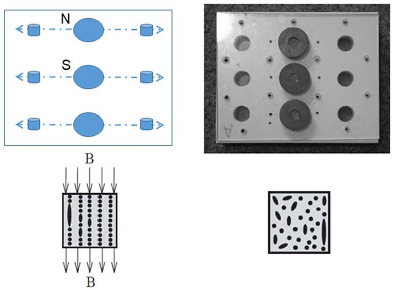
According to a suggestion in the literature [32], a volume fraction (V%) equal to 30% was chosen as the optimal filler quantity for the incorporation into the matrix. The elastomers were mixed with the iron powder at room temperature and then held under vacuum (20 KPa) for 12 h. Silicone oil was used as a binder and coupling agent. The obtained composites were removed from the mold after 24 h and then cured at 80 °C for another 24 h. Their composition and polarizable character are reported in Table 1. The iron particle distribution is presented in Figure 1, showing an average particle size of approximately 50 µm. The isotropic and anisotropic distributions of the fillers within the MRE during fabrication are presented in the schematic diagram (Figure 2a–d).
3. Results and Discussion
3.1. Internal Image of the MRE Composite using 3D Image Acquisition
The internal image of the elastomer matrices (A and B) and their respective MRE composites with isotropic filler distribution are reported in Figure 3, where their 3D constructions with a representative volume of the elements are shown.
The internal areas show the uniform embodiment of iron particles within the composite’s matrix; however, porosities can be also observed in some of them. Slices from the overall 3D images are presented in Figure 4, where the 2D image of the XY pattern shows the isotropic and anisotropic effects within the MRE composites. The isotropic one resulted in a homogenous and uniform distribution of the filler particles with the frame of the MRE composites (Figure 4a,b), whereas for the anisotropic behavior the influence of the magnetic field results in voids inside the composites (Figure 4c,d).
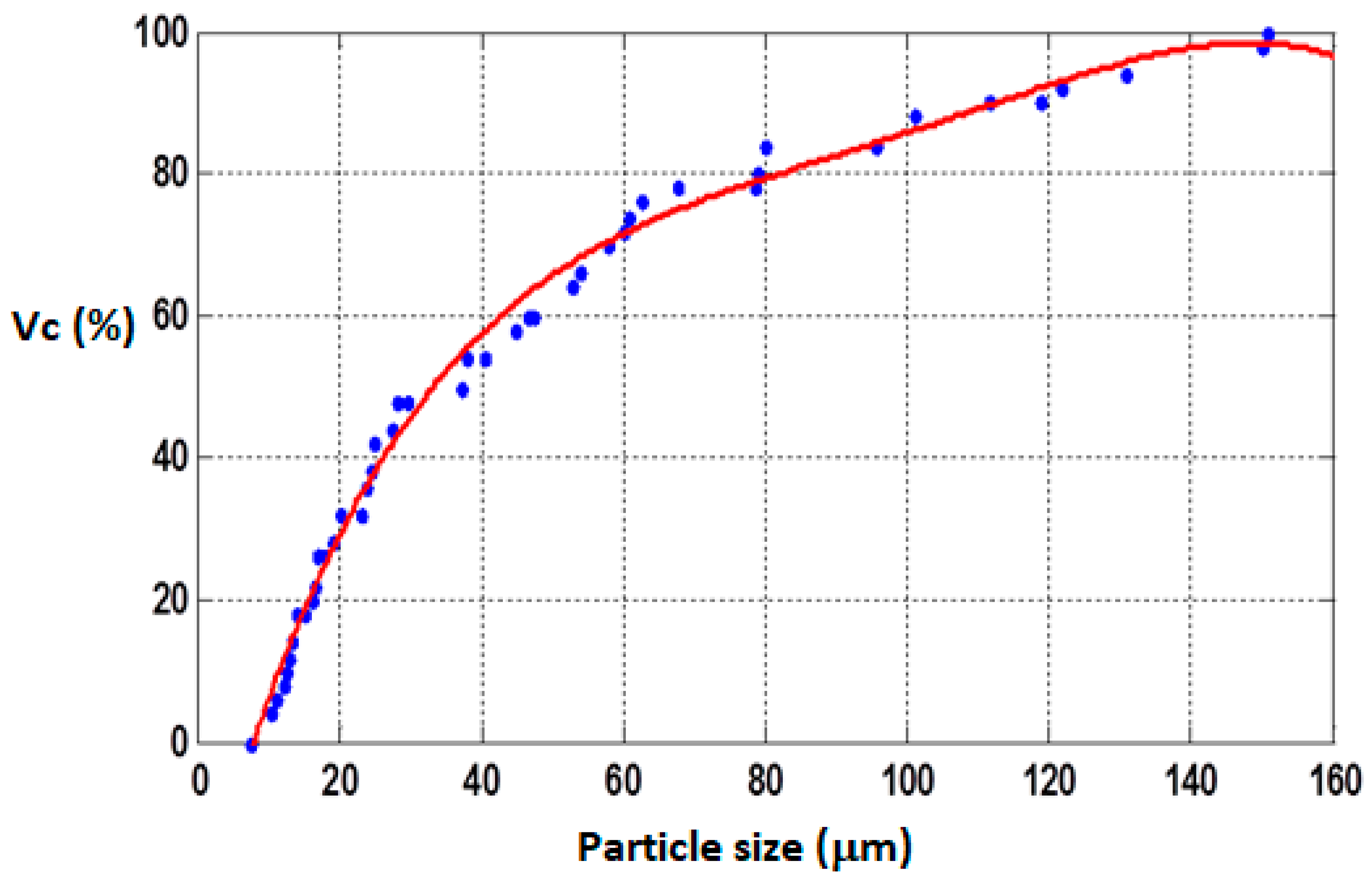
As shown, the particle distribution is in the micron scale and the composite density obeys the following equation [32]:
where ρc and Vc represent the composite density and volume; ρf and Vf are the filler density and volume; ρm and Vm are the matrix density and volume; and ρv and Vv the void density and volume, respectively. When the void density is negligible, ρv ~ 0, and thus Equation (1) can be modified into the following equation:
Because the volume of the filler amount remains constant, the volume of the matrix varies based on the filler content, as follows:
and, depending upon the void volume, Equation (3) can be further modified. Thus, the overall quality of the internal structure is a function of the filler distribution within the MRE composite’s matrix.
3.2. Distribution of Iron Particles within the MRE Composite
In Figure 5, SEM images of the MRE composites, prepared in the presence (Figure 5a,b) and absence (Figure 5c,d) of a magnetic field, are shown. When we applied a magnetic field during the preparation, we observed an isotropic distribution without any porosity, whereas for the composite prepared without this application, anisotropic distribution was evident. In this latter composite, porosity is observed towards its edge, which may be due to the aligned magnetic forces, resulting in the creation of voids.
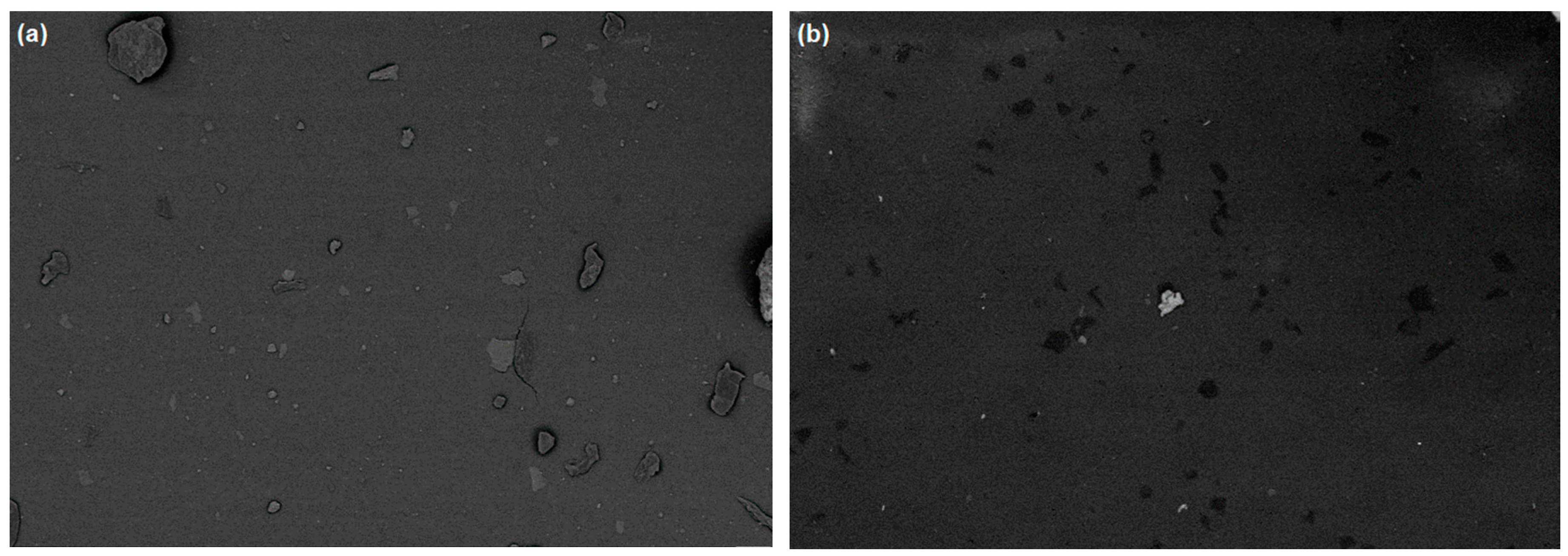
In order to better analyze the iron particle distribution within the elastomeric matrices, the samples were cut at various heights from the top, middle, and bottom positions. SEM images of the top layer showed less particle distribution within the composites (Figure 6a,b).
3.3. Analysis of the Iron Particle Distribution along the MRE Composites
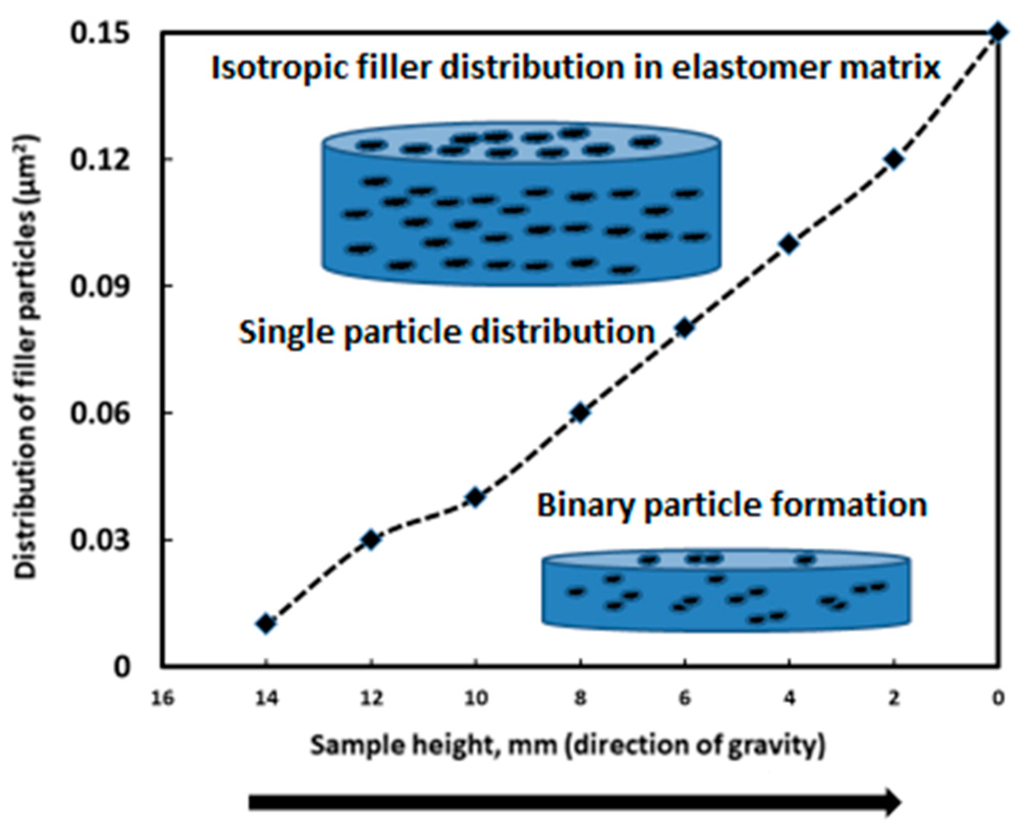
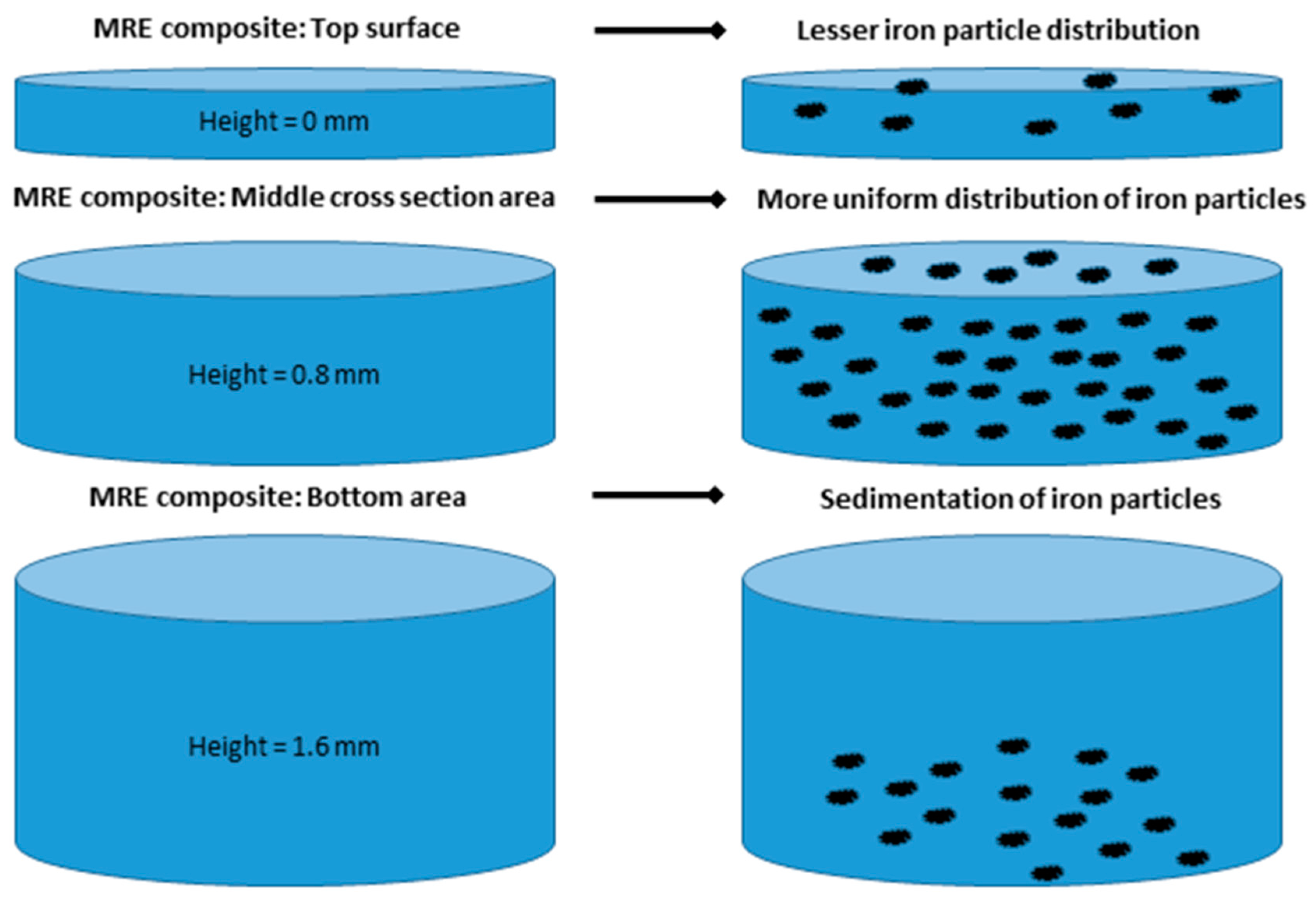
The distribution profile of iron particles as a function of the height of the MRE composite was calculated, showing the filler mostly settled down towards the base of the composite, whereas fewer particles were present towards the upper position. The single particle distribution in the elastomeric composite versus the binary particle distribution in its surface area is plotted in Figure 9.
The binary particle distribution is more pronounced along the base of the composite and the volume fraction is less in comparison to the single isotropic filler distribution. Cutting the MRE composite into three pieces (top, middle, and bottom positions) led us to hypothesize a schematic filler distribution within the different composite layers (Figure 10).
The distribution of iron particles within the MRE composites showed a smaller amount at the surface and a uniform distribution within the middle cross-section area. Finally, the bottom area showed the binary combination of particles settled on the base of the composite.
3.4. Simulation Analysis and Anisotropic Filler Distribution within the MRE Composite
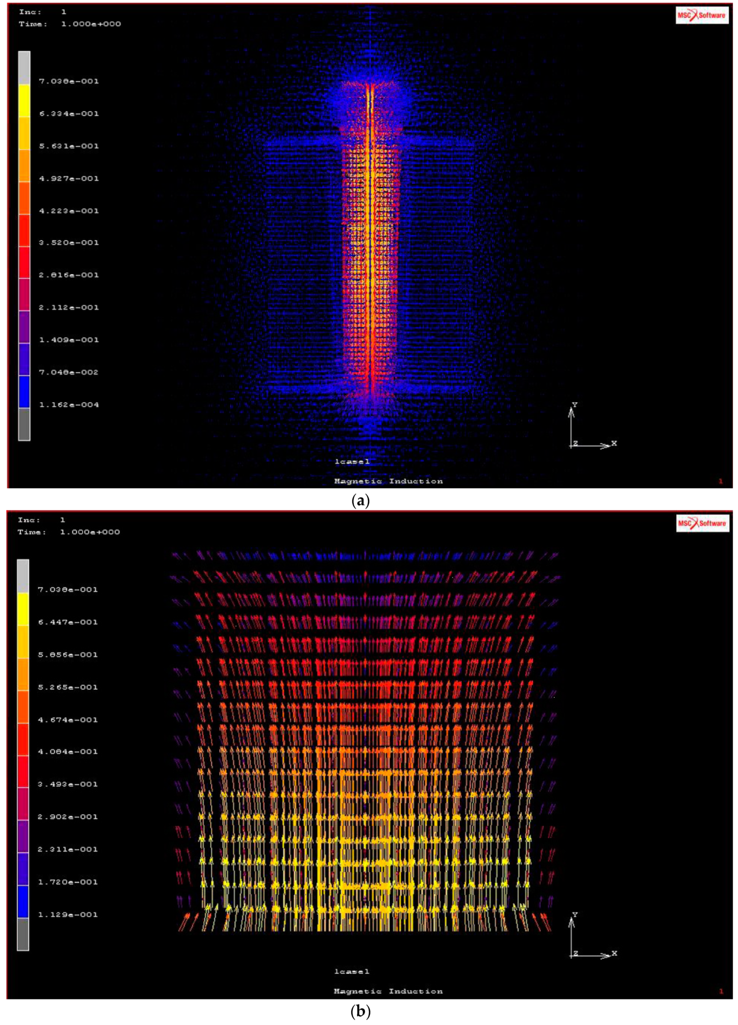
A simulation analysis in the presence of a magnetic field was carried out, and the magnetic induction generated in the MRE composite, at outer and inner positions, is presented in Figure 11.
The magnetic induction B calculated at the outer and inner edges show values of 0.478 and 0.700 T, respectively (Table S1, Supplementary Materials). The magnetic induction distribution around a coil, with a sample position on the top, and the magnetic induction inside the MRE composite are reported in Figure 12, respectively, showing a linear uniform flow of the magnetic field from the lower to the upper regions of the composite. Furthermore, the theoretical prediction of the magnetic force and induction at various magnetic current values and various positions of compression values are reported in Figures S1 and S2 (Supplementary Materials).
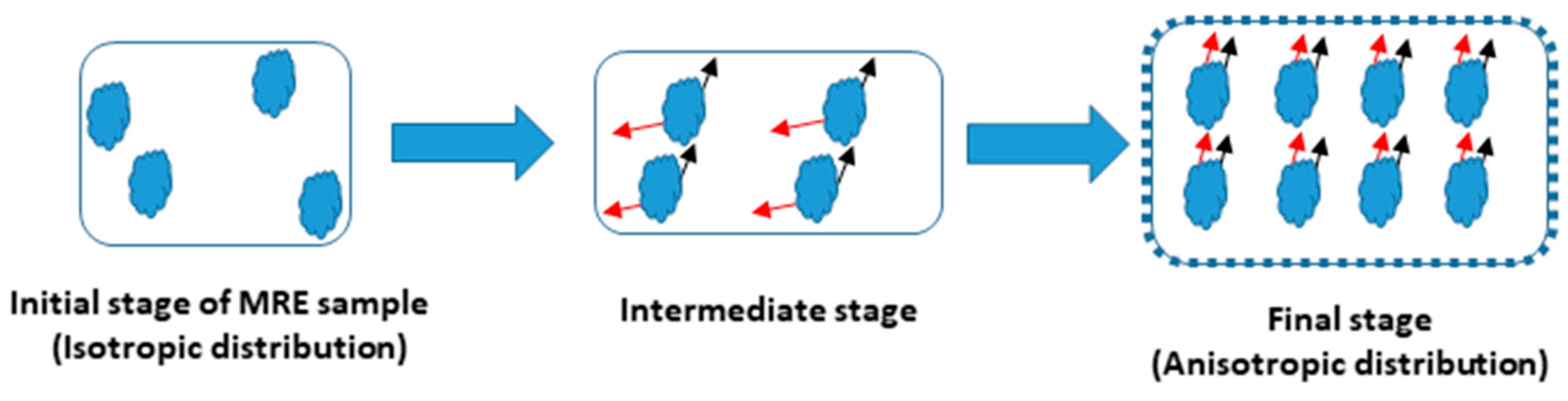
The presence of a magnetic field leads to an anisotropic distribution of the iron particles within the MRE composite, resulting in small linear chains of particles such as fibrils arranged perpendicularly within the normal axis matrix [33]. In addition, the presence of the magnetic field induces magnetic forces to create small voids along the edge of the composite. Upon anisotropic distribution, an alignment of iron particles within the matrix was observed and the dipolar axis related to the magnetization followed one direction, which is different from the isotropic distribution in which the magnetic dipolar forces were randomly oriented within the composite. The internal forces between two particles result in the combined coherent forces due to the surface energy effect. Otherwise, self-assembled structures lead towards the magnetization in the MRE composite.
A schematic diagram of this phenomenon is shown in Figure 13:
1. The initial stage of the MRE composite, without the presence of a magnetic field, shows a random distribution of iron particles within the matrix;
2. Applying a magnetic field, perpendicular to the surface of the composite, results in the development of dipolar magnetization in the particles;
4. Conclusions
The internal structure of MRE composites was studied, showing isotropic and anisotropic distributions of the iron particles within the elastomeric matrix, whose quantity and nature (magneto-active) influenced the mechanical and magnetic properties of the obtained material. The effect of particle distribution within the composites was investigated at various heights, showing a different behavior from the top to the bottom of the samples. The top surface showed a lesser distribution of the particles; however, the middle and bottom surfaces showed particle sedimentation within the composite volume for micron-sized ones. The sedimentation was less for smaller-sized particles, resulting in a more uniform distribution. The anisotropic filler alignment was explained on the basis of the iron particle interaction, due to the magnetic induction. This latter, as it has been seen, leads to the formation of particle chains as fibrils within the matrix. Thus, the dipolar interaction between two particles within an isotropic distribution presentation plays a key role in the magnetic behavior of the MRE composite. The maximum magnetic induction of 0.659 T was achieved at a magnetic current value of 7 A for the MRE composite during the compression analysis.
Supplementary Materials
The following are available online at https://www.mdpi.com/1996-1944/12/18/3017/s1. Figure S1: Magnetic forces theoretical prediction using various magnetic currents as a function of compression shift position, Figure S2: Magnetic inductions theoretical prediction using various magnetic currents as a function of compression shift position, Figure S3: Carbonyl iron (CI) particles of size range 1–5 μm within the MRE composite, Table S1: Measured values of magnetic force and induction at various current and compression position of the magnetorheological elastomer (MRE) composites.
Author Contributions
S.S. and M.Š. designed and carried out the experimental session; S.S. analyzed the data; and I.B. wrote the paper.
Funding
Ignazio Blanco is grateful to the MIUR for the grant “Fund for basic research activities” and to the Department of Civil Engineering and Architecture of the University of Catania for supporting the project MATErials LIfe foreCAst (MATELICA).
Conflicts of Interest
The authors declare no conflict of interest.
References
- Blanco, I. The Rediscovery of POSS: A Molecule Rather than a Filler. Polymers 2018, 10, 904. [Google Scholar] [CrossRef] [PubMed]
- Cavallaro, G.; Lazzara, G.; Milioto, S.; Parisi, F.; Sparacino, V. Thermal and dynamic mechanical properties of beeswax-halloysite nanocomposites for consolidating waterlogged archaeological woods. Polym. Degrad. Stab. 2015, 120, 220–225. [Google Scholar] [CrossRef]
- Cavallaro, G.; Lazzara, G.; Konnova, S.; Fakhrullin, R.; Lvov, Y. Composite films of natural clay nanotubes with cellulose and chitosan. Green Mat. 2014, 232–242. [Google Scholar] [CrossRef]
- Samal, S.; Vlacha, J.; Kavana, P. Improved mechanical properties of magneto rheological elastomeric composite with isotropic iron filler distribution. Ciênc. Tecnol. Mater. 2016, 28, 155–161. [Google Scholar] [CrossRef]
- Carlson, J.D.; Jolly, M.R. MR fluid, foam and elastomer devices. Mechatronics 2000, 10, 555–569. [Google Scholar] [CrossRef]
- Ginder, J.M.; Nichols, M.E.; Elie, L.D.; Tardiff, J.L. Magnetorheological elastomers: Properties and applications. In Proceedings of the 1999 Symposium on Smart Structures and Materials, Newport Beach, CA, USA, 1 March 1999; SPIE: Bellingham, WA, USA, 1999; Volume 3675, pp. 131–138. [Google Scholar]
- Puente-Córdova, J.G.; Reyes-Melo, M.E.; Palacios-Pineda, L.M.; Martínez-Perales, I.A.; Martínez-Romero, O.; Elías-Zúñiga, A. Fabrication and characterization of isotropic and anisotropic magnetorheological elastomers, based on silicone rubber and carbonyl iron microparticles. Polymers 2018, 10, 1343. [Google Scholar] [CrossRef]
- Siti Aishah Binti, A.A.; Saiful, A.M.; Nur, A.N.; Nor Azlin, N.A.R.; Ubaidillah, U.; Seung-Bok, C.; Norzilawati, M. Material characterization of magnetorheological elastomers with corroded carbonyl iron particles: Morphological images and field-dependent viscoelastic properties. Int. J. Mol. Sci. 2019, 20, 3311. [Google Scholar]
- Nurul, A.Y.; Saiful, A.M.; Ubaidillah; Siti Aishah, A.A.; Salihah, T.S.; Nurul, A.A.W. Thermal Stability and Rheological Properties of Epoxidized Natural Rubber-Based Magnetorheological Elastomer. Int. J. Mol. Sci. 2019, 20, 746. [Google Scholar]
- Hu, Y.; Wang, Y.L.; Gong, X.L.; Gong, X.Q.; Zhang, X.Z.; Jiang, W.Q.; Zhang, P.Q.; Chen, Z.Y. New magnetorheological elastomers based on polyurethane/Si-rubber hybrid. Polym. Test. 2005, 24, 324–329. [Google Scholar] [CrossRef]
- Jolly, M.R.; Carlson, J.D.; Munoz, B.C.; Bullions, T.A. The magnetoviscoelastic effect of elastomer composites consisting of ferrous particles embedded in a polymer matrix. J. Intell. Mater. Syst. Struct. 1996, 7, 613–622. [Google Scholar] [CrossRef]
- Balasoiu, M.; Bica, I. Composite magnetorheological elastomers as dielectrics for plane capacitors: Effects of magnetic field intensity. Results Phys. 2016, 6, 199–202. [Google Scholar] [CrossRef] [Green Version]
- Bica, I.; Anitas, E.M.; Averis, L.M.E. Tensions and deformations in composites based on polyurethane elastomer and magnetorheological suspension: Effects of the magnetic field. J. Ind. Eng. Chem. 2015, 28, 86–90. [Google Scholar] [CrossRef]
- Bunoiu, M.; Bica, I. Magnetorheological elastomer based on silicone rubber, carbonyl iron and Rochelle salt: Effects of alternating electric and static magnetic fields intensities. J. Ind. Eng. Chem. 2016, 37, 312–318. [Google Scholar] [CrossRef]
- Shiga, T.; Okada, A.; Kurauchi, T. Magnetroviscoelastic behavior of composite gels. J. Appl. Polym. Sci. 1995, 58, 787–792. [Google Scholar] [CrossRef]
- Stepanov, G.V.; Borin, D.Y.; Raikher, L.Y.; Melenev, P.V.; Perov, N.S. Motion of ferroparticles inside the polymeric matrix in magnetoactive elastomers. J. Phys. Condens. Matter. 2008, 20, 204121. [Google Scholar] [CrossRef]
- Petríková, I.; Marvalová, B.; Samal, S.; Garmedia, X. Experimental Research of the Damping Properties of Magnetosensitive Elastomers. In Title of Constitutive Models for Rubber IX; Lion, A., Johlitz, M., Eds.; CRC Press: London, UK, 2015; pp. 1–8. [Google Scholar]
- Samal, S.; Vlach, J.; Kolinova, M.; Kavan, P. Micro-computed tomography characterization of isotropic filler distribution in magnetorheological elastomeric composites. In Title of Advanced Processing and Manufacturing Technologies for Nanostructured and Multifunctional Materials; Ohji, T., Singh, M., Halbig, M., Moon, K., Eds.; Wiley: Hoboken, NJ, USA, 2017; pp. 57–69. [Google Scholar]
- Yu, M.; Ju, B.; Fu, J.; Liu, X.; Yang, Q. Influence of composition of carbonyl iron particles on dynamic mechanical properties of magnetorheological elastomers. J. Magn. Magn. Mater. 2012, 324, 2147–2152. [Google Scholar] [CrossRef]
- Lokander, M.; Stenberg, B. Improving the magnetorheological effect in isotropic magnetorheological rubber materials. Polym. Test. 2003, 22, 677–680. [Google Scholar] [CrossRef]
- Sorokin, V.V.; Ecker, E.; Stepanov, G.V.; Shamonin, M.; Monkman, G.J.; Kramarenko, E.Y.; Khokhlovad, E.A.R. Experimental study of the magnetic field enhanced Payne effect in magnetorheological elastomers. Soft Matter. 2014, 10, 8765–8776. [Google Scholar] [CrossRef]
- Ivaneyko, D.; Toshchevikov, V.; Saphiannikova, M.; Heinrich, G. Mechanical properties of magneto-sensitive elastomers: Unification of the continuum-mechanics and microscopic theoretical approaches. Soft Matter. 2014, 10, 2213–2225. [Google Scholar] [CrossRef]
- Zhang, X.; Peng, S.; Wen, W.; Li, W. Analysis and fabrication of patterned magnetorheological elastomers. Smart Mater. Struct. 2008, 17, 045001. [Google Scholar] [CrossRef]
- Li, R.; Sun, L.Z. Dynamic mechanical behavior of magnetorheological nanocomposites filled with carbon nanotubes. Appl. Phys. Lett. 2011, 99, 131912. [Google Scholar] [CrossRef]
- Sutrisno, J.; Purwanto, A.; Mazlan, S.A. Recent progress on magnetorheological solids: Materials, fabrication, testing, and applications. Adv. Eng. Mater. 2015, 17, 563–597. [Google Scholar]
- Aziz, S.A.A.; Mazlan, S.A.; Ismail, N.I.N.; Ubaidillah, U.; Choi, S.B.; Khairi, M.H.A.; Yunus, N.A. Effects of multiwall carbon nanotubes on viscoelastic properties of magnetorheological elastomers. Smart Mater. Struct. 2016, 25, 077001. [Google Scholar] [CrossRef]
- Yu, Y.; Li, J.; Li, Y.; Li, S.; Li, H.; Wang, W. Comparative investigation of phenomenological modeling for hysteresis responses of magnetorheological elastomer devices. Int. J. Mol. Sci. 2019, 20, 3216. [Google Scholar] [CrossRef]
- Shabdin, M.K.; Rahman, M.A.A.; Mazlan, S.A.; Hapipi, N.M.; Adiputra, D.; Aziz, S.A.A.; Bahiuddin, I.; Choi, S.-B. Material characterizations of Gr-based magnetorheological elastomer for possible sensor applications: Rheological and resistivity properties. Materials 2019, 12, 391. [Google Scholar] [CrossRef]
- Rey, T.; Chagnon, G.; Le Cam, J.-B.; Favier, D. Effects of temperature on the mechanical behavior of filled and unfilled silicone rubbers. Available online: https://hal.archives-ouvertes.fr/hal-00936536 (accessed on 11 January 2014).
- Samal, S.; Kim, S.; Kim, H. Effects of filler size and distribution on viscous behavior of glass composites. J. Am. Ceram. Soc. 2012, 95, 1595–1603. [Google Scholar] [CrossRef]
- Seo, J.; Kim, S.; Samal, S.; Kim, H. Viscous Behaviour of Bi2O3-B2O3-Zno glass composites with ceramic fillers. Adv. Appl. Ceram. 2014, 113, 334–340. [Google Scholar] [CrossRef]
- Sorokin, V.V.; Stepanov, G.V.; Shamonin, M.; Monkman, G.J.; Kramarenko, E.Y. Hysteresis of the viscoelastic properties and the normal force in magnetically and mechanically soft magnetoactive elastomers: Effects of filler composition, strain amplitude and magnetic field. Polymer 2015, 76, 191–202. [Google Scholar] [CrossRef]
- Wang, Y.; Hu, Y.; Chen, L.; Gong, X.; Jiang, W.; Zhang, P.; Chen, Z. Effects of rubber/magnetic particle interactions on the performance of magnetorheological elastomers. Polym. Test. 2006, 25, 262–267. [Google Scholar] [CrossRef]
- Saxena, P.; Pelteret, J.P.; Steinmann, P. Modelling of iron-filled magneto-active polymers with a dispersed chain-like microstructure. Eur. J. Mech. A Solids. 2015, 50, 132–151. [Google Scholar] [CrossRef] [Green Version]
- Mehnert, M.; Hossain, M.; Steinmann, P. Towards a thermo-magneto-mechanical framework for magneto-rheological elastomers. Int. J. Solids Struct. 2017, 128, 117–132. [Google Scholar] [CrossRef]
- Samal, S.; Kolinova, M.; Blanco, I. The Magneto-Mechanical Behavior of active components in iron-elastomer composite. J. Compos. Sci. 2018, 2, 54. [Google Scholar] [CrossRef]
- Samal, S.; Kolinova, M.; Rahier, H.; Dal Poggetto, G.; Blanco, I. Investigation of the internal structure of fiber reinforced geopolymer composite under mechanical impact: A micro computed tomography (µCT) study. Appl. Sci. 2019, 9, 516. [Google Scholar] [CrossRef]
- Gundermann, T.; Cremer, P.; Löwen, H.; Menzel, A.M.; Odenbach, S. Statistical analysis of magnetically soft particles in magnetorheological elastomers. Smart Mater. Struct. 2017, 26, 045012. [Google Scholar]
- Glavan, G.; Kettl, W.; Brunhuber, A.; Shamonin, M.; Drevenšek-Olenik, I. Effect of material composition on tunable surface roughness of magnetoactive elastomers. Polymers 2019, 11, 594. [Google Scholar] [CrossRef]
Figure 1.
Iron particle distribution within the matrices.

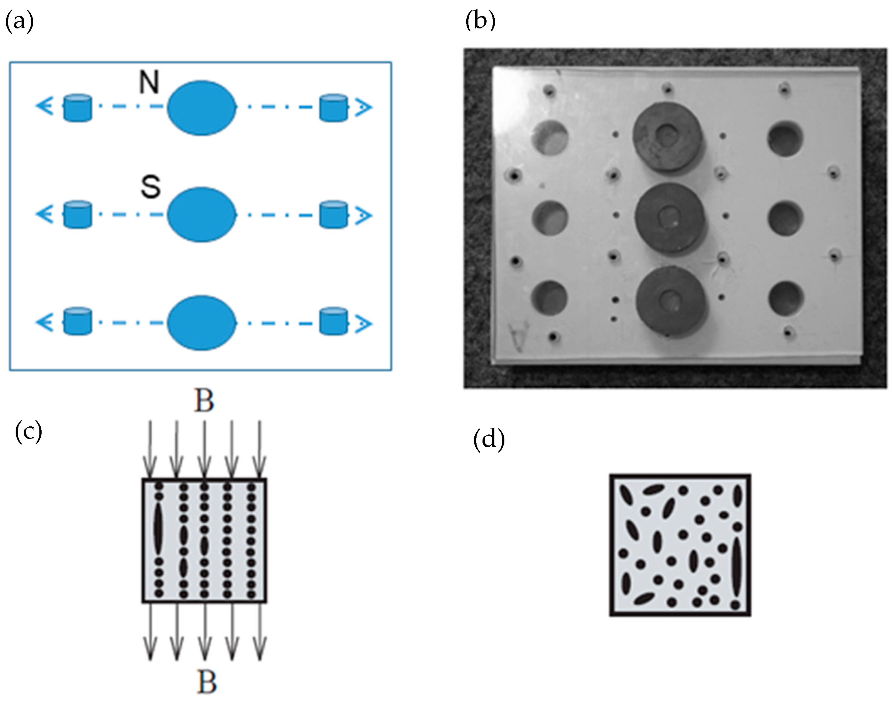
Figure 2.
Schematic representation (a–c) of the MRE composite fabrication with anisotropic filler distribution with the presence of magnetic field and (d) isotropic filler distribution without the presence of magnetic field.
Figure 2.
Schematic representation (a–c) of the MRE composite fabrication with anisotropic filler distribution with the presence of magnetic field and (d) isotropic filler distribution without the presence of magnetic field.

Figure 3.
3D internal image of the elastomer matrices (a,b) and the MRE composites (c,d) with isotropic filler distribution.
Figure 3.
3D internal image of the elastomer matrices (a,b) and the MRE composites (c,d) with isotropic filler distribution.
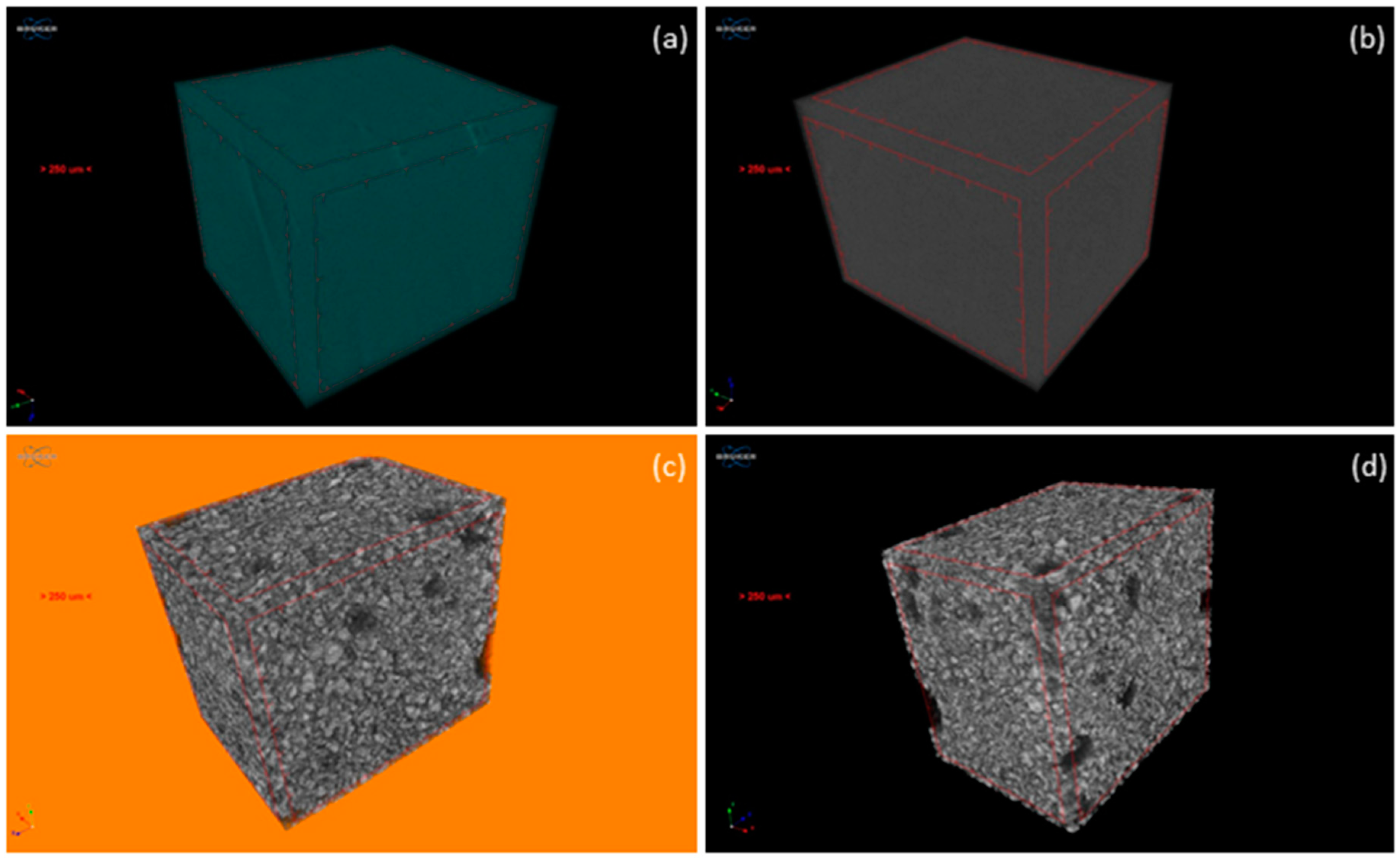
Figure 4.
2D cut view of the MRE composite with (a,b) isotropic filler distribution shows homogenous structure without any porosity (elastomers A and B); (c,d) anisotropic distribution shows more voids due to magnetic field (elastomers A and B).
Figure 4.
2D cut view of the MRE composite with (a,b) isotropic filler distribution shows homogenous structure without any porosity (elastomers A and B); (c,d) anisotropic distribution shows more voids due to magnetic field (elastomers A and B).
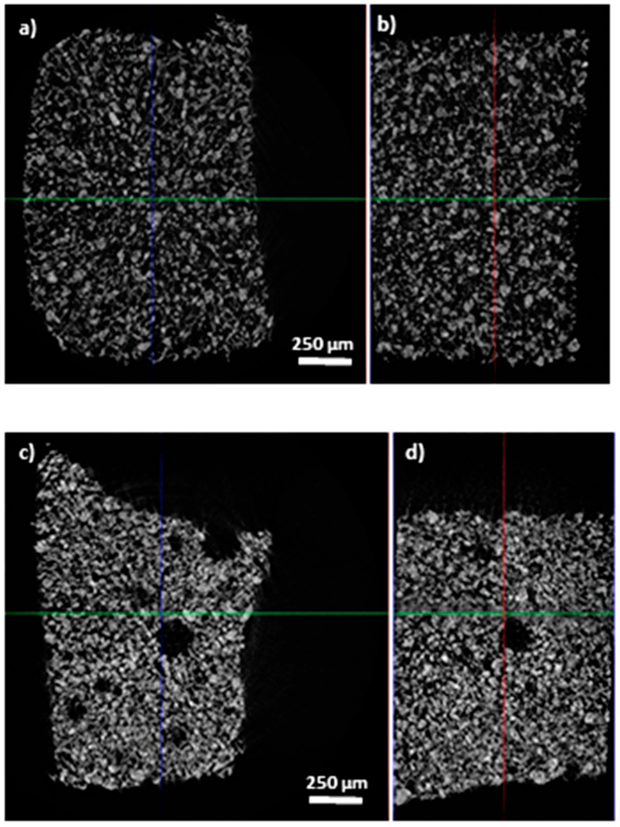
Figure 5.
Scanning electron microscopy (SEM) images of the MRE composites A and B without the presence of a magnetic field (a,b), and prepared in the presence of a magnetic field (c,d).
Figure 5.
Scanning electron microscopy (SEM) images of the MRE composites A and B without the presence of a magnetic field (a,b), and prepared in the presence of a magnetic field (c,d).
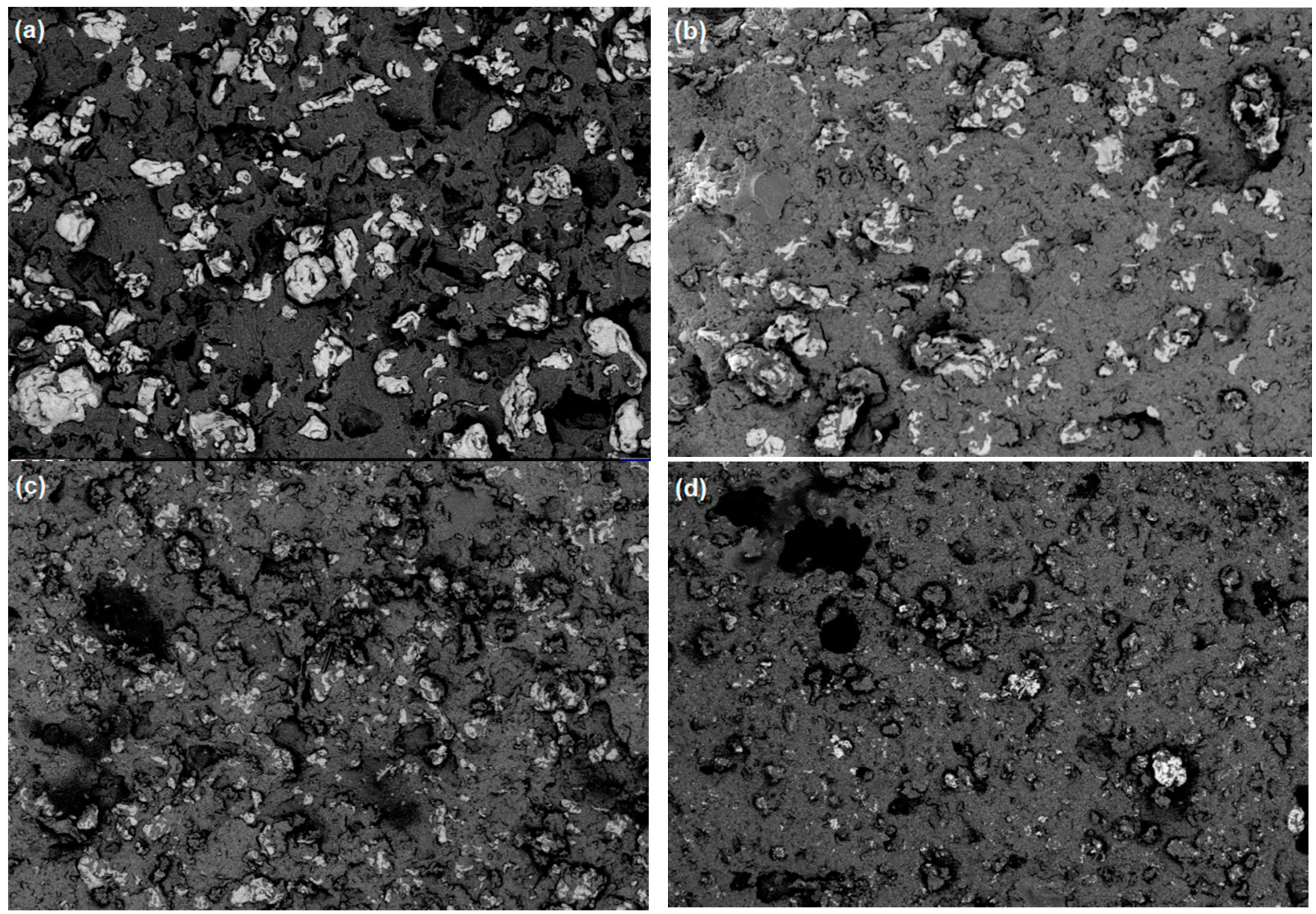
Figure 6.
SEM images of the surface (height = 0 mm) of the composites A (a) and B (b).

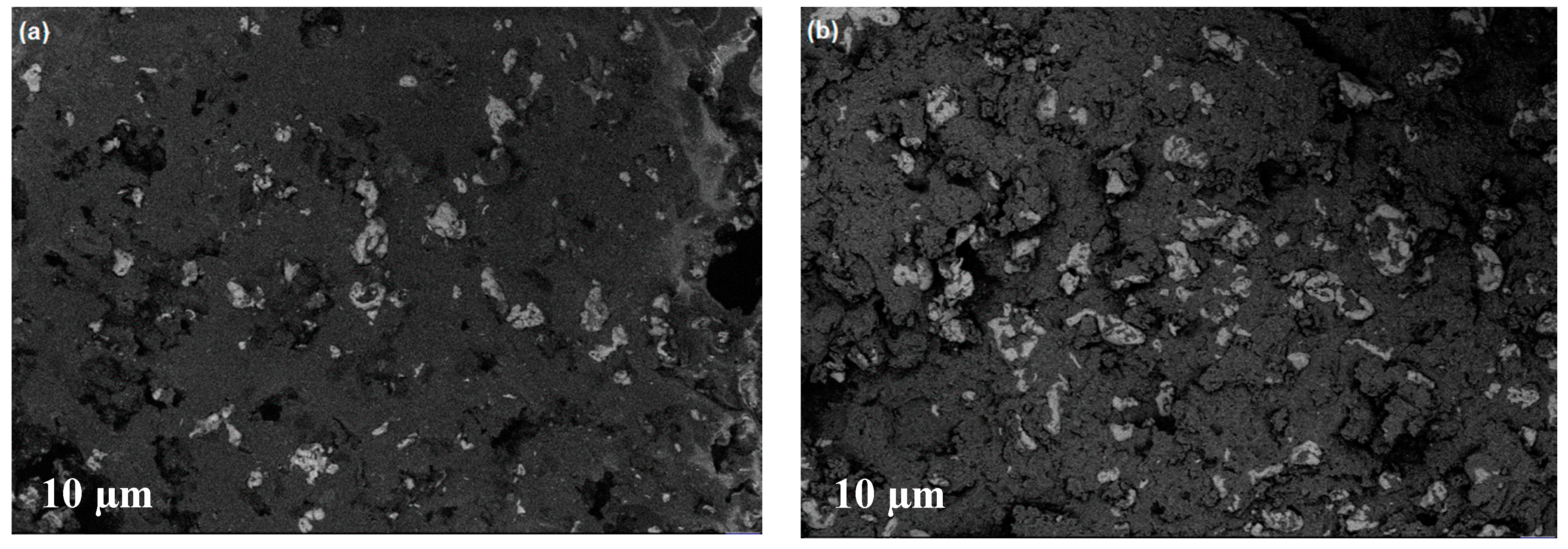
Figure 7.
SEM images of the inner surface (height = 0.8 mm) of the composites A (a) and B (b).

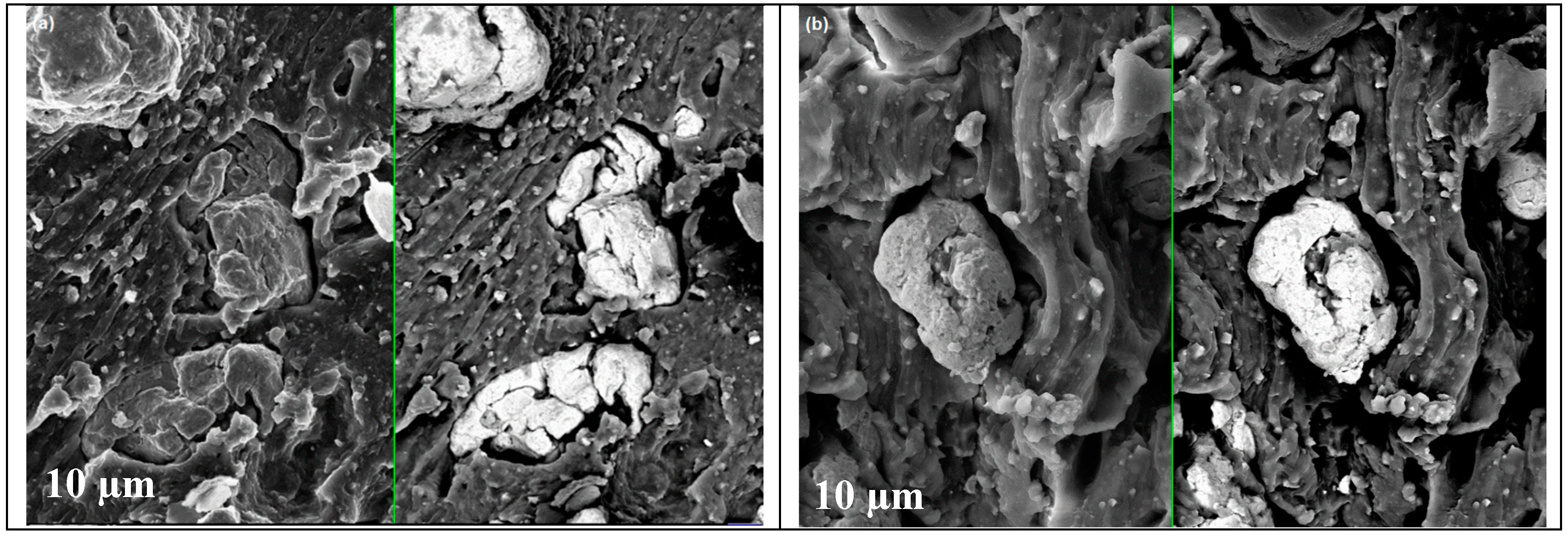
Figure 8.
SEM images showing filler–matrix adhesion for the composites A (a) and B (b).

Figure 9.
Distribution of filler with single and binary behavior as a function of the height of the MRE composite.
Figure 9.
Distribution of filler with single and binary behavior as a function of the height of the MRE composite.

Figure 10.
Iron particle distribution within various heights of the MRE composite from the top to the bottom areas.
Figure 10.
Iron particle distribution within various heights of the MRE composite from the top to the bottom areas.

Figure 11.
Distribution of magnetic induction in the MRE composite.
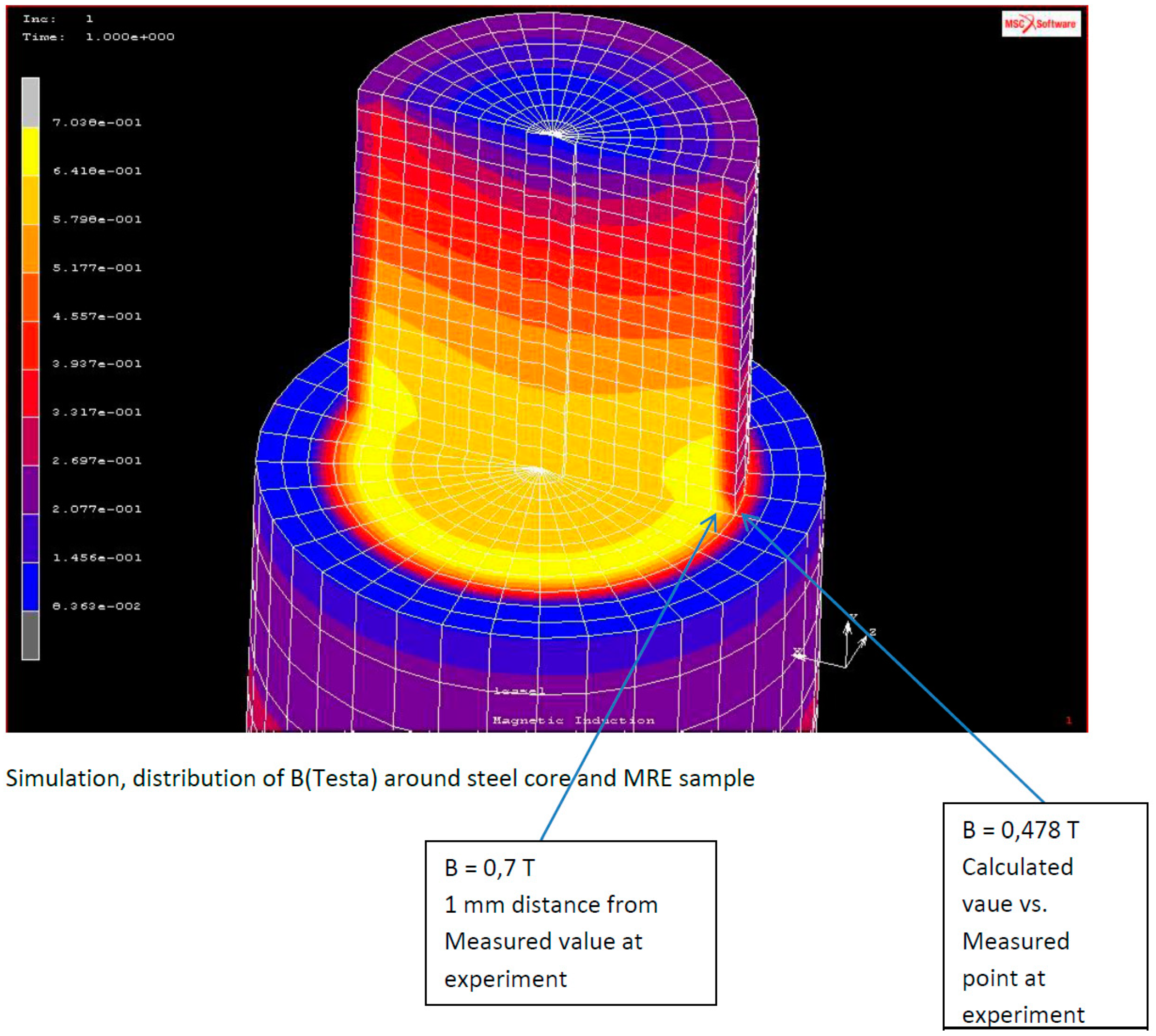
Figure 12.
Magnetic induction distribution around the coil and sample on the top (a), and inside the MRE composite (b).
Figure 12.
Magnetic induction distribution around the coil and sample on the top (a), and inside the MRE composite (b).

Figure 13.
Iron particle distribution before and after the application of the magnetic field.

Table 1.
Composition and polarizable character of the magnetorheological elastomer (MRE) composites.
Table 1.
Composition and polarizable character of the magnetorheological elastomer (MRE) composites.
| Sample | Filler | Matrix | Polarized |
|---|---|---|---|
| A | 0 | N1522 | no |
| A1 | 30 V% | N1522 | no |
| A2 | 30 V% | N1522 | yes |
| B | 0 | ZA22 | no |
| B1 | 30 V% | ZA22 | no |
| B2 | 30 V% | ZA22 | yes |
© 2019 by the authors. Licensee MDPI, Basel, Switzerland. This article is an open access article distributed under the terms and conditions of the Creative Commons Attribution (CC BY) license (http://creativecommons.org/licenses/by/4.0/).
Share and Cite
MDPI and ACS Style
Samal, S.; Škodová, M.; Blanco, I. Effects of Filler Distribution on Magnetorheological Silicon-Based Composites. Materials 2019, 12, 3017. https://doi.org/10.3390/ma12183017
AMA Style
Samal S, Škodová M, Blanco I. Effects of Filler Distribution on Magnetorheological Silicon-Based Composites. Materials. 2019; 12(18):3017. https://doi.org/10.3390/ma12183017
Chicago/Turabian StyleSamal, Sneha, Marcela Škodová, and Ignazio Blanco. 2019. "Effects of Filler Distribution on Magnetorheological Silicon-Based Composites" Materials 12, no. 18: 3017. https://doi.org/10.3390/ma12183017
Note that from the first issue of 2016, this journal uses article numbers instead of page numbers. See further details here.