Studying Grain Boundary Strengthening by Dislocation-Based Strain Gradient Crystal Plasticity Coupled with a Multi-Phase-Field Model


Abstract
:
1. Introduction
2. Model
2.1. The Multi Phase Field Model
2.2. Elasticity
2.3. Plasticity
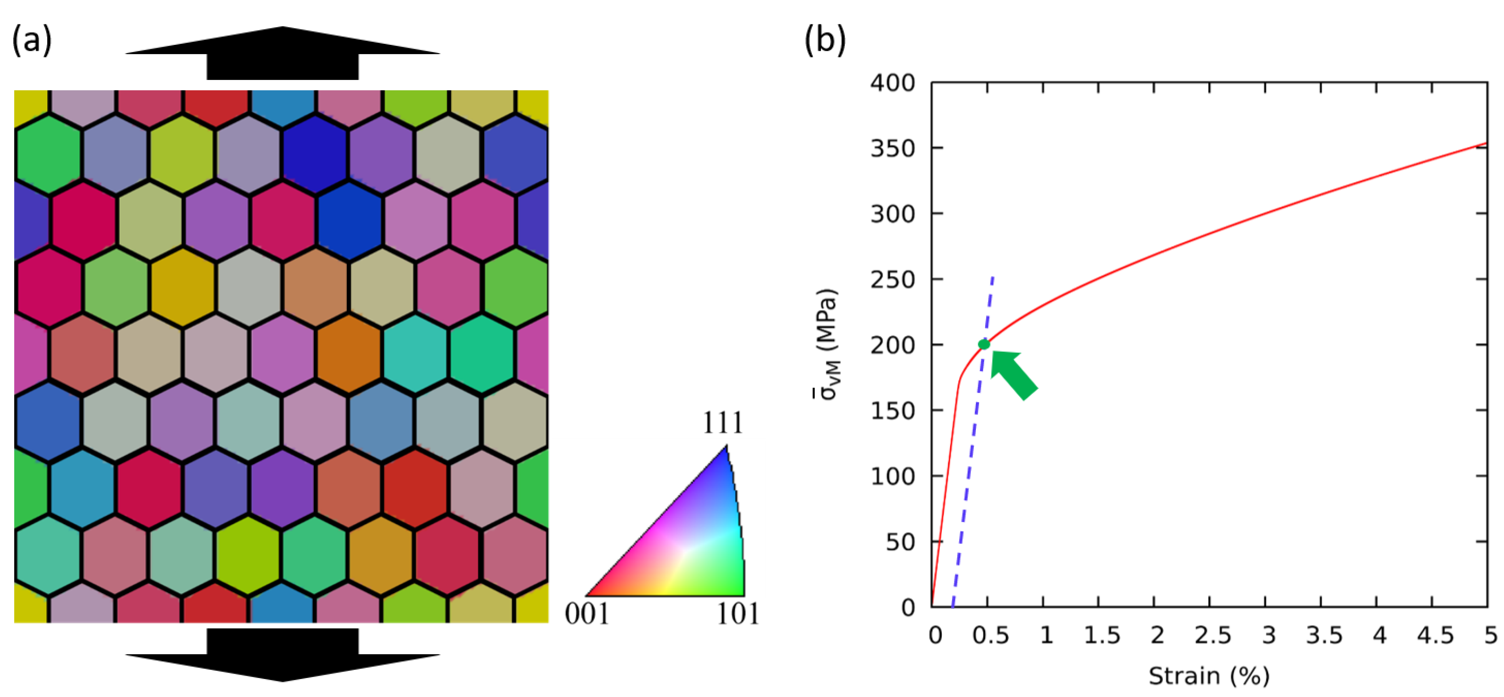
3. Simulation Setup
4. Results and Discussion
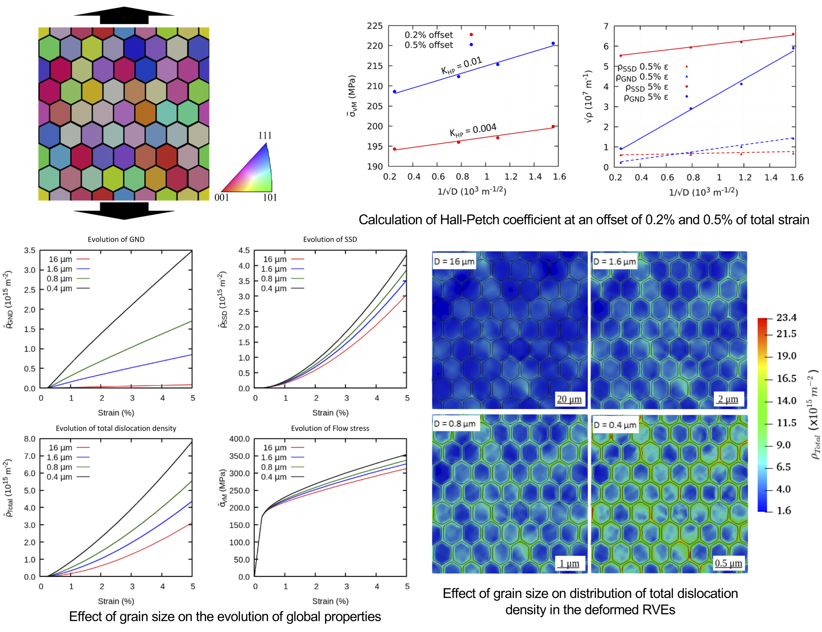
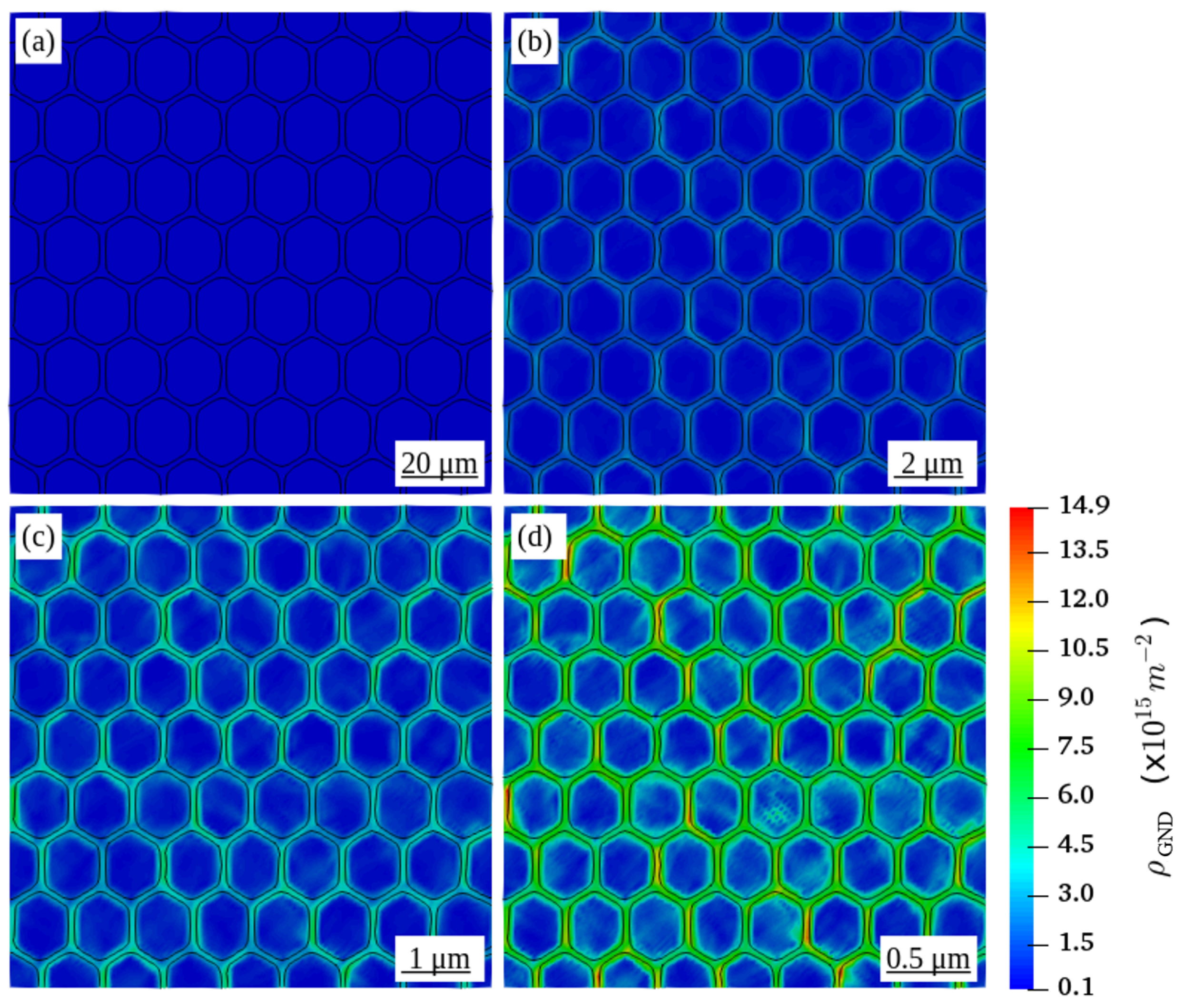
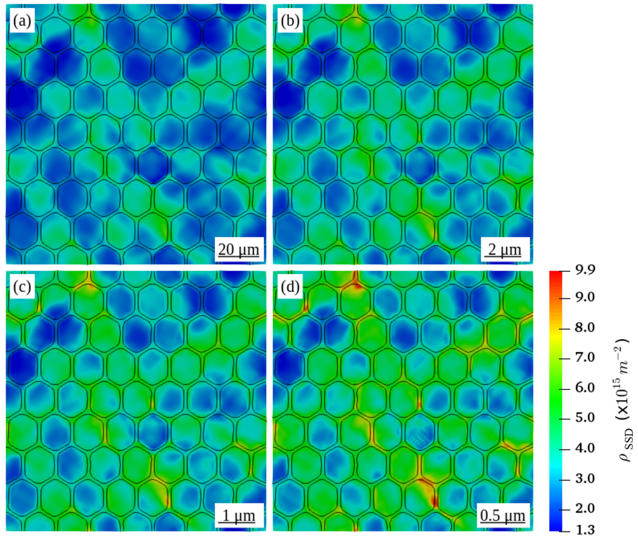
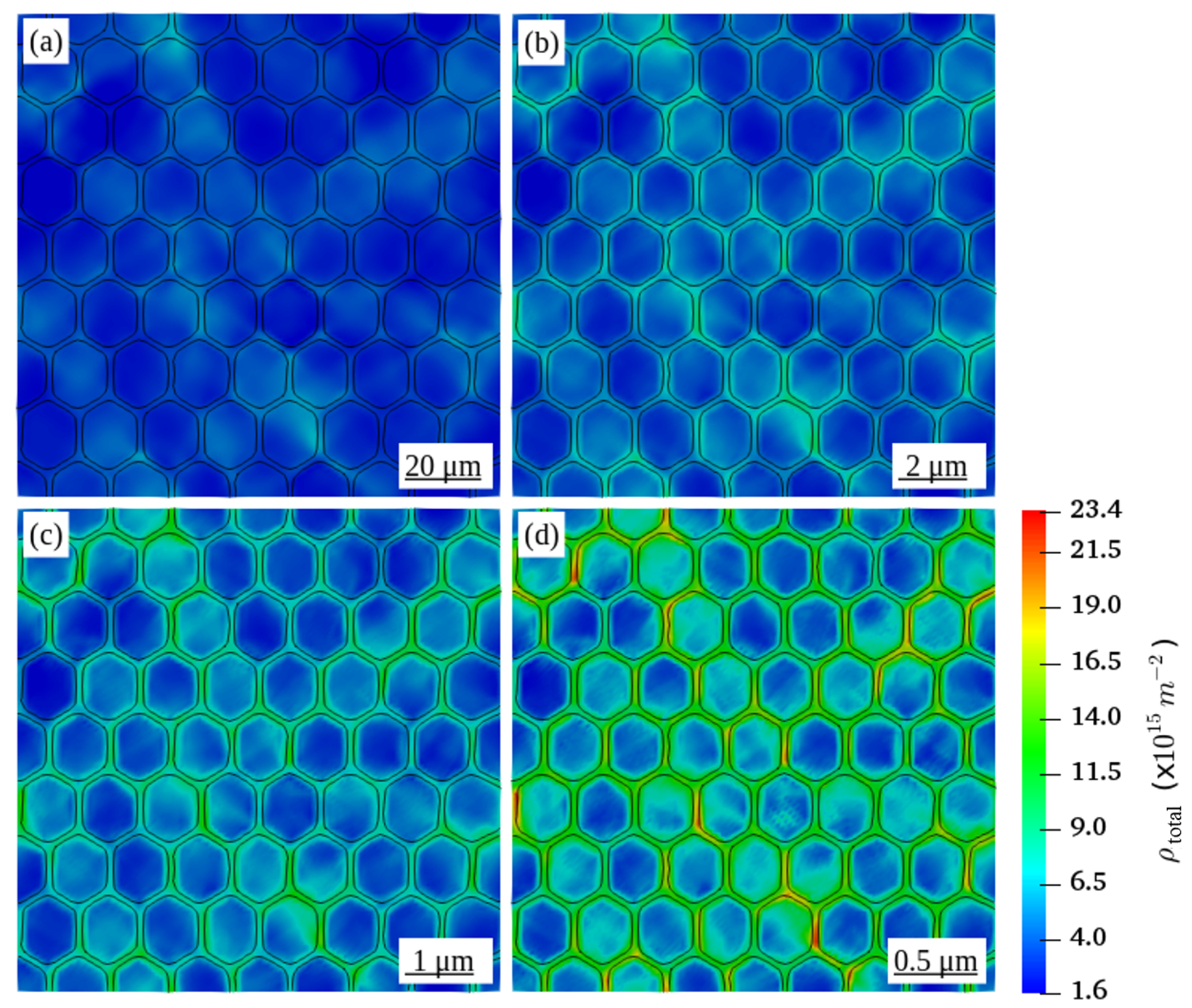
4.1. Effect of the Grain Size on the Distribution of Dislocation Density
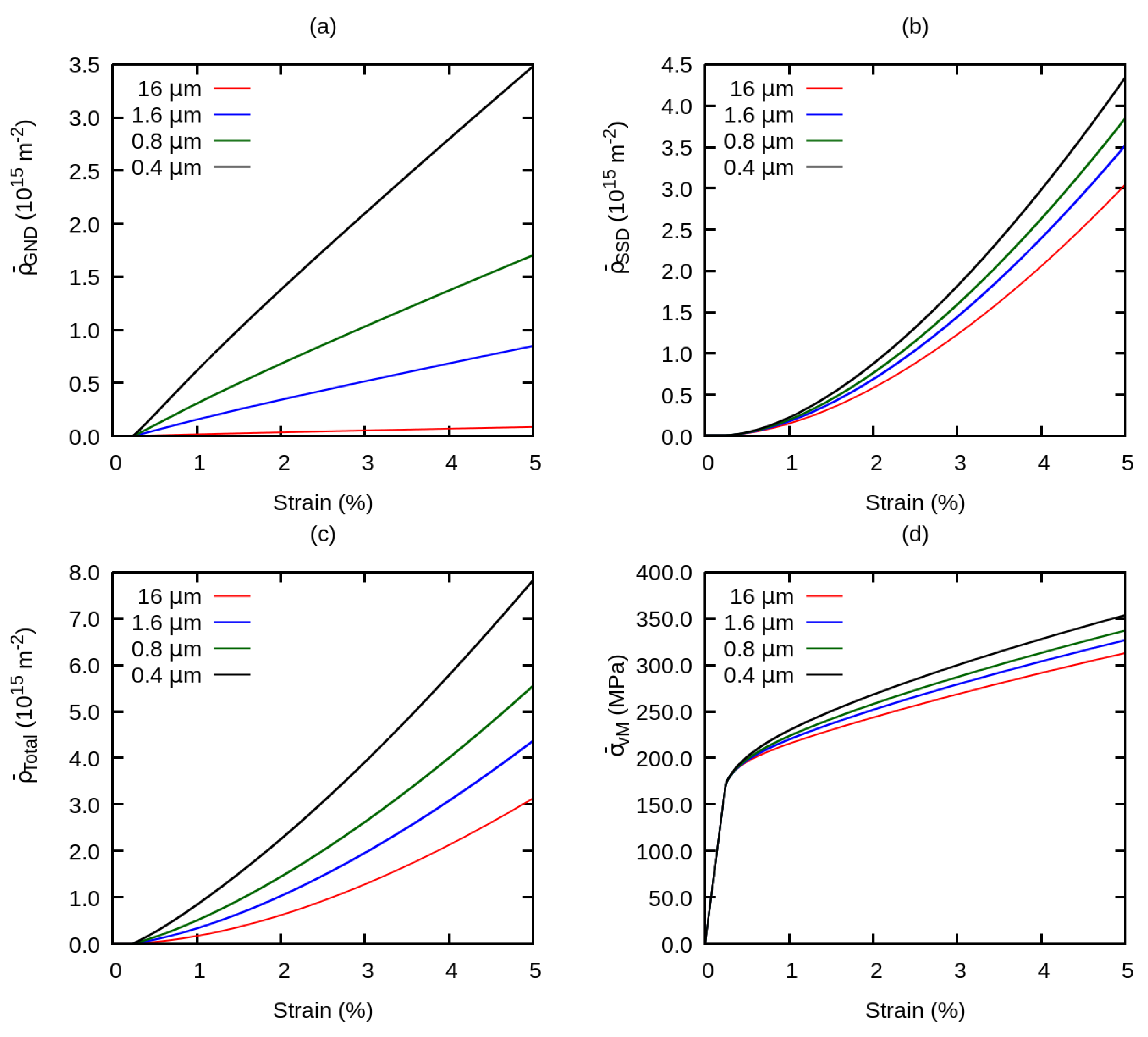
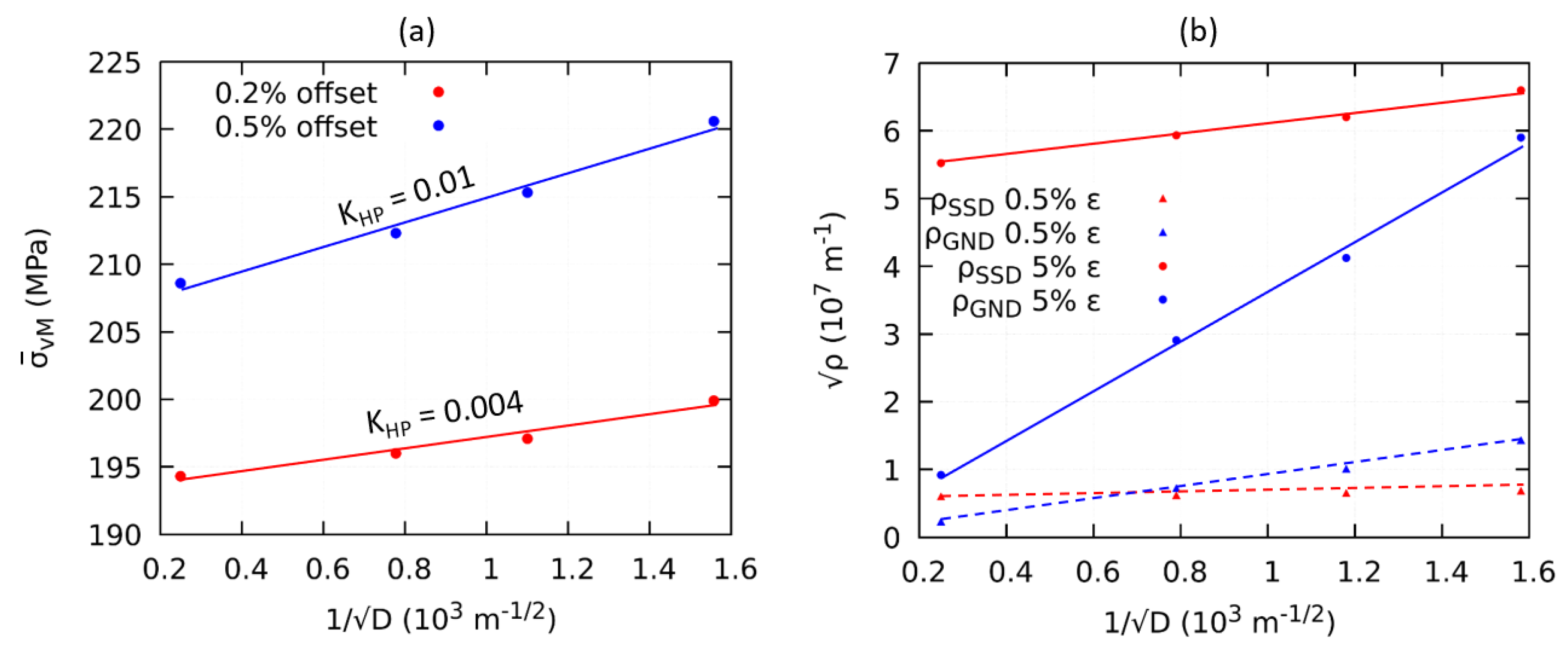
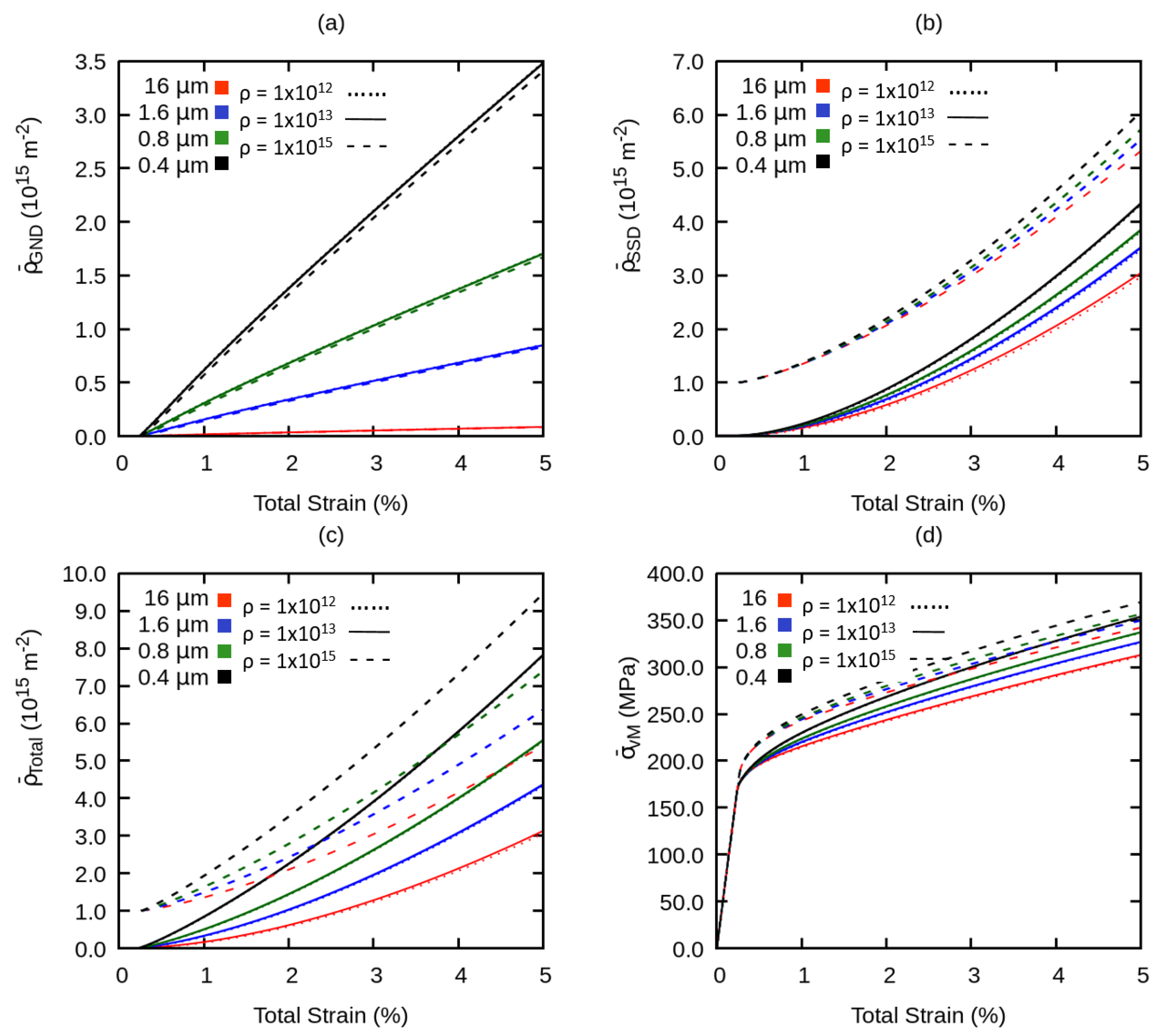
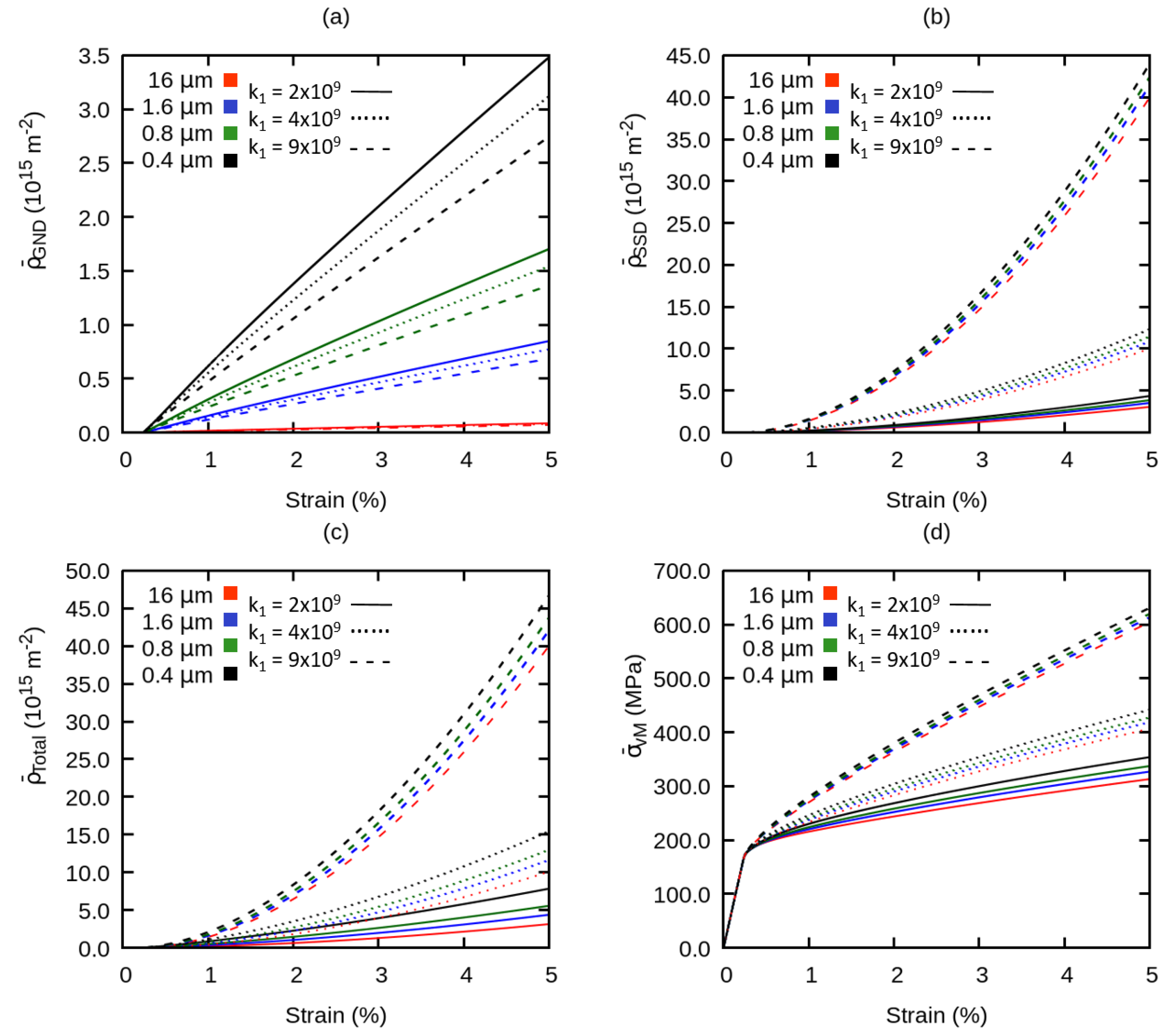
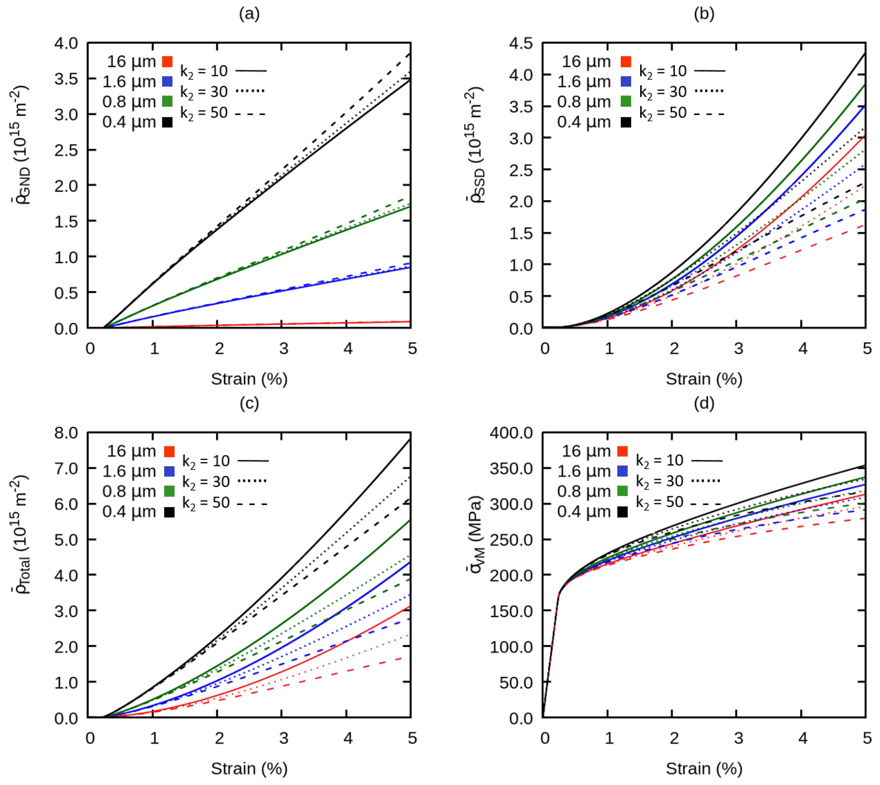
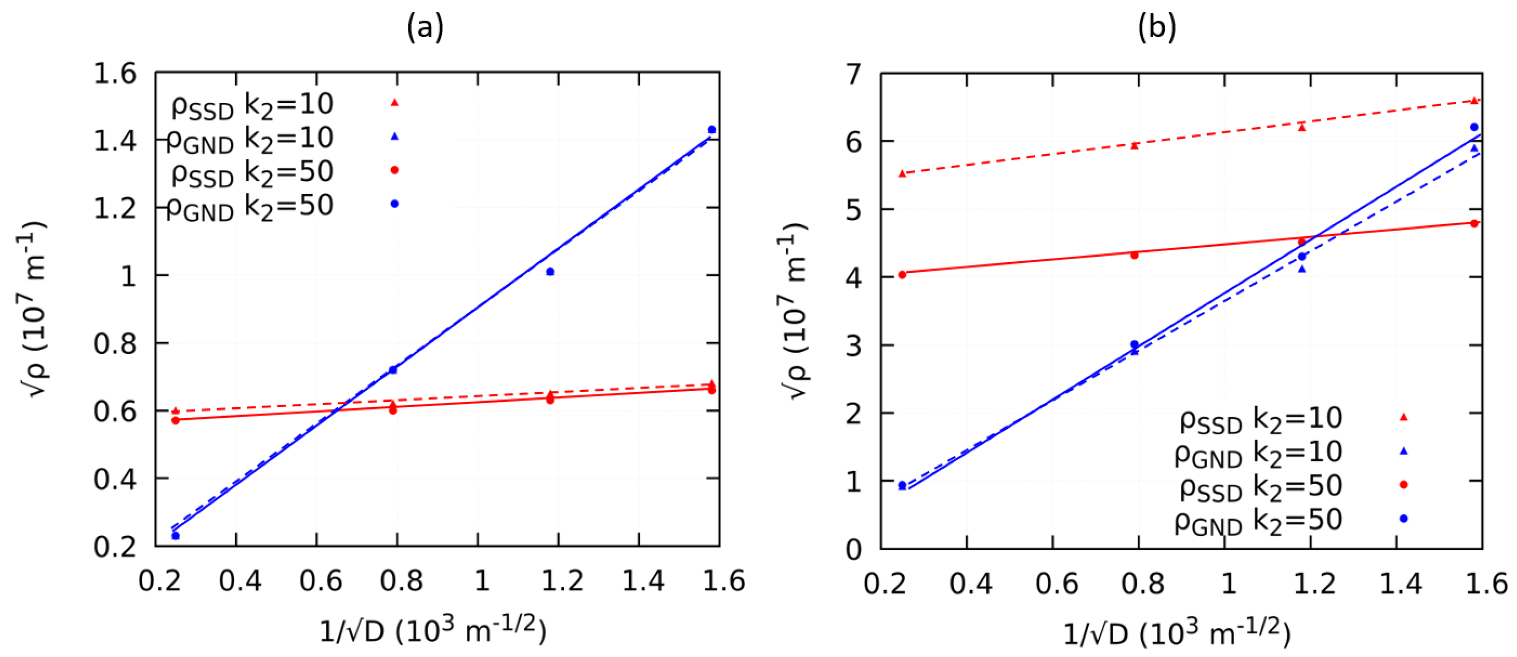
4.2. Averaged Stress and Dislocation Density Under the Influence of Model Parameters
5. Conclusions
- Our work shows that by applying a dislocation-based strain gradient crystal plasticity model, we can capture many aspects of grain boundary strengthening as it is observed in experiments. This conforms to the Hall-Petch model in which the introduction of special properties for grain boundaries is not necessary.
- The model introduced in our work is capable of recapturing the Hall-Petch relation with an exponent of −0.5 for the grain size dependence. Furthermore our model is consistent with the experimental observations of the evolution of the Hall-Petch coefficient with progressing plastic deformation and the initial state of the material with respect to dislocation density.
- The value of the Hall-Petch coefficient predicted by our model is significantly smaller than those observed through experiments and the strain gradient plasticity is unable to explain the grain boundary strengthening at the onset of plastic yielding. This has been discussed in light of the initial state of the material in particular with respect to the initial GND density prior to mechanical testing.
Author Contributions
Funding
Acknowledgments
Conflicts of Interest
Nomenclature
| CP | Crystal plasticity |
| MPF | Multi phase field |
| GND | Geometrically necessary dislocations |
| SSD | Statistically stored dislocations |
| RVE | Representative volume element |
| Resolved shear stress on s slip system | |
| Critical resolved shear stress on s slip system | |
| Dislocation velocity on s slip system | |
| Initial dislocation velocity | |
| Equivalent plastic strain | |
| Shear strain rate | |
| c | Geometrical constant |
| G | Shear modulus |
| s | Arbitrary slip system |
| Domain/system size | |
| Order parameter/phase field parameter | |
| Arbitrary name for a phase phase/grain | |
| F | Total free energy of the system |
| Interfacial free energy | |
| Elastic or mechanical free energy | |
| N | Total number of slip systems or phases |
| Interfacial width | |
| Density of dislocations | |
| Density of SSD | |
| Density of GND | |
| k | SSD storage parameter |
| k | SSD annihilation parameter |
| m | Strain rate sensitivity parameter |
| Interfacial energy between arbitrary phase or grain and | |
| Symmetric part of Schmidt tensor on slip system s | |
| von Mises equivalent stress | |
| Total strain tensor | |
| Elastic strain tensor | |
| Eigen strain tensor | |
| Plastic strain tensor | |
| Stress tensor | |
| Nye’s dislocation tensor | |
| Stiffness tensor | |
| Deformation gradient | |
| Burgers vector | |
| Slip direction vector | |
| Slip plane tangent vector | |
| Slip plane normal vector |
References
- Uchic, M.D.; Shade, P.A.; Dimiduk, D.M. Plasticity of micrometer-scale single crystals in compression. Annu. Rev. Mater. Res. 2009, 39, 361–386. [Google Scholar] [CrossRef]
- Greer, J.R.; Hosson, J.T.D. Plasticity in small-sized metallic systems: Intrinsic versus extrinsic size effect. Prog. Mater. Sci. 2011, 65, 654–724. [Google Scholar] [CrossRef]
- Hall, E. The deformation and ageing of mild steel: III discussion of results. Proc. Phys. Soc. Sect. B 1951, 64, 747. [Google Scholar] [CrossRef]
- Petch, N.J. The cleavage strength of polycrystals. J. Iron Steel Inst. 1953, 174, 25–28. [Google Scholar]
- Hansen, N. The effect of grain size and strain on the tensile flow stress of Aluminum at room temperature. Acta Metall. 1977, 25, 863–869. [Google Scholar] [CrossRef]
- Evers, L.; Parks, D.; Brekelmans, W.; Geers, M. Crystal plasticity model with enhanced hardening by geometrically necessary dislocation accumulation. J. Mech. Phys. Solids 2002, 50, 2403–2424. [Google Scholar] [CrossRef]
- Hasegawa, T.; Sakurai, Y.; Okazaki, K. Grain size effect on thermal recovery during high temperature deformation of aluminum tested at constant true strain rates. Mater. Sci. Eng. A 2003, 346, 34–41. [Google Scholar] [CrossRef]
- Cheong, K.; Busso, E.; Arsenlis, A. A study of microstructural length scale effects on the behaviour of FCC polycrystals using strain gradient concepts. Int. J. Plast. 2005, 21, 1797–1814. [Google Scholar] [CrossRef] [Green Version]
- Thangaraju, S.; Heilmaier, M.; Murty, B.S.; Vadlamani, S.S. On the estimation of true Hall–Petch constants and their role on the superposition law exponent in Al alloys. Adv. Eng. Mater. 2012, 14, 892–897. [Google Scholar] [CrossRef]
- Ghassemali, E.; Tan, M.J.; Beng Wah, C.; Lim, S.; Jarfors, A.E. Effect of cold-work on the Hall-Petch breakdown in copper based micro-components. Mech. Mater. 2015, 80, 124–135. [Google Scholar] [CrossRef]
- Roters, F.; Eisenlohr, P.; Hantcherli, L.; Tjahjanto, D.; Bieler, T.; Raabe, D. Overview of constitutive laws, kinematics, homogenization and multiscale methods in crystal plasticity finite-element modeling: Theory, experiments, applications. Acta Mater. 2010, 58, 1152–1211. [Google Scholar] [CrossRef]
- Brown, L.M. Constant intermittent flow of dislocations: central problems in plasticity. Mater. Sci. Technol. 2012, 28, 1209–1232. [Google Scholar] [CrossRef]
- Kubin, L.P.; Mortensen, A. Geometrically necessary dislocations and strain-gradient plasticity: A few critical issues. Scr. Mater. 2003, 48, 119–125. [Google Scholar] [CrossRef]
- Firstov, S.A.; Rogul, T.G.; Shut, O.A. Generalized grain-size dependence of flow stress. Russ. Metall. (Metally) 2016, 2016, 257–265. [Google Scholar] [CrossRef]
- Gu, R.; Ngan, A.H.W. Effects of pre-straining and coating on plastic deformation of Aluminum micropillars. Acta Mater. 2012, 60, 6102–6111. [Google Scholar] [CrossRef]
- Huang, Y.; Qu, S.; Hwang, K.C.; Li, M.; Gao, H. A conventional theory of mechanism-based strain gradient plasticity. Int. J. Plast. 2004, 20, 753–782. [Google Scholar] [CrossRef]
- Fleck, N.A.; Hutchinson, J.W. Strain gradient plasticity. Adv. Appl. Mech. 1997, 33, 295–361. [Google Scholar]
- Lyu, H.; Hamid, M.; Ruimi, A.; Zbib, H.M. Stress/strain gradient plasticity model for size effects in heterogeneous nano-microstructures. Int. J. Plast. 2017, 97, 46–63. [Google Scholar] [CrossRef]
- Ma, A.; Hartmaier, A. On the influence of isotropic and kinematic hardening caused by strain gradients on the deformation behaviour of polycrystals. Philos. Mag. 2013, 94, 125–140. [Google Scholar] [CrossRef]
- Ashby, M.F. The deformation of plastically non-homogeneous materials. Philos. Mag. J. Theor. Exp. Appl. Phys. 1970, 21, 399–424. [Google Scholar] [CrossRef]
- Armstrong, R.; Codd, I.; Douthwaite, R.M.; Petch, N.J. The plastic deformation of polycrystalline aggregates. Philos. Mag. J. Theor. Exp. Appl. Phys. 1962, 7, 45–58. [Google Scholar] [CrossRef]
- Mecking, H.; Kocks, U.F. Kinetics of flow and strain and strain-hardening. Acta Metall. 1981, 29, 1865–1875. [Google Scholar] [CrossRef]
- Nye, J.F. Some geometrical relations in dislocated crystals. Acta Metall. 1953, 1, 153–162. [Google Scholar] [CrossRef]
- Suresh, S.; Li, J. Deformation of the ultra-strong. Nature 2008, 456, 716–717. [Google Scholar] [CrossRef] [PubMed]
- Boettinger, W.J.; Warren, J.A.; Beckermann, C.; Karma, A. Phase-Field Simulation of Solidification. Annu. Rev. Mater. Res. 2002, 32, 163–194. [Google Scholar] [CrossRef]
- Wang, Y.U.; Jin, Y.M.; Khachaturyan, A.G. Phase field microelasticity theory and modeling of elastically and structurally inhomogeneous solid. J. Appl. Phys. 2002, 92, 1351. [Google Scholar] [CrossRef]
- Borukhovich, E.; Engels, P.S.; Böhlke, T.; Shchyglo, O.; Steinbach, I. Large strain elasto-plasticity for diffuse interface models. Model. Simul. Mater. Sci. Eng. 2014, 22, 034008. [Google Scholar] [CrossRef]
- Engels, P.S. A Multiphasefield Simulation Approach Incorprating Finite, Elastoplastic Deformations. Ph.D. Thesis, ICAMS, Ruhr Universität Bochum, Bochum, Germany, 2016. [Google Scholar]
- Koslowski, M.; Cuitiño, A.M.; Ortiz, M. A phase-field theory of dislocation dynamics, strain hardening and hysteresis in ductile single crystals. J. Mech. Phys. Solids 2002, 50, 2597–2635. [Google Scholar] [CrossRef] [Green Version]
- Shen, C.; Wang, Y. Phase field model of dislocation networks. Acta Mater. 2003, 21, 2595–2610. [Google Scholar] [CrossRef]
- Rodney, D.; Bouar, Y.L.; Finel, A. Phase field methods and dislocations. Acta Mater. 2003, 51, 17–30. [Google Scholar] [CrossRef] [Green Version]
- Hu, S.Y.; Li, Y.L.; Zheng, Y.X.; Chen, L.Q. Effect of solutes on dislocation motion—A phase-field simulation. Int. J. Plast. 2004, 20, 403–425. [Google Scholar] [CrossRef]
- Zhou, N.; Shen, C.; Mills, M.; Wang, Y. Phase field modeling of channel dislocation activity and γ’ rafting in single crystal Ni–Al. Acta Mater. 2007, 55, 5369–5381. [Google Scholar] [CrossRef]
- Hunter, A.; Beyerlein, I.J.; Germann, T.C.; Koslowski, M. Influence of the stacking fault energy surface on partial dislocations in fcc metals with a three-dimensional phase field dislocations dynamics model. Phys. Rev. B 2011, 84, 144108. [Google Scholar] [CrossRef]
- Ruffini, A.; Bouar, Y.L.; Finel, A. Three-dimensional phase-field model of dislocations for a heterogeneous face-centered cubic crystal. J. Mech. Phys. Solids 2017, 105, 95–115. [Google Scholar] [CrossRef]
- Zheng, S.; Zheng, D.; Ni, Y.; He, L. Improved phase field model of dislocation intersections. NPJ Comput. Mater. 2018, 4, 20. [Google Scholar] [CrossRef]
- Aldakheel, F. Mechanics of Nonlocal Dissipative Solids: Gradient Plasticity And Phase Field Modeling of Ductile Fracture. Ph.D. Thesis, Institut für Mechanik (Bauwesen), Lehrstuhl I, Universität Stuttgart, Stuttgart, Germany, 2016. [Google Scholar]
- Steinbach, I.; Apel, M. Multi phase field model for solid state transformation with elastic strain. Phys. D Nonlinear Phenomena 2006, 217, 153–160. [Google Scholar] [CrossRef]
- Borukhovich, E.; Engels, P.S.; Mosler, J.; Shchyglo, O.; Steinbach, I. Large deformation framework for phase-field simulations at the mesoscale. Comput. Mater. Sci. 2015, 108, 367–373. [Google Scholar] [CrossRef]
- Engels, P.; Ma, A.; Hartmaier, A. Simulation of the evolution of dislocation densities during nanoindentation. Int. J. Plast. 2012, 38, 159–169. [Google Scholar] [CrossRef]
- Interdisciplinary Centre for Advanced Materials Simulation (ICAMS); Ruhr Universität Bochum, Bochum, Germany. OpenPhase—The Open Source Phase-Field Simulation Package. Available online: https://www.openphase.de (accessed on 8 September 2019).
- Ogden, R.W. Non-Linear Elastic Deformations; Dover Publications: Dover, UK, 1984. [Google Scholar]
- Hertzberg, R.W.; Vinci, R.P.; Hertzberg, J.L. Deformation and Fracture Mechanics of Engineering Materials; John Wiley & Sons: New York, NY, USA, 1976. [Google Scholar]
- Rezvanian, O.; Zikry, M.; Rajendran, A. Statistically stored, geometrically necessary and grain boundary dislocation densities: Microstructural representation and modelling. Proc. R. Soc. A 2007, 463, 2833–2853. [Google Scholar] [CrossRef]
- Rycroft, C.H. VORO++: A three-dimensional Voronoi cell library in C++. Chaos Interdiscip. J. Nonlinear Sci. 2009, 19, 041111. [Google Scholar] [CrossRef] [Green Version]
- Horn, R.A.; Johnson, C.R. Norms for Vectors and Matrices; Cambridge University Press: Cambridge, UK, 1990. [Google Scholar]
- Huang, Y.; Gao, H.; Nix, W.; Hutchinson, J. Mechanism-based strain gradient plasticity-II. Analysis. J. Mech. Phys. Solids 2000, 48, 99–128. [Google Scholar] [CrossRef]
- El-Awady, J.A. Unravelling the physics of size-dependent dislocation-mediated plasticity. Nat. Commun. 2015, 6. [Google Scholar] [CrossRef] [PubMed]
- Counts, W.A.; Braginsky, M.V.; Battaile, C.C.; Holm, E.A. Predicting the Hall-Petch effect in fcc metals using non-local crystal plasticity. Int. J. Plast. 2008, 24, 1243–1263. [Google Scholar] [CrossRef]
- Aldazabal, J.; Sevillano, J. Hall–Petch behaviour induced by plastic strain gradients. Mater. Sci. Eng. A 2004, 365, 186–190. [Google Scholar] [CrossRef]


| Slip System | Plane Normal | Slip Direction | Line Direction |
|---|---|---|---|
| s | n | d | l |
| 1 | [111] | [10] | [11] |
| 2 | [111] | [10] | [2] |
| 3 | [111] | [01] | [11] |
| 4 | [11] | [0] | [12] |
| 5 | [11] | [101] | [12] |
| 6 | [11] | [01] | [211] |
| 7 | [11] | [110] | [12] |
| 8 | [11] | [10] | [121] |
| 9 | [11] | [0] | [21] |
| 10 | [1] | [10] | [] |
| 11 | [11] | [101] | [1] |
| 12 | [11] | [011] | [21] |
| Parameters | Symbol | Value | Unit | Ref. |
|---|---|---|---|---|
| Anisotropic elastic constant | C | 108.2 | GPa | [43] |
| Anisotropic elastic constant | C | 61.3 | GPa | [43] |
| Shear Modulus | C = G | 28.5 | GPa | [43] |
| Strain rate sensitivity | m | 0.025 | - | |
| Lattice friction stress | 80 | MPa | ||
| SSD storage parameter | k | 2 × | - | [40] |
| SSD annihilation parameter | k | 10 | - | [40] |
| Initial total dislocation density | 1 × | m | ||
| Geometrical factor for flow stress | c | 0.3 | - | [20,44] |
| Referential dislocation velocity | 1 × | ms | ||
| Interfacial energy | 0.24 | Jm | [28] | |
| Spacediscretization | x | 0.1 | m | |
| Timediscretization | t | 1 | s | |
| Interfacial width | 4.5 | x | ||
| Domain size | 128 × 128 | x | ||
| Length of Burger’s vector | b | 0.286 | nm |
© 2019 by the authors. Licensee MDPI, Basel, Switzerland. This article is an open access article distributed under the terms and conditions of the Creative Commons Attribution (CC BY) license (http://creativecommons.org/licenses/by/4.0/).
Share and Cite
Amin, W.; Ali, M.A.; Vajragupta, N.; Hartmaier, A. Studying Grain Boundary Strengthening by Dislocation-Based Strain Gradient Crystal Plasticity Coupled with a Multi-Phase-Field Model. Materials 2019, 12, 2977. https://doi.org/10.3390/ma12182977
Amin W, Ali MA, Vajragupta N, Hartmaier A. Studying Grain Boundary Strengthening by Dislocation-Based Strain Gradient Crystal Plasticity Coupled with a Multi-Phase-Field Model. Materials. 2019; 12(18):2977. https://doi.org/10.3390/ma12182977
Chicago/Turabian StyleAmin, Waseem, Muhammad Adil Ali, Napat Vajragupta, and Alexander Hartmaier. 2019. "Studying Grain Boundary Strengthening by Dislocation-Based Strain Gradient Crystal Plasticity Coupled with a Multi-Phase-Field Model" Materials 12, no. 18: 2977. https://doi.org/10.3390/ma12182977