Unified First Order Inertial Element Based Model of Magnetostrictive Hysteresis and Lift-Off Phenomenon


Warsaw University of Technology, Institute of Metrology and Biomedical Engineering, Warsaw 02-525, Poland
Materials 2019, 12(10), 1689; https://doi.org/10.3390/ma12101689
Submission received: 4 May 2019
/
Revised: 19 May 2019
/
Accepted: 22 May 2019
/
Published: 24 May 2019
(This article belongs to the Collection Magnetoelastic Materials)
Abstract
:The present paper presents a new model of magnetostrictive hysteresis loop. A unified approach of both the hysteresis of λ(B) relation, as well as the lift-off phenomenon is proposed, which are explained together on the base of the response of the first order inertial element. Considering previously presented reports, the Maxwell–Boltzmann distribution based model of magnetostrictive characteristics with local maxima, enables modeling magnetostrictive loops. The model was validated on the results of measurements of magnetostrictive hysteresis loops of Mn0.70Zn0.24Fe2.06O4 ferrite for power applications. Good agreement was confirmed for major magnetostrictive loop, especially for smaller values of flux density. As a result, the proposed model may be used for modeling the magnetostrictive response of inductive components of electrical machines, power conversion devices or magnetostrictive actuators.
1. Introduction
The magnetostriction phenomenon, observed for the first time by Joule in 1847 [1], is connected with changes of linear dimensions of the sample during the magnetization process. In spite of over hundred years of research on magnetostriction, it seems to still be one of the most mysterious macroscopic effects in the area of solid-state physics.
Magnetostriction is one of the sets of thermodynamically connected magneto-mechanical effects [2] summarized in Table 1.
Considering the fact, that the thermodynamically inverse effect to magnetostriction is the magnetoelastic Villari effect [16,17], it should be assumed, that magnetostriction is rather connected with changes of the magnetic state of material (described by its magnetization M or flux density B), than the value of external magnetizing field H. As a result, the magnetostriction λ compared to the magnetization M (or flux density B) dependence is the key for understanding the quantitative description of the magnetostrictive phenomenon.
Both the magnetostrictive hysteresis and lift-off phenomenon are very important from the point of view of modeling the magnetostrictive characteristics. These phenomena determine the accuracy of magnetostrictive positioning devices as well as being important for the development of the sensors utilizing magnetostrictive effects. For this reason, both are in the area of interests of engineers and scientists involved in research of soft magnetic materials.
The most efficient way to model the hysteresis loop is to model the anhysteretic curve first and later add the hysteresis and lift-off phenomenon description. The lift-off phenomenon is connected with the fact that the value of magnetostriction λ never returns to its initial value observed after demagnetization. The approach with a separate description of anhysteretic dependence and hysteresis description was taken in the Jiles-Atherton model of magnetic hysteresis loop [18]. Moreover, the magnetostrictive anhysteretic λ(B) dependence was presented previously for both monotonous curves [3,19], as well as for the curve with local maximum [20]. On the other hand, the hysteresis and the lift-off effect in the magnetostrictive λ(B) dependence was described only by phenomenological dependences [21]. Such dependences represent quite well the shape of λ(B), however, they don’t create the possibility of physical explanation of hysteresis phenomenon.
This paper presents a new approach to the modeling the both magnetostrictive λ(B) hysteresis and the lift-off phenomenon. With the use of the first order inertial element, both the hysteresis of magnetostriction and lift-off phenomenon can be modeled together. Such approach seems to be judged from the physical point of view due to the fact that the origins of these both effects seem to be similar. As a result, the proposed model enables deeper understanding of the physical mechanisms behind the magnetostriction. Moreover, it can be used for the development of magnetostrictive effect-based sensors and actuators, utilized in the industry [22] and medicine [23]. To sum up, the main goal of the paper is to propose the unified model of both magnetostrictive hysteresis and lift-off phenomenon, which can be useful for development of sensors and actuators control systems (e.g., precise micropositioning systems) as well as optimization of the structure of such devices.
2. The Method of Measurements of Magnetostriction and Magnetic Hysteresis Loop is Soft Ferrites
During the investigation, the frame-shaped sample [4] made of Mn0.70Zn0.24Fe2.06O4 ferrite for power applications was used. The sample had dimensions of 70 × 22 × 15 mm. The magnetizing winding had 25 turns, whereas flux density B sensing winding had 50 turns. Measurements were carried out in room temperature with the magnetizing field frequency of 1 Hz.
Measurements were carried out in the quasi-static mode. Due to the high resistivity of ferrites, eddy currents in the core are strongly limited. As a result, 1 Hz is suitable from the point of view of observations of both the magnetostrictive hysteresis and lift-off without the risk of time drift in the measurements of flux density B. The frame-shaped sample with a strain gauge is presented in Figure 1a, whereas the schematic block diagram of the experimental setup is presented in Figure 1b. The proposed, computer controlled measurement stand enabled simultaneous measurements of magnetostriction λ, flux density B and magnetizing field H.
In the proposed measuring system, the magnetostriction is measured by the semiconductor strain gauge method [6]. For the measurements, AP120-6-12 semiconductor strain gauges (VTS, Zlin, Czech Republic) were used in connection with the MT-12 bridge (Meratronic, Warsaw, Poland). Flux density B is measured by the fluxmeter type 480 (Lakeshore, Carson, CA, USA), whereas the magnetizing field H is calculated from the electric current in magnetizing winding measured on the 1 Ω standard resistor.
Figure 2 presents the results of measurements of magnetizing field H, flux density B and magnetizing field H during the single measurement cycle.
3. Principles of Modeling the Anhysteretic Magnetostrictive Hysteresis Curve
Recently developed models of the anhysteretic magnetostrictive hysteresis curve utilized second [21] and fourth [24] order polynomials. The more sophisticated models are based on the differential equations considering both magnetostriction λmov(B) caused the domain wall movement and magnetostriction λrot(B) connected with the domain magnetization rotation. As a result, the differential equation describing anhysteretic λanhyst(B) dependence is given by the following differential equations [20]:
where a1 and a2 are parameters describing the slopes of the anhysteretic curve [20]. The initial condition λanhyst(B) = 0 for B = 0.
Function W(B) determining the change of magnetization mechanism from the domain wall movement to the domain magnetization rotation is proposed in accordance to the Maxwell–Boltzmann statistical distribution given by the following equation [25]:
where erf() is the error function in to the Maxwell–Boltzmann statistical distribution [25]. Parameters Bswitch and k determines the change in magnetization mechanism from the domain wall to the domain magnetization rotation. The Maxwell–Boltzmann distribution was chosen due to the fact, that it is especially useful for the description of transition between different states in population, such as the transition between the magnetization mechanisms based on the domain wall movement and domain magnetization rotation in the population of domains.
Figure 4 presents the results of fitting the magnetostrictive anhysteretic curve λanhyst(B) stated by Equations (1)–(4) into the results of experimental measurements. The parameter identification was carried out on the basis of the differential evolution algorithm with the target function F equal to the sum of the squared differences between the results of measurements and modeling [26].
4. Proposed, First Order Inertial Element Based Model of Magnetostrictive Hysteresis and Lift-Off Phenomenon
Inertial elements are the most common elements of linear automation control theory. The most common example of the first order inertial element is the resistor-capacitor circuit [27]. The first order inertial element can be described by the Laplace transform equation:
where T is the time constant of the first order inertial element.
Bode diagrams presenting amplitude and phase shift dependences of the first order inertial element are widely presented in the literature [28]. The cut-off frequency fc of such element is equal:
For the numerical calculation, the first order inertial element may be represented by the first order, low pass Butterworth filter [29]. In the case of such filter, the acut-off filter parameter is given as:
where fs is the sampling frequency. Let’s assume, that time constant T of the inertial element is given as:
where Ts = 1/fs is the time between samples of magnetostriction signal and ainert is the dimensionless constant. In such a case, considering Equation (6):
After the re-arrangement and considering Equation (7), we get dimension less parameter acut-off equal:
Figure 5 presents the magnetostriction λ(t) signal calculated from Equation (3) and curve presented in Figure 2b, considering parameters: a1 = 9.3 , a2 = −90.9 , Bswitch = 0.248 T, k = 0.178, filtered by the first order Butterworth filter for different values of ainert parameters.
It can be observed, that the introduction of the first order inertial element (represented by the first order Butterworth filter) leads to lift-off λ(t) of the signal as well as to its phase shift. The results of such filtering on λ(B) characteristics can be observed in Figure 6.
Moreover, increasing the time constant T of the first order inertial element leads to both the increase of hysteresis on λ(B) dependence as well as the increase of the lift-off effect. Such observation indicates, that both of these phenomena may have similar origins connected probably with energy dissipation and resistance during the magnetic domain wall movement.
The proposed model distinguishes the anhysteretic magnetization curve and hysteresis similarly to the approach proposed for the magnetic hysteresis loop in the Jiles-Atherton model [18]. However, it considers a different approach, than the extension to this model proposed by Sablik et al. [7]. It should be highlighted that the proposed model enables consideration of magnetostrictive hysteresis and the lift-off phenomenon jointly, as the different phenomena with the same origins.
5. Validation of the Model
The proposed model of hysteresis and lift-off phenomenon in the magnetostrictive λ(B) hysteresis loop was implemented in Octave 4.4.1, open-source MATLAB alternative. Anhysteretic loop model parameters were identified previously: a1 = 9.3 , a2 = −90.9 , Bswitch = 0.248 T, k = 0.178. The value of parameter ainert equal to 91.89 was identified by the Nedler-Mead optimization algorithm [30] with the same target function F equal to the sum of the squared differences between the results of measurements and modeling. The final results of modeling the hysteresis and lift-off are presented in Figure 7.
It can be observed, that the proposed, first order inertial element-based model very well describes the shape of magnetostrictive λ(B) hysteresis loop for smaller values of flux density B. For these areas of magnetostrictive λ(B) hysteresis loop both the hysteresis and lift-off phenomenon are very well represented. However, more significant differences between experimental results and results of modeling occur for the area of transition of magnetization mechanism between the domain wall movement and domain magnetization rotations. In the presented case, this transformation occurs roughly for flux density B between 0.3 and 0.4 T. For this range of flux density B differences are the most significant. It should be highlighted, that these differences indicate, that this transition should be the subject of further research connected with its physical principles and sources of hysteresis in this part of the magnetostrictive λ(B) hysteresis loop.
Presented results are in line with the observation, that in the case of ceramic soft magnetic materials, such as Mn–Zn ferrites, the domain wall movement is the significant part of the magnetization process. The magnetization rotation occurs only for higher values of flux density. Moreover, the domain rotation is not connected with the significant hysteresis (both magnetic and magnetostrictive) due to small values of monocrystalline anisotropy energy.
6. Conclusions
The results of modeling presented in the paper clearly confirms that magnetostrictive hysteresis and the lift-off phenomenon observed in the λ(B) loop can be jointly described by the proposed model based on the first order inertia element. As a result, magnetostrictive λ(B) hysteresis loop can be described by the set of five parameters, where only one parameter is connected with the hysteresis and lift-off phenomenon.
The proposed model very well represents the magnetostrictive hysteresis λ(B) loop for smaller values of flux density B. However, the differences occur for the area of transition of magnetization mechanism between the domain wall movement and domain magnetization rotations. These differences confirm the significance and necessity of further research on physical mechanisms behind this transition.
In addition, the proposed model can be especially useful for technical applications. Typically, Mn0.70Zn0.24Fe2.06O4 ferrites for power application operate in the area of initial values of flux density B. As a result, the proposed model will very well describe the magnetostrictive hysteresis loops enabling optimization of magneto-mechanical properties of power conversion devices with inductive components with cores made of soft ferrites. Moreover, the proposed unified model of both magnetostrictive hysteresis and the lift-off phenomenon can be useful during the process of development of sensors and actuators control systems, especially precise micropositioning systems.
It should be also highlighted, that the application of the proposed model is not limited to Mn–Zn ferrites. Due to the similar phenomena occurring during the magnetization process as well as the similar character of magnetostrictive hysteresis loop, it can also be efficiently used for modeling the magnetostrictive characteristics of amorphous [31] and nanocrystalline ribbons [32].
Funding
This work was fully supported by the statutory funds of the Institute of Metrology and Biomedical Engineering, WUT.
Conflicts of Interest
The author declares no conflict of interest.
References
- Joule, J.P. On the Effects of Magnetism upon the Dimensions of Iron and Steel Bars. Lond. Edinb. Dublin Phil. Mag. J. Sci. 1847, 76–87, 225–241. [Google Scholar] [CrossRef]
- Williams, S. Some Experimental Methods in Magnetostriction. J. Opt. Soc. A 1927, 14, 383–408. [Google Scholar] [CrossRef]
- Jiles, D.C. Introduction to Magnetism and Magnetic Materials; CRC Press: Boca Raton, FL, USA, 2015. [Google Scholar]
- Bieńkowski, A. Some problems of measurements of magnetostriction in ferrites under stresses. J. Magn. Magn. Mater. 1992, 112, 143–145. [Google Scholar] [CrossRef]
- Grössinger, R.; Sato Turtelli, R.; Mehmood, N. Materials with high magnetostriction. Mater. Sci. Eng. 2014, 60, 012002. [Google Scholar] [CrossRef]
- Bieńkowski, A.; Kulikowski, J. The magneto-elastic Villari effect in ferrites. J. Magn. Magn. Mater. 1980, 19, 120–122. [Google Scholar] [CrossRef]
- Sablik, M.; Jiles, D.C. Coupled magnetoelastic theory of magnetic and magnetostrictive hysteresis. IEEE Trans. Magn. 1993, 29, 2113–2123. [Google Scholar] [CrossRef]
- Zhou, X.; Yu, C.; Tang, Z.; Zhao, C.; Yan, H. Wiedemann Effect in Fe83 Ga17 Alloys for Magnetostrictive Sensors. IEEE Sens. J. 2014, 14, 249–257. [Google Scholar] [CrossRef]
- Li, J.-H.; Gao, X.-X.; Zhu, J.; Bao, X.-Q.; Cheng, L.; Xie, J.-X. Wiedemann effect of Fe-Ga based magnetostrictive wires. Chin. Phys. B 2012, 21, 8. [Google Scholar] [CrossRef]
- Granath, J.A. Instrumentation Applications of Inverse-Wiedemann Effect. J. Appl. Phys. 1960, 31, 178. [Google Scholar] [CrossRef]
- Hernando, A.; Vazquez, M.; Madurga, V.; Becerril, J. Inverse Wiedemann effect in <100> iron whiskers. IEEE Trans. Magn. 1977, 13, 1511–1513. [Google Scholar] [CrossRef]
- Dapino, M.J. On magnetostrictive materials and their use in smart material transducer. Struct. Eng. Mech. J. 2002, 17, 1–28. [Google Scholar]
- Oomi, G.; Mori, G. Pressure Effect on the Spontaneous Volume Magnetostriction of Fe-Ni and Fe-Pt Invar Alloys. J. Phys. Soc. Jap. 1981, 50, 2924–2930. [Google Scholar] [CrossRef]
- Sheykholeslami, M.; Hojjat, Y.; Ghodsi, M.; Zeighami, M.; Kakavand, K. Effect of magnetic field on mechanical properties in Permendur. Mater. Sci. Eng. A 2015, 651, 598–603. [Google Scholar] [CrossRef]
- Yeh, C.-S. The Effect of Hydrostatic Pressure on the Magnetic Permeability of Iron, Cobalt, and Nickel. Proc. Am. Acad. Arts Sci. 1925, 60, 503–533. [Google Scholar] [CrossRef]
- Mohammed, O.A.; Liu, S.; Abed, N. Study of the Inverse Magnetostriction Effect on Machine Deformation. In Proceedings of the IEEE SoutheastCon, Greensboro, NC, USA, 26–29 March 2004; pp. 433–436. [Google Scholar]
- Li, P.; Liu, Q.; Li, S.; Wang, Q.; Zhang, D.; Li, Y. Design and numerical simulation of novel giant magnetostrictive ultrasonic transducer. Results Phys. 2017, 7, 3946–3954. [Google Scholar] [CrossRef]
- Jiles, D.C.; Atherton, D. Theory of ferromagnetic hysteresis. J. Magn. Magn. Mater. 1986, 61, 48–60. [Google Scholar] [CrossRef]
- Calkins, F.T.; Smith, R.C.; Flatau, A.B. Energy-Based Hysteresis Model for Magnetostrictive Transducers. IEEE Trans. Magn. 2000, 36, 429–439. [Google Scholar] [CrossRef]
- Szewczyk, R. Model of the Magnetostrictive Hysteresis Loop with Local Maximum. Materials 2018, 12, 105. [Google Scholar] [CrossRef] [PubMed]
- Sablik, M.J.; Jiles, D.C. A model for hysteresis in magnetostriction. J. Appl. Phys. 1988, 64, 5402. [Google Scholar] [CrossRef]
- Seco, F.; Martin, J.M.; Jimenez, A.R. Improving the Accuracy of Magnetostrictive Linear Position Sensors. IEEE Trans. Instrum. Meas. 2009, 58, 722–729. [Google Scholar] [CrossRef]
- Wan, J.; Shu, H.; Huang, S.; Fiebor, B.; Chen, I.H.; Petrenko, V.A.; Chin, B.A. Phage-based magnetoelastic wireless biosensors for detecting Bacillus anthracis spores. IEEE Sens. J. 2007, 7, 470–477. [Google Scholar] [CrossRef]
- Bozorth, R.M. Ferromagnetism; Wiley-IEEE Press: Weinheim, Germany, 1978. [Google Scholar]
- Mandl, F. Statistical Physics; John Wiley & Sons: Hoboken, NJ, USA, 2008. [Google Scholar]
- Biedrzycki, R.; Jackiewicz, D.; Szewczyk, R. Reliability and Efficiency of Differential Evolution Based Method of Determination of Jiles-Atherton Model Parameters for X30Cr13 Corrosion Resisting Martensitic Steel. J. Autom. Mob. Robot. Intell. Syst. 2014, 8, 63–68. [Google Scholar] [CrossRef]
- Horowitz, P.; Winfield, H. The Art of Electronics; Cambridge University Press: Cambridge, UK, 1989. [Google Scholar]
- Sansen, W.M.C. Analog Design Essentials; Springer: Berlin, Germany, 2006. [Google Scholar]
- Bianchi, G.; Sorrentino, R. Electronic Filter Simulation and Design; McGraw-Hill: New York, NY, USA, 2007. [Google Scholar]
- Nelder, J.A.; Mead, R. A simplex method for function minimization. Comp. J. 1965, 7, 308–313. [Google Scholar] [CrossRef]
- Severikov, V.S.; Grishin, A.M.; Ignakhin, V.S. Magnetostriction in Fe80-xCoxP14B6 amorphous ribbons evaluated by Becker-Kersten method. J. Phys. Conf. Ser. 2018, 1038, 012066. [Google Scholar] [CrossRef]
- Tsepelev, V.S.; Starodubtsev, Y.N. Hysteresis properties of the soft magnetic nanocrystalline alloy. Int. J. Mech. Eng. Robot. Res. 2019, 8, 173–176. [Google Scholar]
Figure 1.
The method of investigation: (a) Schematic view of frame-shaped sample: 1—Tested sample, 2—magnetizing winding, 3—sensing winding, 4—semiconductor strain gauge; (b) computer controlled measurement stand enabling simultaneous measurements of magnetostriction λ, flux density B and magnetizing field H.
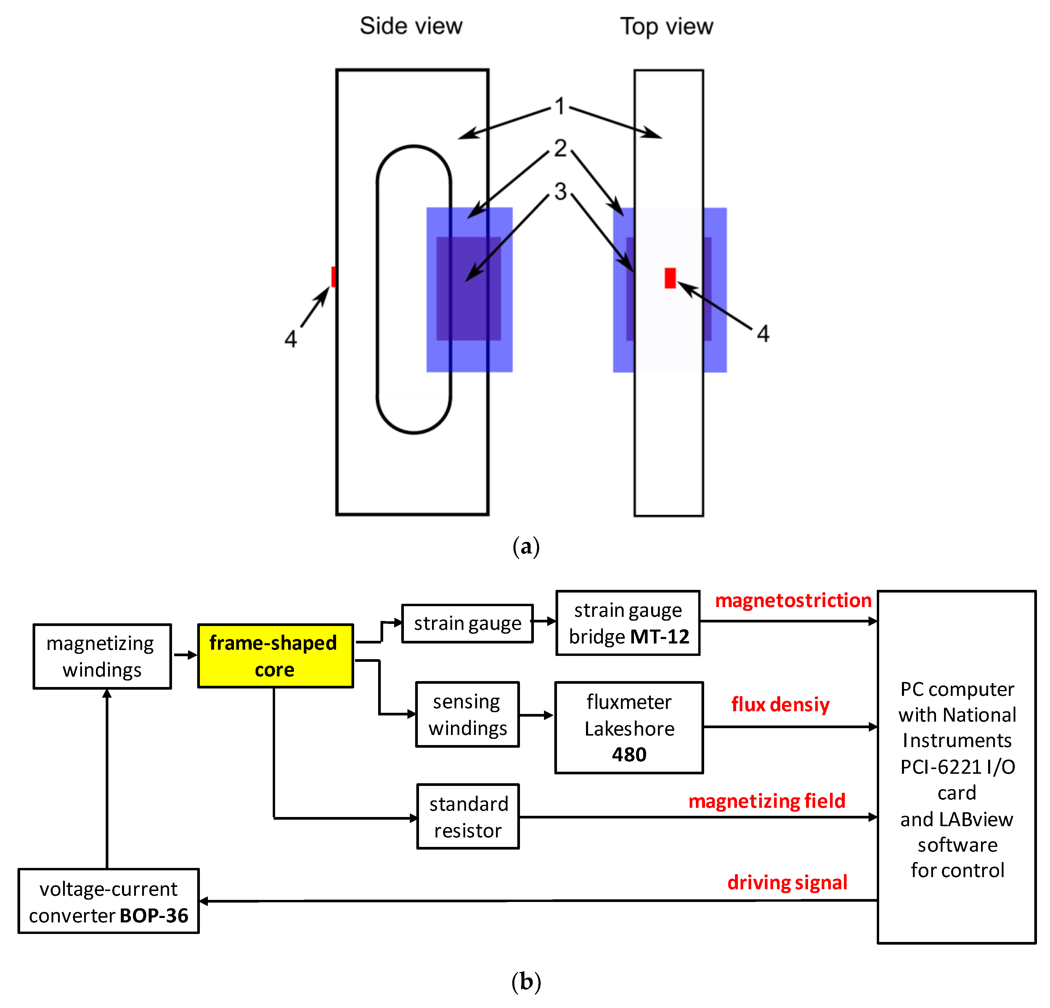
Figure 2.
The results of measurements during the single measurement cycle: (a) Magnetizing field H, (b) flux density B, (c) magnetostriction λ.
Figure 2.
The results of measurements during the single measurement cycle: (a) Magnetizing field H, (b) flux density B, (c) magnetostriction λ.

Figure 3.
Results of measurements of hysteresis loops of Mn0.70Zn0.24Fe2.06O4 ferrite for power applications: (a) B(H) magnetic hysteresis loop; (b) λ(B) magnetostrictive hysteresis loop (both magnetostrictive hysteresis and the lift-off phenomenon clearly visible).
Figure 3.
Results of measurements of hysteresis loops of Mn0.70Zn0.24Fe2.06O4 ferrite for power applications: (a) B(H) magnetic hysteresis loop; (b) λ(B) magnetostrictive hysteresis loop (both magnetostrictive hysteresis and the lift-off phenomenon clearly visible).
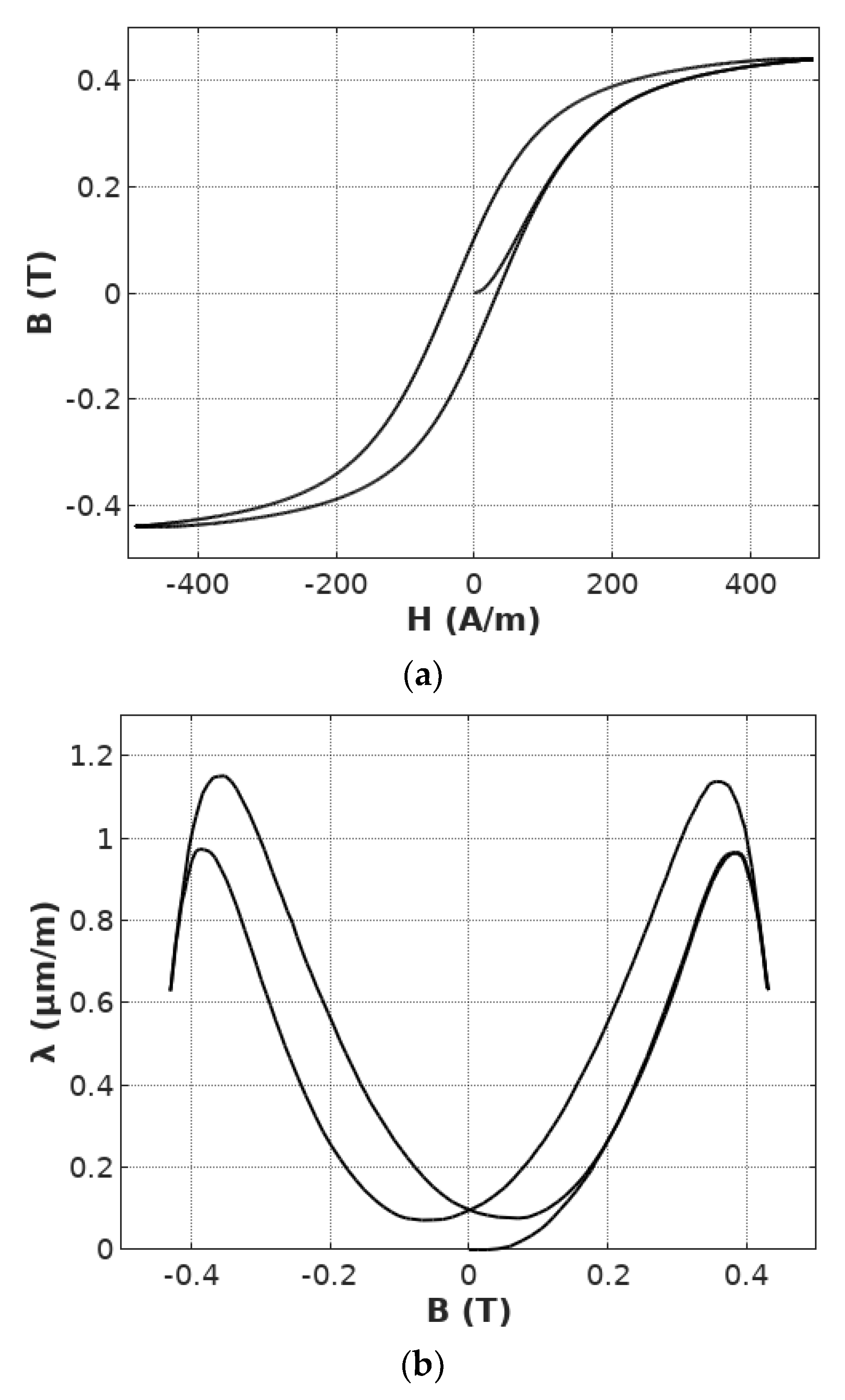
Figure 4.
The results of fitting the magnetostrictive anhysteretic curve λanhyst(B) to the results of experimental measurements of λ(B) dependence. Identified parameters: a1 = 9.3 , a2 = −90.9 , Bswitch = 0.248 T, k = 0.178.
Figure 4.
The results of fitting the magnetostrictive anhysteretic curve λanhyst(B) to the results of experimental measurements of λ(B) dependence. Identified parameters: a1 = 9.3 , a2 = −90.9 , Bswitch = 0.248 T, k = 0.178.
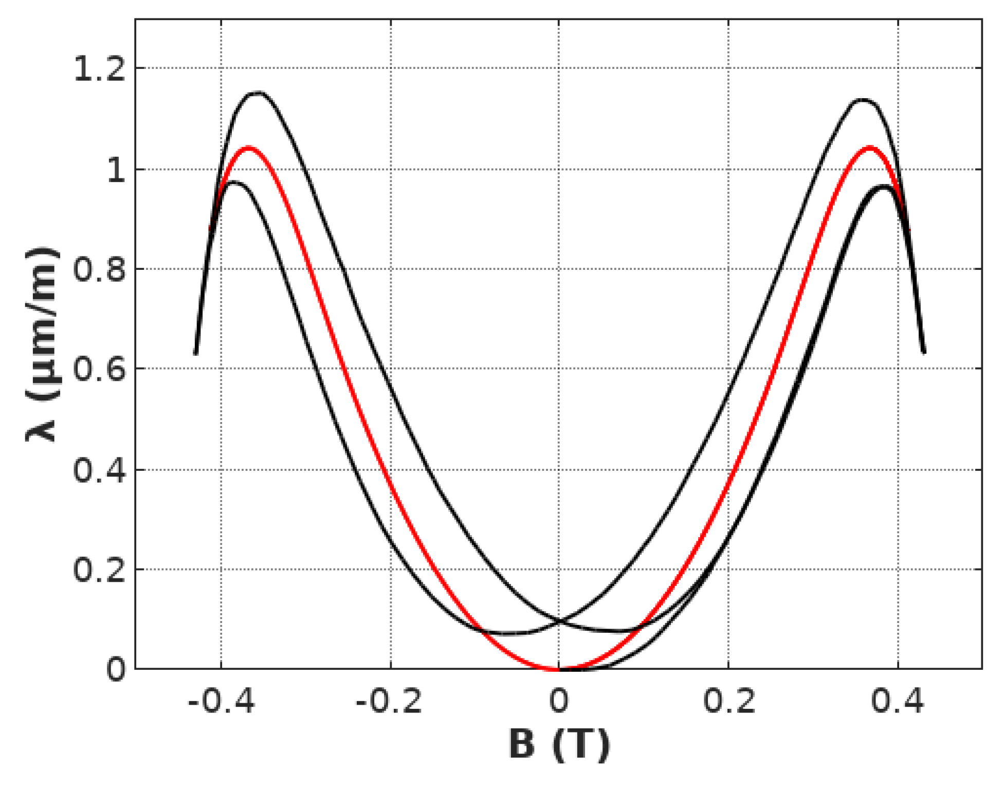
Figure 5.
Magnetostriction λ(t) signal calculated for parameters: a1 = 9.3 , a2 = −90.9 , Bswitch = 0.248 T, k = 0.178, filtered by the first order Butterworth filter for ainert equal: 2 (black), 80 (red), 200 (blue).
Figure 5.
Magnetostriction λ(t) signal calculated for parameters: a1 = 9.3 , a2 = −90.9 , Bswitch = 0.248 T, k = 0.178, filtered by the first order Butterworth filter for ainert equal: 2 (black), 80 (red), 200 (blue).
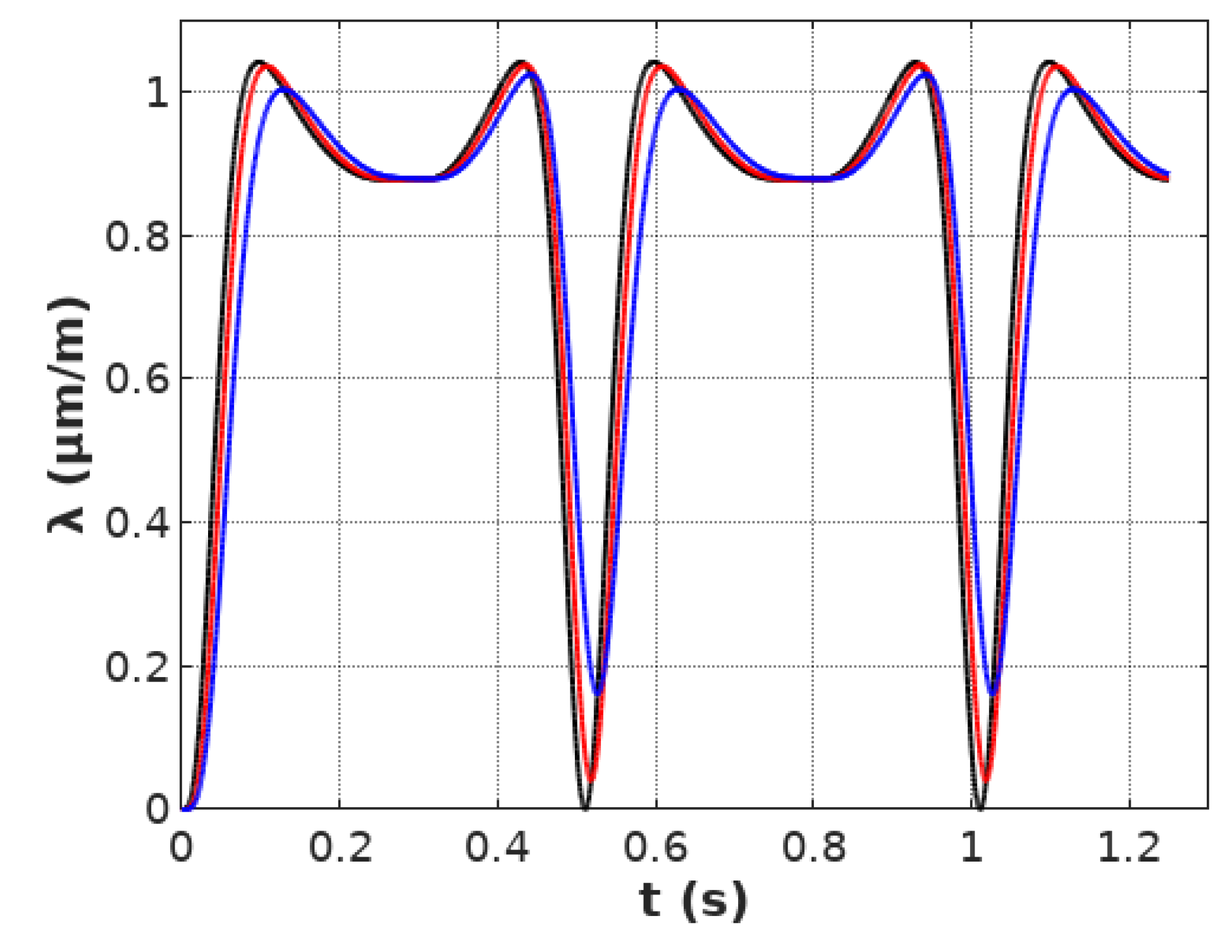
Figure 6.
Magnetostriction λ(B) hysteresis loop calculated for parameters: a1 = 9.3 , a2 = −90.9 , Bswitch = 0.248 T, k = 0.178, filtered by the first order Butterworth filter for ainert equal: 2 (black), 80 (red), 200 (blue).
Figure 6.
Magnetostriction λ(B) hysteresis loop calculated for parameters: a1 = 9.3 , a2 = −90.9 , Bswitch = 0.248 T, k = 0.178, filtered by the first order Butterworth filter for ainert equal: 2 (black), 80 (red), 200 (blue).
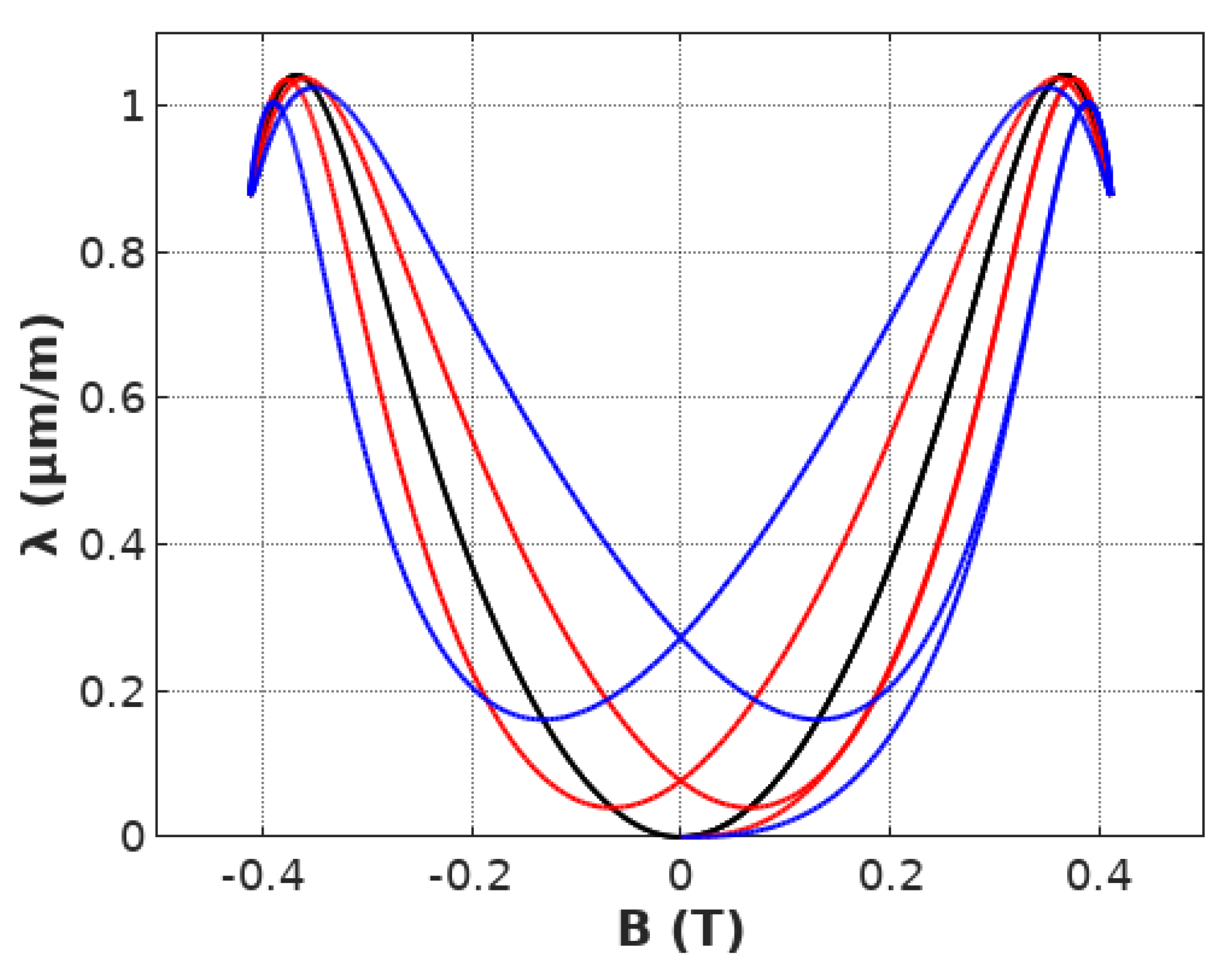
Figure 7.
Magnetostrictive B(H) hysteresis loop of Mn0.70Zn0.24Fe2.06O4 ferrite for power application modeled by the first order inertial element, calculated for the parameters: a1 = 9.3 , a2 = −90.9 , Bswitch = 0.248 T, k = 0.178 (experimental measurements—black line, results of modeling—red line).


Table 1.
Thermodynamic connections among magneto-mechanical effects [3].
Table 1.
Thermodynamic connections among magneto-mechanical effects [3].
| Effect | Thermodynamically Inverse Effect |
|---|---|
| Magnetostrictive effect Changes of the sample linear dimensions during its magnetization process [4,5] | Villari effect Changes of the sample magnetization under the compressive or tensile stresses [6,7] |
| Wiedemann effect Twisting of the magnetic wire with electric current under the longitudinal magnetic field [8,9] | Inverse Wiedemann effect Magnetization of the wire due to the twisting, in the presence of circular anisotropy [10,11] |
| Barrett effect Changes of the sample volume during its magnetization process [12,13] | Nagaoka-Honda effect Changes of the sample magnetization under the hydrostatic pressure [14,15] |
© 2019 by the author. Licensee MDPI, Basel, Switzerland. This article is an open access article distributed under the terms and conditions of the Creative Commons Attribution (CC BY) license (http://creativecommons.org/licenses/by/4.0/).
Share and Cite
MDPI and ACS Style
Szewczyk, R. Unified First Order Inertial Element Based Model of Magnetostrictive Hysteresis and Lift-Off Phenomenon. Materials 2019, 12, 1689. https://doi.org/10.3390/ma12101689
AMA Style
Szewczyk R. Unified First Order Inertial Element Based Model of Magnetostrictive Hysteresis and Lift-Off Phenomenon. Materials. 2019; 12(10):1689. https://doi.org/10.3390/ma12101689
Chicago/Turabian StyleSzewczyk, Roman. 2019. "Unified First Order Inertial Element Based Model of Magnetostrictive Hysteresis and Lift-Off Phenomenon" Materials 12, no. 10: 1689. https://doi.org/10.3390/ma12101689
Note that from the first issue of 2016, this journal uses article numbers instead of page numbers. See further details here.