Cause of Angular Distortion in Fusion Welding: Asymmetric Cross-Sectional Profile along Thickness
by
 ,
,
Deqiao Xie
1 ,
,
Jianfeng Zhao
1,*,
Huixin Liang
1,
Shuang Liu
1,2,
Zongjun Tian
1,
Lida Shen
1 and
Changjiang Wang
3 1
College of Mechanical and Electrical Engineering, Nanjing University of Aeronautics and Astronautics, Nanjing 210016, China
2
Nanjing Institution of Advanced Laser Technology, Nanjing 210038, China
3
Department of Engineering and Design, University of Sussex, Sussex House, Brighton BN1 9RH, UK
*
Author to whom correspondence should be addressed.
Materials 2019, 12(1), 58; https://doi.org/10.3390/ma12010058
Submission received: 19 November 2018
/
Revised: 17 December 2018
/
Accepted: 21 December 2018
/
Published: 24 December 2018
(This article belongs to the Section Manufacturing Processes and Systems)
Abstract
:Angular distortion is a common problem in fusion welding, especially when it comes to thick plates. Despite the fact that various processes and influencing factors have been discussed, the cause of the angular distortion has not been clearly revealed. In this research, the asymmetry of cross-sectional profile along thickness is considered of great importance to the angular distortion. A theoretical model concerning the melting-solidification process in fusion welding was established. An expression of the angular distortion was formulated and then validated by experiments of laser welding 316L stainless steel. The results show that the asymmetric cross-sectional profile is a major contributory factor towards the angular distortion mechanism. The asymmetry of cross-section profile along thickness causes the difference between two bending moments in the lower and upper parts of the joint. This is the difference that drives the angular distortion of the welded part. Besides, the asymmetry of cross-section profile is likely to be influenced by various processes and parameters, thereby changing the angular distortion.
1. Introduction
Fusion welding is a commonly used joint technology for manufacturing various metal structures, particularly within the aeronautics, automotive, ships, and architecture [1,2,3,4,5]. However, fusion welding is usually accompanied by unavoidable shrinkage and undesired distortion, which can decrease the precision of the welded part [6,7].
According to Zhou, angular distortion is a common distortion in fusion welding [8]. He concluded several factors were related including plate thickness, total heat input, amount of weld metal used, and groove shape. Wang et al. [9] investigated that angular distortion could be distinctly changed by heat input and plate thickness. Okano et al. [10] and Tian et al. [11] observed that angular distortion could be decreased when the heat input was larger. However, Adamczuk et al. [12] discovered that angular distortion may not be affected by heat input. In terms of the amount of weld metal, angular distortion was more dominant in multi-pass welding than that in single-pass welding [13]. Cai et al. [14] revealed that angular distortion in butt-joint welding of V-groove items was larger than that of X-groove.
Researchers also explored other processes and parameters that could change angular distortion in welding. Zhang et al. [15] found a nonlinear relationship between angular distortion and arc distance. Tseng and Chou [16] found that angular distortion increased with the proportion of nitrogen in the shielding gas for welding austenitic stainless steel. The austenitic matrix is beneficial for reducing angular distortion. Thermal expansion coefficient is also recognized as a significant parameter for accurate predictions of angular distortion [17]. Park et al. [18] found that pre-tension stress loaded in the transversal direction diminished welding angular distortion by 60%. Kelly et al. [19] stated that the laser-arc hybrid welding obtained less distortion compared with arc welding. Rong et al. [20] applied a magnetic field in laser welding. The welding distortion was decreased by 26.56%. Mochizuki et al. [21] found that reverse-side TIG heating ahead of MIG welding was able to reduce angular distortion. Michaleris [22] pointed out several ways to reduce angular distortion including presetting, restraint, and line heating.
Researchers have shown that the factors are various and complicated which could change the angular distortion in welding. But the following remain unknown: (1) How to judge the directions of angular distortion. (2) How do the factors directly change and to what extent can such factors change the angular distortion? (3) Whether the angular distortion can be expressed in a calculation. This study aims to reveal the mechanism of angular distortion in fusion welding and how the welding processes and factors influence the angular distortion In this study, a theoretical model concerning the melting-solidification process in fusion welding will be established. An expression of the angular distortion will be formulated and then validated by laser welding 316L austenitic stainless steel. Based on the research, the angular distortion will be controlled and adjusted with a quantitative guideline.
2. Theoretical Model
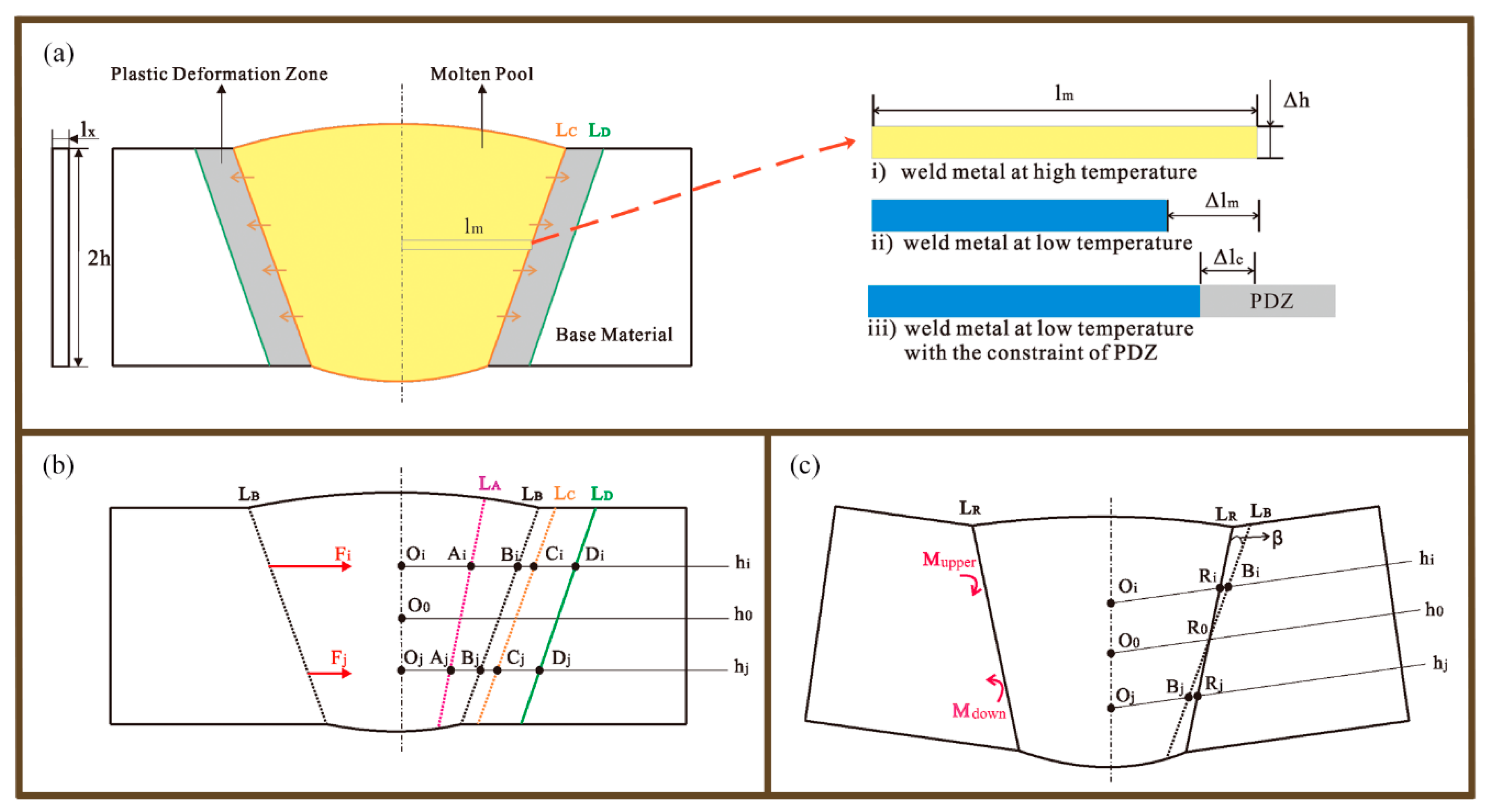
A theoretical model of the angular distortion in fusion welding is demonstrated in Figure 1. Figure 1a shows the schematic diagram of a weld seam cross-section when the metal was melted. Adequate high energy input, like arc, laser, and electron beam, heated the metal to form a molten pool. The metal in the molten pool was expanded, resulting in the compression of the base material adjacent to boundary of the molten pool. The base material heat-affected by the molten pool was easily plastically deformed [23,24]. The plastic deformation zone (PDZ) can be assumed between the lines LC and LD.
After the heat input was removed, the molten pool cooled down and then shrunk. However, the shrinkage had to be restricted by the PDZ. The right region of Figure 1a illustrates this phenomenon in a specific way. The length of a rod extracted from the molten pool was lm when the metal was at a high temperature. If there was no constraint, the rod could shrink to Δlm after it cooled. However, the material at the PDZ had been compressed before. The PDZ had to be stretched in a reverse direction for the shrinkage of weld metal. There would be an equilibrium between the rod and the PDZ. Finally, the rod had a shrinkage of Δlc with the constraint of PDZ. An interactive constraining force can be assumed between the rod and PDZ [25].
Since the weld metal in the cross-section can be divided into a mass of rods at different heights, there would be associated constraining forces at associated heights between weld metal and the PDZ. Figure 1b shows two typical constraining forces at heights of hi and hj. The hi and hj represent the heights above and down the center line h0 respectively. Line LA depicted the ideal boundary of the weld metal if there was no constraint. Line LB was the actual boundary of the weld metal with the constraint of the PDZ if angular distortion was not generated. The rods at different heights were assumed to be ideal elastic bodies. According to Hooke’s law, the constraining force Fi is expressed as below.
E is the Young’s modulus of weld metal. represents the cross-section area of the rod. The ideal shrinkage is composed of thermal shrinkage and phase transformation shrinkage βpt [26]. The α is thermal expansion coefficient of the weld metal, while ∆T represents the temperature difference between solidus temperature and room temperature.
The represents the length after equilibrium of weld metal’s shrinkage and the PDZ’s stretch. The PDZ was more difficult to be stretched, because it was colder and had been severely compressed before. Wang [24] reported a tiny backward stretch of the PDZ after an obvious compressive plastic strain. Therefore, we assume that the PDZ dominates the equilibrium, and the reflects the capacity of reverse stretch of the PDZ. The relationship between and PDZ is assumed to be:
k is the coefficient about reverse stretch of PDZ. It may be determined by the welded metal properties like thermal expansion and plasticity. So, the constraining forces Fi and Fj can be expressed more specifically as below:
As expressed in Formulas (6) and (7), the bending moments Mupper and Mdown derived from the constraining forces in the upper and lower parts of the cross-section, respectively. If the Mupper was different from Mdown, the base material was driven to rotate, forming an angular distortion β. The final boundary of cross-section LR was depicted in Figure 1d. The Fi and Fj should be amended as follows:
The bending moment Mupper would be equal to Mdown finally.
So, the angular distortion β can be formulated as below.
Zhou’s study [27] showed isothermal curve parallel to the cross-section profile in laser welding. So, and in Formula (14) are regarded to be the same as . The other part in Formula (14) was replaced by , as shown in Formulas (15) and (16). It can be seen that the angular distortion β is decomposed by three parts: weld metal properties, length of plastic deformation zone, and cross-section profile of weld seam. Here, reflects the length of plastic deformation zone (PDZ) that caused by expansion of the molten pool in welding. The k is determined by the weld material properties. reflects the difference between upper and down parts of weld seam cross-section, i.e., the asymmetry of the cross-sectional profile along thickness. Zhou was very close to this finding because he mentioned that angular distortion was caused by temperature differences between the top and bottom surfaces of the plate [8].
3. Experimental
Laser has been widely utilized in automatic welding for automotive, electronics, and aircrafts [28]. Laser welding is an attractive option because laser is stable and repeatable. In this experiment, austenitic stainless steel AISI 316L (EN 1.4404) was used, as it is a commonly used austenitic stainless steel within marine, energy, aerospace, and medical environments due to its excellent strength and corrosion resistance performances [29,30].
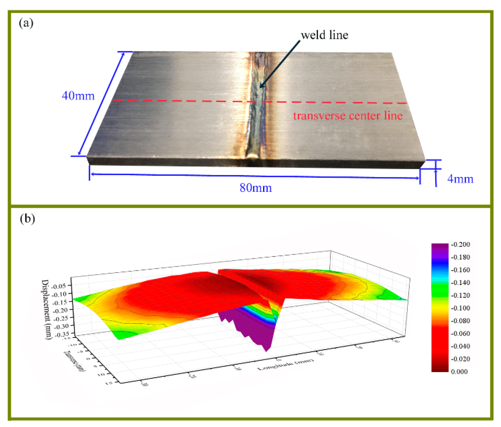
The experiment was performed on a laser welding system consisting of a 6 kW TRUMPF disk laser (Trumpf Co. ltd, Ditzingen, Germany) with working wavelength of 1064 nm, a KUKA robot (Kuka Robot, Augsburg, Germany), and a PRECITEC welding head (Precitec GmbH, Gaggenau, Germany). The molten pool was shielded by argon gas. The 80 mm × 40 mm × 4 mm AISI 316L plates (Haocheng, Shanghai, China) were welded, as shown in Figure 2a. The parts were welded at a velocity of 15 mm/s.
The distortion of the substrate was measured by a coordinate measuring machine from Leader Metrology Inc., MD, America. The displacement data of a 2 mm × 2 mm dot matrix on the back of the substrate was obtained. The measured data were used to create 3D contour plot with Origin Software, so as to demonstrate the distortion intuitively. Figure 2b shows software morphology reconstruction of the bottom surface of case S1. It depicts a symmetrical and downward distortion of the butt-joint laser welding. The data at transverse center line were also extracted.
In order to investigate the cross-sectional profile, the cases were cut via wire-Electrical Discharging Machining(EDM) (Huafang, Hangzhou, China)EDM. The microstructure was observed on an OLYMPUSGX71 optical microscope (Olympus Corporation, Tokyo, Japan) after using the etchant of 5g CuCl2 +100 mL HCl + 100 mL CH3CH2OH.
4. Results and Discussion
4.1. The Cross-Sectional Profiles of S1–S6 Cases
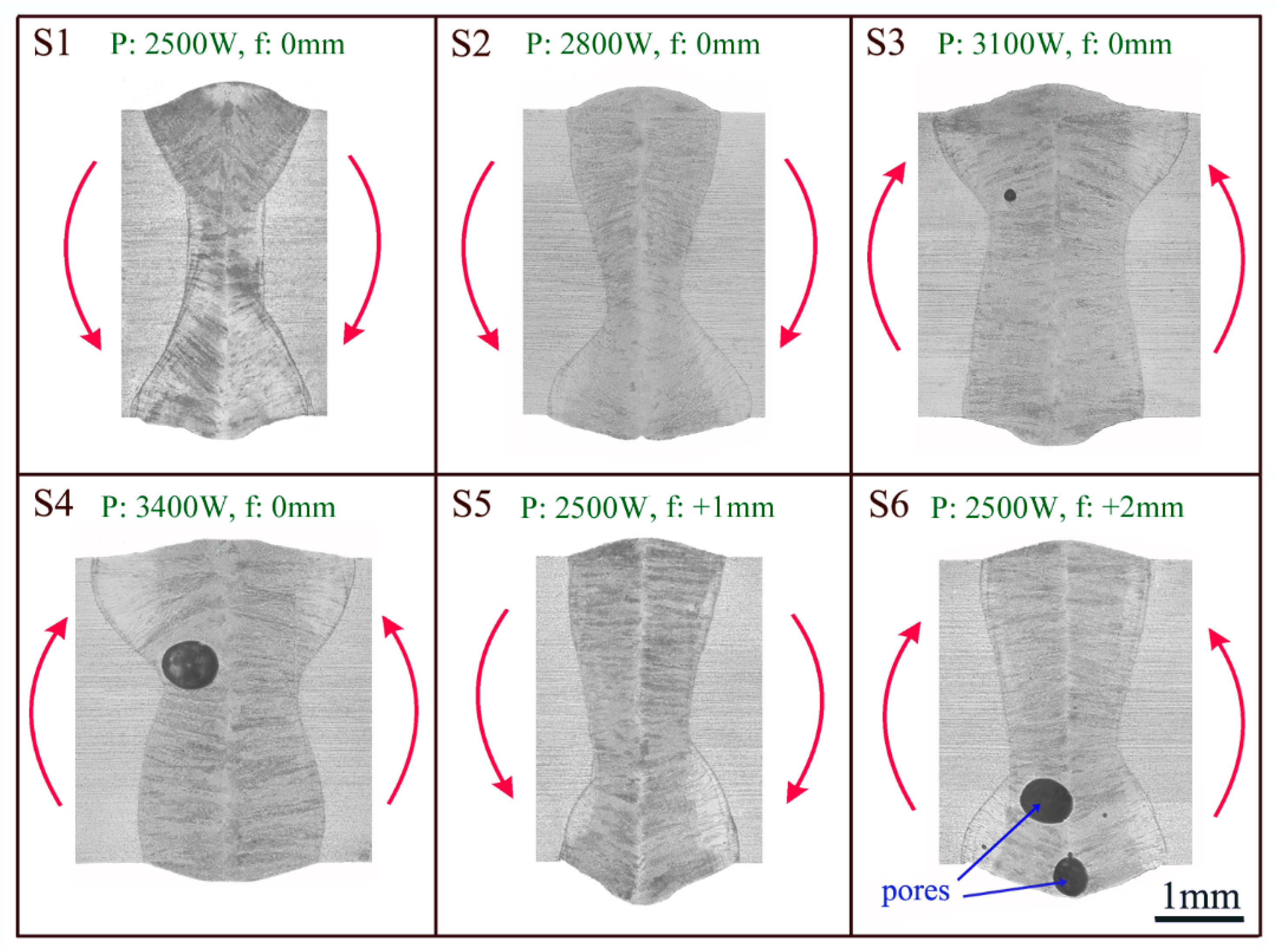
Based on Formulas (15) and (16), we can quickly judge that if the down section of profile was broader than the upper section, angular distortion β in Formula (14) would be negative, and vice versa. The broader profile in down section meant that was generally longer than , resulting in a negative angular distortion like case S1 in Figure 3.
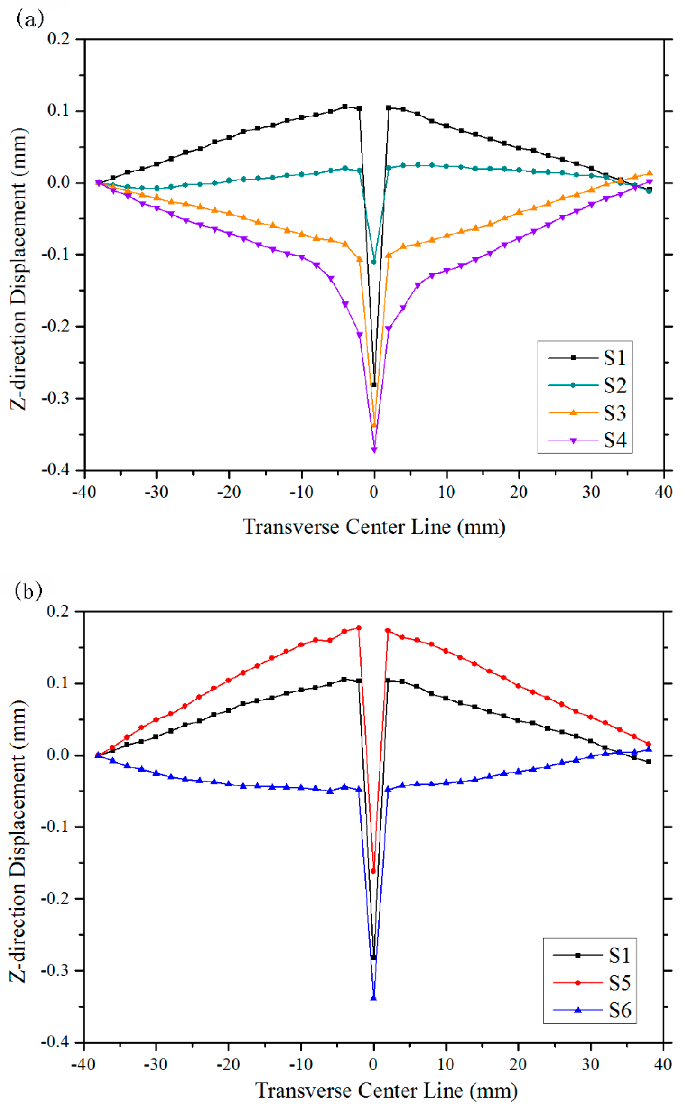
Figure 3 also reveals that the upper section became wider as laser power increased, as shown by cases S1 S2, S3, and S4. Hence, it can be predicted that the angular distortion would become gradually upward. The estimation was later validated by Figure 4a, which shows Z-direction displacements of transverse center lines of cases S1–S4. It can be inferred that the asymmetric cross-sectional profile along thickness is a major contributory factor towards angular distortion mechanism.
When the focus offset increased, as seen in S1, S5, and S6, the down section profile became larger. So, case S5 obtained a more obvious downward angular distortion than S1. But for S6, the excessive focus offset tended to decrease the density of the laser power, which led to insufficient flow in the molten pool. As a result, the pores were hard to flee. The big pores at the lower section released the constraint between weld metal and the PDZ to a certain extent. The bending moment of upper section Mupper could drive base material to bend upward, as depicted in Figure 4b.
4.2. Calculation of the Angular Distortion
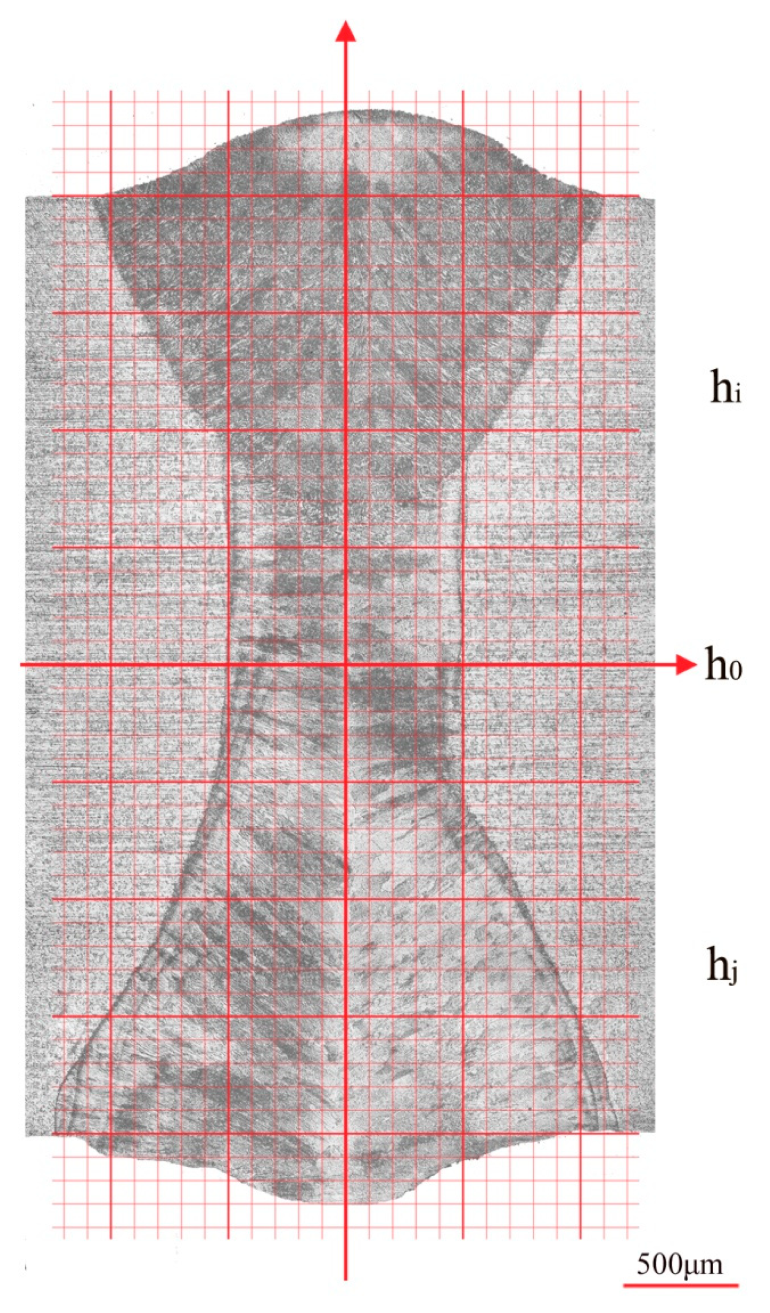
In order to obtain the data of profile asymmetry, a cartesian coordinate system was established upon the cross-section image, as shown in Figure 5. The lengths of the at different heights hi above the center line h0 were measured, as well as lengths of the at different heights hj down h0. Table 1 shows the cross-section profile of case S1.
The profiles of cases S2–S6 were shown in supplementary Table A1, Table A2, Table A3, Table A4 and Table A5 (refer to Appendix A). Table 2 exhibits the calculated and and , as well as the measured angular distortions of cases S1–S6. The nonlinear Z-direction displacement near weld line revealed the PDZ, for example the region from −12 mm to 12 mm on the transverse center line of case S6. The regions from −30 mm to −20 mm and from 20 mm to 30 mm of transverse center line are thought to reflect the real angular distortion of the cases, because the connection lines lie on nearly same straight lines. βaverage was the average value of βleft and βright.
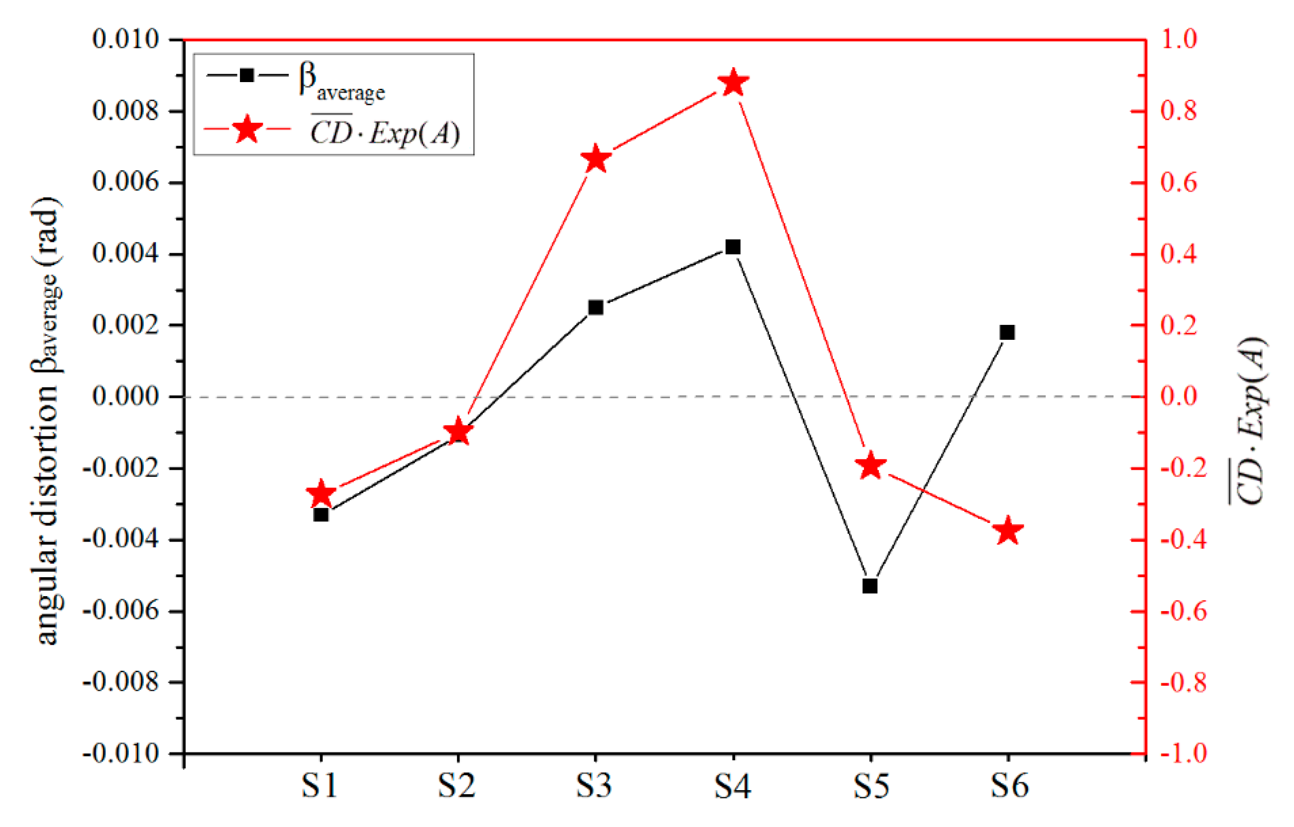
Figure 6 demonstrates the relationship between calculated and measured angular distortions of cases S1–S6. The calculated verified angular distortion directions of cases S1–S5 quite well. However, the pores in case S6 distinctly changed the predicted direction. The errors between the calculated and the measured values may come from the undesired pores, the inaccurate estimation of the PDZ length and the inhomogeneous microstructure of the weld seam, which can affect the elastic and plastic performances. Further studies are required for more accurate calculation of angular distortion.
5. Conclusions
Previous studies have shown that angular distortion can be influenced by various processes and parameters. However, the cause of angular distortion remains unclear. In this study, the influence of cross-sectional profile on the angular distortion is firstly valued. The authors established a theoretical model to illustrate the melting-solidification process in laser welding, and then formulated an expression of the angular distortion. The calculation process of angular distortion was shown based on cases S1–S6. The experimental results matched the theoretical findings well. The conclusions are as follows:
(1) The asymmetry of the cross-sectional profile causes the difference between bending moments Mupper and Mdown, thereby causing the angular distortion. The angular distortion direction depends on whether the broader profile is at upper or at down section of the weld beam.
(2) The angular distortion seems to be related to weld metal properties, length of plastic deformation zone and, most important, the asymmetry of the cross-sectional profile along thickness.
(3) The various processes and parameters can change the asymmetry of the cross-sectional profile, which will change the angular distortion. It is promising to minimize the angular distortion by decreasing the difference between the upper and lower profile of the weld seam.
(4) The pores in the weld seam can distinctly change the direction and value of predicted welding angular distortion.
Author Contributions
Conceptualization, J.Z.; Methodology, H.L. and S.L.; Writing-Review and Editing, C.W.; Validation, Z.T. and L.S.
Funding
This work was supported by the National Key Research and Development Program “Additive Manufacturing and Laser Manufacturing” (No. 2018YFB1105400), the National Natural Science Foundation of China (No. 51475238, and 51605473), and the Key Research and Development Program of Jiangsu Provincial Department of Science and Technology of China (Nos. BE2015161, BE2015029 and BE2016010-3).
Conflicts of Interest
The authors declare no conflicts of interest.
Appendix A

Table A1.
Cross-sectional profile of case S2 weld seam. (Unit: mm).
| Height Upper (hi) | Left Length | Right Length | Average Length (OiRi) | Height Down (hj) | Left Length | Right Length | Average Length (OjRj) |
|---|---|---|---|---|---|---|---|
| 0.1 | 0.65 | 0.53 | 0.59 | 0.1 | 0.60 | 0.50 | 0.55 |
| 0.2 | 0.68 | 0.58 | 0.63 | 0.2 | 0.58 | 0.50 | 0.54 |
| 0.3 | 0.73 | 0.62 | 0.68 | 0.3 | 0.56 | 0.50 | 0.53 |
| 0.4 | 0.76 | 0.64 | 0.70 | 0.4 | 0.53 | 0.50 | 0.515 |
| 0.5 | 0.78 | 0.65 | 0.72 | 0.5 | 0.52 | 0.50 | 0.51 |
| 0.6 | 0.82 | 0.68 | 0.75 | 0.6 | 0.52 | 0.55 | 0.535 |
| 0.7 | 0.85 | 0.72 | 0.79 | 0.7 | 0.53 | 0.62 | 0.575 |
| 0.8 | 0.88 | 0.76 | 0.82 | 0.8 | 0.58 | 0.70 | 0.64 |
| 0.9 | 0.93 | 0.80 | 0.87 | 0.9 | 0.64 | 0.80 | 0.72 |
| 1.0 | 0.97 | 0.85 | 0.91 | 1.0 | 0.72 | 0.90 | 0.81 |
| 1.1 | 1.00 | 0.88 | 0.94 | 1.1 | 0.81 | 1.00 | 0.905 |
| 1.2 | 1.03 | 0.90 | 0.97 | 1.2 | 0.93 | 1.10 | 1.015 |
| 1.3 | 1.04 | 0.92 | 0.98 | 1.3 | 1.04 | 1.18 | 1.11 |
| 1.4 | 1.04 | 0.94 | 0.99 | 1.4 | 1.15 | 1.22 | 1.185 |
| 1.5 | 1.04 | 0.95 | 1.00 | 1.5 | 1.22 | 1.30 | 1.26 |
| 1.6 | 1.05 | 0.97 | 1.01 | 1.6 | 1.25 | 1.35 | 1.3.0 |
| 1.7 | 1.07 | 0.99 | 1.03 | 1.7 | 1.28 | 1.4 | 1.34 |
| 1.8 | 1.09 | 1.00 | 1.05 | 1.8 | 1.33 | 1.45 | 1.39 |
| 1.9 | 1.10 | 1.00 | 1.05 | 1.9 | 1.35 | 1.44 | 1.395 |
| 2.0 | 1.10 | 1.00 | 1.05 | 2.0 | 1.35 | 1.42 | 1.385 |
| 0 | 0.62 | 0.50 | 0.56 |
Table A2.
Cross-sectional profile of case S3 weld seam. (Unit: mm).
| Height Upper (hi) | Left Length | Right Length | Average Length (OiRi) | Height Down (hj) | Left Length | Right Length | Average Length (OjRj) |
|---|---|---|---|---|---|---|---|
| 0.1 | 0.95 | 0.96 | 0.955 | 0.1 | 0.98 | 0.98 | 0.98 |
| 0.2 | 0.90 | 0.96 | 0.93 | 0.2 | 1.00 | 1.00 | 1.00 |
| 0.3 | 0.88 | 0.98 | 0.93 | 0.3 | 1.02 | 1.00 | 1.01 |
| 0.4 | 0.88 | 1.00 | 0.94 | 0.4 | 1.04 | 1.00 | 1.02 |
| 0.5 | 0.87 | 1.00 | 0.935 | 0.5 | 1.05 | 1.02 | 1.04 |
| 0.6 | 0.90 | 1.04 | 0.97 | 0.6 | 1.08 | 1.04 | 1.06 |
| 0.7 | 0.98 | 1.08 | 1.03 | 0.7 | 1.10 | 1.08 | 1.09 |
| 0.8 | 1.05 | 1.16 | 1.105 | 0.8 | 1.12 | 1.10 | 1.11 |
| 0.9 | 1.13 | 1.25 | 1.19 | 0.9 | 1.13 | 1.12 | 1.13 |
| 1.0 | 1.25 | 1.33 | 1.29 | 1.0 | 1.13 | 1.13 | 1.13 |
| 1.1 | 1.32 | 1.46 | 1.39 | 1.1 | 1.15 | 1.15 | 1.15 |
| 1.2 | 1.41 | 1.55 | 1.48 | 1.2 | 1.16 | 1.17 | 1.17 |
| 1.3 | 1.47 | 1.60 | 1.535 | 1.3 | 1.17 | 1.18 | 1.18 |
| 1.4 | 1.52 | 1.68 | 1.60 | 1.4 | 1.18 | 1.20 | 1.19 |
| 1.5 | 1.58 | 1.74 | 1.66 | 1.5 | 1.2 | 1.21 | 1.21 |
| 1.6 | 1.62 | 1.77 | 1.695 | 1.6 | 1.21 | 1.22 | 1.22 |
| 1.7 | 1.66 | 1.82 | 1.74 | 1.7 | 1.23 | 1.23 | 1.23 |
| 1.8 | 1.69 | 1.82 | 1.755 | 1.8 | 1.26 | 1.24 | 1.25 |
| 1.9 | 1.70 | 1.82 | 1.76 | 1.9 | 1.26 | 1.24 | 1.25 |
| 2.0 | 1.70 | 1.8 | 1.75 | 2.0 | 1.26 | 1.20 | 1.23 |
| 0 | 0.96 | 1.00 | 0.98 |
Table A3.
Cross-sectional profile of case S4 weld seam. (Unit: mm).
| Height Upper (hi) | Left Length | Right Length | Average Length (OiRi) | Height Down (hj) | Left Length | Right Length | Average Length (OjRj) |
|---|---|---|---|---|---|---|---|
| 0.1 | 0.95 | 0.96 | 0.955 | 0.1 | 1.00 | 1.00 | 1.00 |
| 0.2 | 0.88 | 0.98 | 0.93 | 0.2 | 1.02 | 1.02 | 1.02 |
| 0.3 | 0.86 | 0.99 | 0.925 | 0.3 | 1.09 | 1.05 | 1.07 |
| 0.4 | 0.92 | 1.00 | 0.96 | 0.4 | 1.11 | 1.10 | 1.11 |
| 0.5 | 0.98 | 1.02 | 1.00 | 0.5 | 1.12 | 1.13 | 1.13 |
| 0.6 | 1.06 | 1.08 | 1.07 | 0.6 | 1.14 | 1.18 | 1.16 |
| 0.7 | 1.17 | 1.20 | 1.185 | 0.7 | 1.17 | 1.20 | 1.19 |
| 0.8 | 1.28 | 1.25 | 1.265 | 0.8 | 1.19 | 1.22 | 1.21 |
| 0.9 | 1.39 | 1.34 | 1.365 | 0.9 | 1.2 | 1.25 | 1.23 |
| 1.0 | 1.50 | 1.43 | 1.465 | 1.0 | 1.2 | 1.28 | 1.24 |
| 1.1 | 1.54 | 1.48 | 1.51 | 1.1 | 1.22 | 1.30 | 1.26 |
| 1.2 | 1.66 | 1.53 | 1.595 | 1.2 | 1.22 | 1.30 | 1.26 |
| 1.3 | 1.74 | 1.58 | 1.66 | 1.3 | 1.22 | 1.32 | 1.27 |
| 1.4 | 1.78 | 1.60 | 1.69 | 1.4 | 1.23 | 1.32 | 1.28 |
| 1.5 | 1.82 | 1.66 | 1.74 | 1.5 | 1.22 | 1.32 | 1.27 |
| 1.6 | 1.86 | 1.68 | 1.77 | 1.6 | 1.21 | 1.32 | 1.27 |
| 1.7 | 1.87 | 1.72 | 1.795 | 1.7 | 1.200 | 1.31 | 1.26 |
| 1.8 | 1.88 | 1.73 | 1.805 | 1.8 | 1.18 | 1.29 | 1.24 |
| 1.9 | 1.86 | 1.74 | 1.80 | 1.9 | 1.17 | 1.27 | 1.22 |
| 2.0 | 1.84 | 1.72 | 1.78 | 2.0 | 1.15 | 1.24 | 1.20 |
| 0 | 1.00 | 1.00 | 1.00 |
Table A4.
Cross-sectional profile of case S5 weld seam. (Unit: mm).
| Height Upper (hi) | Left Length | Right Length | Average Length (OiRi) | Height Down (hj) | Left Length | Right Length | Average Length (OjRj) |
|---|---|---|---|---|---|---|---|
| 0.1 | 0.70 | 0.65 | 0.675 | 0.1 | 0.68 | 0.64 | 0.66 |
| 0.2 | 0.70 | 0.68 | 0.69 | 0.2 | 0.68 | 0.64 | 0.66 |
| 0.3 | 0.75 | 0.70 | 0.725 | 0.3 | 0.65 | 0.64 | 0.645 |
| 0.4 | 0.76 | 0.72 | 0.74 | 0.4 | 0.63 | 0.68 | 0.655 |
| 0.5 | 0.78 | 0.74 | 0.76 | 0.5 | 0.60 | 0.74 | 0.67 |
| 0.6 | 0.79 | 0.76 | 0.775 | 0.6 | 0.60 | 0.82 | 0.71 |
| 0.7 | 0.81 | 0.78 | 0.795 | 0.7 | 0.60 | 0.88 | 0.74 |
| 0.8 | 0.84 | 0.82 | 0.83 | 0.8 | 0.62 | 0.96 | 0.79 |
| 0.9 | 0.86 | 0.86 | 0.86 | 0.9 | 0.63 | 1.02 | 0.825 |
| 1.0 | 0.89 | 0.89 | 0.89 | 1.0 | 0.69 | 1.06 | 0.875 |
| 1.1 | 0.92 | 0.92 | 0.92 | 1.1 | 0.77 | 1.10 | 0.935 |
| 1.2 | 0.92 | 0.93 | 0.925 | 1.2 | 0.85 | 1.14 | 0.995 |
| 1.3 | 0.92 | 0.95 | 0.935 | 1.3 | 0.89 | 1.17 | 1.03 |
| 1.4 | 0.92 | 0.97 | 0.945 | 1.4 | 0.93 | 1.21 | 1.07 |
| 1.5 | 0.92 | 1.02 | 0.97 | 1.5 | 0.95 | 1.24 | 1.095 |
| 1.6 | 0.92 | 1.05 | 0.985 | 1.6 | 0.98 | 1.26 | 1.12 |
| 1.7 | 0.92 | 1.06 | 0.99 | 1.7 | 0.99 | 1.28 | 1.135 |
| 1.8 | 0.93 | 1.08 | 1.005 | 1.8 | 1.03 | 1.32 | 1.175 |
| 1.9 | 0.95 | 1.10 | 1.025 | 1.9 | 1.05 | 1.32 | 1.185 |
| 2.0 | 0.96 | 1.12 | 1.04 | 2.0 | 1.06 | 1.32 | 1.19 |
| 0 | 0.68 | 0.66 | 0.67 |
Table A5.
Cross-sectional profile of case S6 weld seam. (Unit: mm).
| Height Upper (hi) | Left Length | Right Length | Average Length (OiRi) | Height Down (hj) | Left Length | Right Length | Average Length (OjRj) |
|---|---|---|---|---|---|---|---|
| 0.1 | 0.70 | 0.72 | 0.71 | 0.1 | 0.70 | 0.78 | 0.74 |
| 0.2 | 0.74 | 0.72 | 0.73 | 0.2 | 0.70 | 0.78 | 0.74 |
| 0.3 | 0.76 | 0.74 | 0.75 | 0.3 | 0.70 | 0.78 | 0.74 |
| 0.4 | 0.78 | 0.76 | 0.77 | 0.4 | 0.70 | 0.82 | 0.76 |
| 0.5 | 0.80 | 0.78 | 0.79 | 0.5 | 0.70 | 0.86 | 0.78 |
| 0.6 | 0.82 | 0.80 | 0.81 | 0.6 | 0.72 | 0.88 | 0.80 |
| 0.7 | 0.80 | 0.82 | 0.81 | 0.7 | 0.74 | 0.93 | 0.835 |
| 0.8 | 0.90 | 0.84 | 0.87 | 0.8 | 0.78 | 0.96 | 0.87 |
| 0.9 | 0.94 | 0.87 | 0.905 | 0.9 | 0.84 | 0.98 | 0.91 |
| 1.0 | 0.98 | 0.90 | 0.94 | 1.0 | 0.90 | 1.00 | 0.95 |
| 1.1 | 1.00 | 0.92 | 0.96 | 1.1 | 0.95 | 1.02 | 0.985 |
| 1.2 | 1.02 | 0.94 | 0.98 | 1.2 | 0.98 | 1.10 | 1.04 |
| 1.3 | 1.04 | 0.97 | 1.005 | 1.3 | 1.04 | 1.20 | 1.12 |
| 1.4 | 1.06 | 1.00 | 1.03 | 1.4 | 1.10 | 1.28 | 1.19 |
| 1.5 | 1.08 | 1.03 | 1.055 | 1.5 | 1.17 | 1.34 | 1.255 |
| 1.6 | 1.08 | 1.06 | 1.07 | 1.6 | 1.20 | 1.42 | 1.31 |
| 1.7 | 1.08 | 1.07 | 1.075 | 1.7 | 1.22 | 1.46 | 1.34 |
| 1.8 | 1.08 | 1.08 | 1.08 | 1.8 | 1.23 | 1.48 | 1.355 |
| 1.9 | 1.08 | 1.09 | 1.085 | 1.9 | 1.25 | 1.50 | 1.375 |
| 2.0 | 1.08 | 1.09 | 1.085 | 2.0 | 1.28 | 1.50 | 1.39 |
| 0 | 0.64 | 0.70 | 0.67 |
References
- Kumar, U.; Gope, D.; Srivastava, J.; Chattopadhyaya, S.; Das, A.; Krolczyk, G. Experimental and Numerical Assessment of Temperature Field and Analysis of Microstructure and Mechanical Properties of Low Power Laser Annealed Welded Joints. Materials 2018, 11, 1514. [Google Scholar] [CrossRef] [PubMed]
- Hazvinloo, H.R.; Honarbakhsh, R.A. Effect of gas-shielded flux cored arc welding parameters on weld width and tensile properties of weld metal in a low carbon steel. J. Appl. Sci. 2010, 10, 658–663. [Google Scholar]
- Wen, C.; Wang, Z.; Deng, X.; Wang, G.; Misra, R.D.K. Effect of Heat Input on the Microstructure and Mechanical Properties of Low Alloy Ultra-High Strength Structural Steel Welded Joint. Steel. Res. Int. 2018, 89. [Google Scholar] [CrossRef]
- Gery, D.; Long, H.; Maropoulos, P. Effects of welding speed, energy input and heat source distribution on temperature variations in butt joint welding. J. Mater. Process. Technol. 2005, 167, 393–401. [Google Scholar] [CrossRef]
- Armentani, E.; Esposito, R.; Sepe, R. The influence of thermal properties and preheating on residual stresses in welding. Int. J. Surf. Sci. Eng. 2007, 1, 146–162. [Google Scholar] [CrossRef]
- Souto, J.; Ares, E.; Alegre, P.; Cerqueiro, J. Methodology to Reduce Distortion Using a Hybrid Thermal Welding Process. Materials 2018, 11, 1649. [Google Scholar] [CrossRef] [PubMed]
- Yang, Y.; Wu, P.; Wang, Q.; Wu, H.; Liu, Y.; Deng, Y.; Zhou, Y.; Shuai, C. The enhancement of Mg corrosion resistance by alloying Mn and laser-melting. Materials 2016, 9, 216. [Google Scholar] [CrossRef] [PubMed]
- Ye, Z. Analysis of Welding Distortion Using Qualitative and Semi-Quantitative Techniques; The University of British Columbia: Vancouver, BC, Canada, 1998. [Google Scholar]
- Wang, R.; Rashed, S.; Serizawa, H.; Murakawa, H.; Zhang, J. Study on welding inherent deformations in welded structural materials. Trans. JWRI 2008, 37, 91–100. [Google Scholar] [CrossRef]
- Okano, S.; Mochizuki, M.; Yamamoto, K.; Tanaka, M. An attempt to enhance numerical models of angular distortion by considering the physics of the welding arc. Weld World 2011, 55, 93–100. [Google Scholar] [CrossRef]
- Tian, L.; Luo, Y.; Wang, Y.; Wu, X. Prediction of transverse and angular distortions of gas tungsten arc bead-on-plate welding using artificial neural network. Mater. Des. 2014, 54, 458–472. [Google Scholar] [CrossRef]
- Cezar, A.; Ivan, G.M.; Jose, A.E.M. Methodology for predicting the angular distortion in multi-pass butt-joint welding. J. Mater. Process. Technol. 2017, 240, 305–313. [Google Scholar] [CrossRef]
- Vel Murugan, V.; Gunaraj, V. Effects of process parameters on angular distortion of gas metal arc welded structural steel plates. Weld J. 2005, 84, 165–170. [Google Scholar]
- Cai, J.; Ye, Y.; Deng, Y.; Zhang, D. Study on Influences of Groove Type on Welding Residual Stress and Deformation in Q345/SUS304 Dissimilar Steel Butt-welded Joints. J. Mech. Eng. 2015, 51, 55. [Google Scholar] [CrossRef]
- Zhang, H.; Zhang, G.; Cai, C.; Gao, H.; Wu, L. Fundamental studies on in-process controlling angular distortion in asymmetrical double-sided double arc welding. J. Mater. Process. Technol. 2008, 205, 214–223. [Google Scholar] [CrossRef]
- Tseng, K.H.; Chou, C.P. The study of nitrogen in argon gas on the angular distortion of austenitic stainless steel weldments. J. Mater. Process. Technol. 2003, 142. [Google Scholar] [CrossRef]
- Ayjwat, A.; Bhatti, Z.B.; Hidekazu, M.; Imad, B. Influence of thermo-mechanical material properties of different steel grades on welding residual stresses and angular distortion. Mater. Des. 2015, 65, 878–889. [Google Scholar] [CrossRef]
- Jeong-Ung, P.; Gyubaek, A.; Lee, H. Effect of external load on angular distortion in fillet welding. Mater. Des. 2012, 42, 403–410. [Google Scholar] [CrossRef]
- Kelly, S.M.; Martukanitz, R.P.; Reutzel, E.W. Minimizing buckling distortion in welding by hybrid laser-arc welding. In Woodhead Publishing Series in Welding and Other Joining Technologies, Minimization of Welding Distortion and Buckling; Woodhead Publishing: Cambridge, UK, 2011; pp. 241–273. [Google Scholar]
- Rong, Y.; Huang, Y.; Xu, J.; Zheng, H.; Zhang, G. Numerical simulation and experiment analysis of angular distortion and residual stress in hybrid laser-magnetic welding. J. Mater. Process. Technol. 2017, 245, 270–277. [Google Scholar] [CrossRef]
- Mochizuki, M. 10-Minimizing angular distortion in welding by reverse-side heating. In Woodhead Publishing Series in Welding and Other Joining Technologies, Minimization of Welding Distortion and Buckling; Woodhead Publishing: Cambridge, UK, 2011; pp. 273–288. [Google Scholar]
- Michaleris, P. 1-Introduction to welding residual stress and distortion. In Woodhead Publishing Series in Welding and Other Joining Technologies, Minimization of Welding Distortion and Buckling; Michaleris, P., Ed.; Woodhead Publishing: Cambridge, UK, 2011; pp. 3–22. [Google Scholar]
- Radaj, D. Welding Residual Stress and Distortion—Heat Effects of Welding; Springer: Berlin/Heidelberg, Germany, 1992; pp. 129–246. [Google Scholar]
- Wang, P.; Xie, P.; Zhao, H.; Guan, Q. Welding plastic strain evolution—Plastic strain evolution of stainless steel welding. Tran. China Weld. Inst. 2014, 35, 72–78. [Google Scholar]
- Xie, D.; Zhao, J.; Liang, H.; Tian, Z.; Shen, L.; Xiao, M. Muhammad Naveed Ahsan, and Changjiang Wang, Assumption of Constraining Force to Explain Distortion in Laser Additive Manufacturing. Materials 2018, 11, 2327. [Google Scholar] [CrossRef]
- Sun, G.F.; Zhou, R.; Lu, J.Z.; Mazumder, J. Evaluation of defect density, microstructure, residual stress, Young’s modulus, hardness and strength of laser-deposited AISI 4340 steel. Aata Mater. 2015, 84, 172–189. [Google Scholar] [CrossRef]
- Zhou, Q.; Wang, Y.; Choi, S.-K.; Cao, L.; Gao, Z. Robust optimization for reducing welding-induced angular distortion in fiber laser keyhole welding under process parameter uncertainty. Appl. Therm. Eng. 2018, 129, 893–906. [Google Scholar] [CrossRef]
- Ding, C.; Cui, X.; Jiao, J.; Zhu, P. Effects of Substrate Preheating Temperatures on the Microstructure, Properties, and Residual Stress of 12CrNi2 Prepared by Laser Cladding Deposition Technique. Materials 2018, 11, 2401. [Google Scholar] [CrossRef] [PubMed]
- Gray, G.T.; Livescu, V.; Rigg, P.A.; Trujillo, C.P.; Cady, C.M.; Chen, S.R.; Carpenter, J.S.; Lienert, T.J.; Fensin, S.J. Structure/property (constitutive and spallation response) of additively manufactured 316L stainless steel. Acta Mater. 2017, 138, 140–149. [Google Scholar] [CrossRef]
- Boccarusso, L.; Arleo, G.; Astarita, A.; Bernardo, F.; De Fazio, P.; Durante, M.; Memola Capece Minutolo, F.; Sepe, R.; Squillace, A. A new approach to study the influence of the weld bead morphology on the fatigue behaviour of Ti–6Al–4V laser beam-welded butt joints. Int. J. Adv. Manuf. Technol. 2017, 88, 75–88. [Google Scholar] [CrossRef]
Figure 1.
Theoretical model of angular distortion in fusion welding. (a) Schematic diagram of the weld seam cross-section when melting and cooling. (b) The constraining forces at different heights. (c) The bending moments Mupper and Mdown and the angular distortion β.
Figure 1.
Theoretical model of angular distortion in fusion welding. (a) Schematic diagram of the weld seam cross-section when melting and cooling. (b) The constraining forces at different heights. (c) The bending moments Mupper and Mdown and the angular distortion β.

Figure 2.
The welded 316L stainless steel and morphology of the bottom surface of case S1. (a) The welded part. (b) The morphology of the bottom surface.
Figure 2.
The welded 316L stainless steel and morphology of the bottom surface of case S1. (a) The welded part. (b) The morphology of the bottom surface.

Figure 3.
The cross-sectional profile of cases S1–S6. P represents laser power, while f means focus offset. The red arrows show actual angular distortion directions.
Figure 3.
The cross-sectional profile of cases S1–S6. P represents laser power, while f means focus offset. The red arrows show actual angular distortion directions.

Figure 4.
The Z-direction displacements of transverse center line of cases S1-S6. (a) Z-direction displacements of various laser powers. (b) Z-direction displacements of various focus offsets.
Figure 4.
The Z-direction displacements of transverse center line of cases S1-S6. (a) Z-direction displacements of various laser powers. (b) Z-direction displacements of various focus offsets.

Figure 5.
The profile measurement of case S1 by using a cartesian coordinate system.

Figure 6.
The measured angular distortions and calculated of cases S1–S6.

Table 1.
The coordinate values of the cross-sectional profile of case S1. (Unit: mm).
| Height Upper (hi) | Left Length | Right Length | Average Length (OiRi) | Height Down (hj) | Left Length | Right Length | Average Length (OjRj) |
|---|---|---|---|---|---|---|---|
| 0.1 | 0.50 | 0.50 | 0.50 | 0.1 | 0.51 | 0.50 | 0.51 |
| 0.2 | 0.50 | 0.50 | 0.50 | 0.2 | 0.53 | 0.50 | 0.52 |
| 0.3 | 0.50 | 0.50 | 0.50 | 0.3 | 0.54 | 0.50 | 0.52 |
| 0.4 | 0.50 | 0.50 | 0.50 | 0.4 | 0.55 | 0.50 | 0.53 |
| 0.5 | 0.50 | 0.50 | 0.50 | 0.5 | 0.56 | 0.50 | 0.53 |
| 0.6 | 0.52 | 0.52 | 0.52 | 0.6 | 0.60 | 0.50 | 0.55 |
| 0.7 | 0.54 | 0.52 | 0.53 | 0.7 | 0.63 | 0.60 | 0.62 |
| 0.8 | 0.54 | 0.52 | 0.53 | 0.8 | 0.67 | 0.64 | 0.66 |
| 0.9 | 0.53 | 0.53 | 0.53 | 0.9 | 0.70 | 0.70 | 0.70 |
| 1.0 | 0.56 | 0.52 | 0.54 | 1.0 | 0.75 | 0.75 | 0.75 |
| 1.1 | 0.66 | 0.68 | 0.67 | 1.1 | 0.78 | 0.80 | 0.79 |
| 1.2 | 0.72 | 0.74 | 0.73 | 1.2 | 0.83 | 0.83 | 0.83 |
| 1.3 | 0.77 | 0.80 | 0.79 | 1.3 | 0.90 | 0.90 | 0.90 |
| 1.4 | 0.82 | 0.84 | 0.83 | 1.4 | 0.97 | 0.95 | 0.96 |
| 1.5 | 0.87 | 0.89 | 0.88 | 1.5 | 1.02 | 0.98 | 1.00 |
| 1.6 | 0.92 | 0.92 | 0.92 | 1.6 | 1.08 | 1.04 | 1.06 |
| 1.7 | 0.98 | 0.96 | 0.97 | 1.7 | 1.15 | 1.09 | 1.12 |
| 1.8 | 1.02 | 1.02 | 1.02 | 1.8 | 1.22 | 1.12 | 1.17 |
| 1.9 | 1.06 | 1.08 | 1.07 | 1.9 | 1.24 | 1.14 | 1.19 |
| 2.0 | 1.10 | 1.10 | 1.10 | 2.0 | 1.24 | 1.16 | 1.20 |
| 0 | 0.50 | 0.50 | 0.50 |
Table 2.
Calculated and , as well as the measured angular distortions of cases S1–S6.
| Case | βleft | βright | βaverage | |||
|---|---|---|---|---|---|---|
| S1 | 4.80 | −5.660× 10⁻² | −2.72× 10⁻¹ | –3.740× 10⁻³ | −2.870× 10⁻³ | –3.310× 10⁻³ |
| S2 | 6.61 | −1.474× 10⁻² | −9.74× 10⁻² | –1.340× 10⁻³ | −7.700× 10⁻⁴ | –1.060× 10⁻³ |
| S3 | 8.77 | 7.598× 10⁻² | 6.66× 10⁻¹ | 2.180× 10⁻³ | 2.810× 10⁻³ | 2.500× 10⁻³ |
| S4 | 10.80 | 8.141× 10⁻² | 8.79× 10⁻¹ | 3.650× 10⁻³ | 4.750× 10⁻³ | 4.200× 10⁻³ |
| S5 | 8.81 | −2.189× 10⁻² | −1.93× 10⁻¹ | –5.450× 10⁻³ | –5.140× 10⁻³ | –5.300× 10⁻³ |
| S6 | 8.61 | −4.358× 10⁻² | −3.75× 10⁻¹ | 1.540× 10⁻³ | 2.060× 10⁻³ | 1.800 × 10⁻³ |
© 2018 by the authors. Licensee MDPI, Basel, Switzerland. This article is an open access article distributed under the terms and conditions of the Creative Commons Attribution (CC BY) license (http://creativecommons.org/licenses/by/4.0/).
Share and Cite
MDPI and ACS Style
Xie, D.; Zhao, J.; Liang, H.; Liu, S.; Tian, Z.; Shen, L.; Wang, C. Cause of Angular Distortion in Fusion Welding: Asymmetric Cross-Sectional Profile along Thickness. Materials 2019, 12, 58. https://doi.org/10.3390/ma12010058
AMA Style
Xie D, Zhao J, Liang H, Liu S, Tian Z, Shen L, Wang C. Cause of Angular Distortion in Fusion Welding: Asymmetric Cross-Sectional Profile along Thickness. Materials. 2019; 12(1):58. https://doi.org/10.3390/ma12010058
Chicago/Turabian StyleXie, Deqiao, Jianfeng Zhao, Huixin Liang, Shuang Liu, Zongjun Tian, Lida Shen, and Changjiang Wang. 2019. "Cause of Angular Distortion in Fusion Welding: Asymmetric Cross-Sectional Profile along Thickness" Materials 12, no. 1: 58. https://doi.org/10.3390/ma12010058
Note that from the first issue of 2016, this journal uses article numbers instead of page numbers. See further details here.