Efficiency Enhancement of Perovskite Solar Cells with Plasmonic Nanoparticles: A Simulation Study


1
Electrical Engineering Department, College of Engineering and Petroleum, Kuwait University, Safat 13113, Kuwait
2
Department of Engineering Mathematics and Physics, Faculty of Engineering, Alexandria University, Alexandria 21544, Egypt
3
Center of Smart Nanotechnology and Photonics (CSNP), SmartCI Research Center, Alexandria University, Alexandria 21544, Egypt
4
Kuwait College of Science and Technology (KCST), Doha Spur Rd., Safat 13113, Kuwait
5
USTAR Bioinnovation Center, Faculty of Science, Utah State University, Logan, UT 84341, USA
*
Author to whom correspondence should be addressed.
Materials 2018, 11(9), 1626; https://doi.org/10.3390/ma11091626
Submission received: 4 August 2018
/
Revised: 1 September 2018
/
Accepted: 3 September 2018
/
Published: 5 September 2018
(This article belongs to the Special Issue Plasmonics and its Applications)
Abstract
:Recently, hybrid organic-inorganic perovskites have been extensively studied due to their promising optical properties with relatively low-cost and simple processing. However, the perovskite solar cells have some low optical absorption in the visible spectrum, especially around the red region. In this paper, an improvement of perovskite solar cell efficiency is studied via simulations through adding plasmonic nanoparticles (NPs) at the rear side of the solar cell. The plasmonic resonance wavelength is selected to be very close to the spectrum range of lower absorption of the perovskite: around 600 nm. Both gold and silver nanoparticles (Au and Ag NPs) are selected to introduce the plasmonic effect with diameters above 40 nm, to get an overlap between the plasmonic resonance spectrum and the requested lower absorption spectrum of the perovskite layer. Simulations show the increase in the short circuit current density (Jsc) as a result of adding Au and Ag NPs, respectively. Enhancement in Jsc is observed as the diameter of both Au and Ag NPs is increased beyond 40 nm. Furthermore, there is a slight increase in the reflection loss as the thickness of the plasmonic nanoparticles at the rear side of the solar cell is increased. A significant decrease in the current loss due to transmission is achieved as the size of the nanoparticles increases. As a comparison, slightly higher enhancement in external quantum efficiency (EQE) can be achieved in case of adding Ag NPs rather than Au NPs.
1. Introduction
One of the hottest topics in materials science in the past few years has been hybrid organic-inorganic perovskites due to their superb properties in optoelectronic applications. These organo-metal halide materials have emerged as an excellent absorber material for thin-film photovoltaics with spectacular achievements in power conversion efficiencies that compete with silicon and other established thin-film technologies (i.e., CdTe and CIGS). The power conversion efficiency (PCE) of perovskite based solar cells has increased from 3.8% upon its inception in 2009 to a certified 22.1% in early 2016 [1,2]. The material possesses the ABX3 crystal structure, where A is a small organic cation, B is a cationic group 14 metal, and X is a halide anion. The most commonly used perovskite semiconductor material in solar cells is methylammonium-lead (II)-iodide with the chemical formula CH3NH3PbI3 (MAPbI3), owing to its excellent material properties for photovoltaic applications. MAPbI3 is an inorganic-organic hybrid perovskite that forms a tetragonal crystal structure and is compatible with both solution processing [3] and evaporation techniques [4,5]. This material is a direct bandgap semiconductor [6] with a bandgap around 1.6 eV and a large open circuit voltage (Voc) of 1.07 V [4], only 0.53 V less than the perovskite bandgap potential (Eg/q) [7]. The bandgap of the MAPbI3 perovskite (1.6 eV) can be continuously tuned up to 2.25 eV by substituting Br for I to make MAPb(I1-xBrx)3 [8], which makes perovskite solar cells especially attractive for tandem applications. Furthermore, it is also an intrinsic material with high carrier mobilities [9], high absorption coefficient [10,11], shallow defect levels [12], and a long charge-carrier diffusion length [13,14,15], which are important metrics for highly performing solar cells.
One method for achieving light trapping in thin film solar cells is the use of metallic NPs [16,17,18]. Metallic NPs exhibits the phenomenon of surface plasmon resonance when illuminated with light of suitable frequency [19]. Metallic NPs show potential for enhancing light absorption and photocurrent, therefore, plasmonic resonances in metal NPs have attracted the attention in sensors and other applications such as solar cells [20,21,22]. Plasmonic structure can be integrated with solar cell in many ways [23]. Metal NPs can be deposited on the front surface of the solar cell. Also, they can be embedded inside the cell [24]. However, it was found that locating the particles on the rear side of the absorber layer is more effective in enhancing photocurrent [25,26]. From literature, metal NPs of different size, shape, and composition were used as absorption enhancers in methylammonium lead iodide perovskite solar cells. The absorption enhancement is the key point to reduce the thickness of the perovskite solar cell. Integration plasmonic gold nanostars (Au NSs) into mesoporous TiO2 photoelectrodes for perovskite solar cells (PSCs) increased the efficiency from 15.19 up to 17.72% [27,28]. Also, size has been shown to play a pivotal role in performance enhancement. Previous work has systemically screened different AuNPs sizes in photoelectrodes to find the champion devices contained 8 nm plasmonic Au NPs [29]. Incorporation of Au NPs into titanium dioxide (TiO2) photoelectrodes showed 20% improvement in average. The refractive index of metal NPs is complex. The permittivity is the square of the refractive index and consequently it is a complex quantity. In optics, the permittivity depends strongly on the frequency. Optical properties of NPs are different from the bulk specimen [30]. Noble NPs can resonate with light, which gives it a great importance. Localized surface plasmons (LSP) can be excited and cause resonance with the incident frequency under certain conditions. The resonant frequency is strongly affected by NPs size, nanoparticle shape, and surrounding medium. Near field enhancement can be exploited in many applications such as solar cell applications [31,32,33,34].
In this paper, we focus on the improvement of perovskite solar cell through the addition of plasmonic NPs using a simulation study. The perovskite solar cells may have some lower optical absorption in the visible spectrum around the red region. Therefore, our contribution is to prove the concept that the overall efficiency can be enhanced through adding metallic NPs whose plasmonic resonance wavelength is close to the spectrum range of lower absorption of the perovskite. In more details, Au and Ag NPs are selected to introduce the plasmonic effect with diameters above 40 nm, to get an overlap between the plasmonic resonance spectrum and the lower absorption spectrum of the perovskite layer around 600 nm wavelength. Therefore, this coupling can enhance the quantum efficiency in this spectrum region. In this work, both Au and Ag NPs are selected to be added at the rear-side as an additional layer of perovskite solar cell. Simulated optical properties and quantum efficiency calculations are presented along with a comparison of the impact of both Au and Ag additives.
2. Literature Background
Our targeted device in this work is the regular structure of n-i-p semi-transparent CH3NH3PbI3 perovskite solar cell (area = 0.1–1 cm2) with an architecture of glass/ITO-front/SnO2/PCBM/CH3NH3PbI3/spiro-OMeTAD/ITO-rear. A schematic model of the semi-transparent perovskite solar cell used in our transfer-matrix-based optical simulations can be seen in Figure 1.
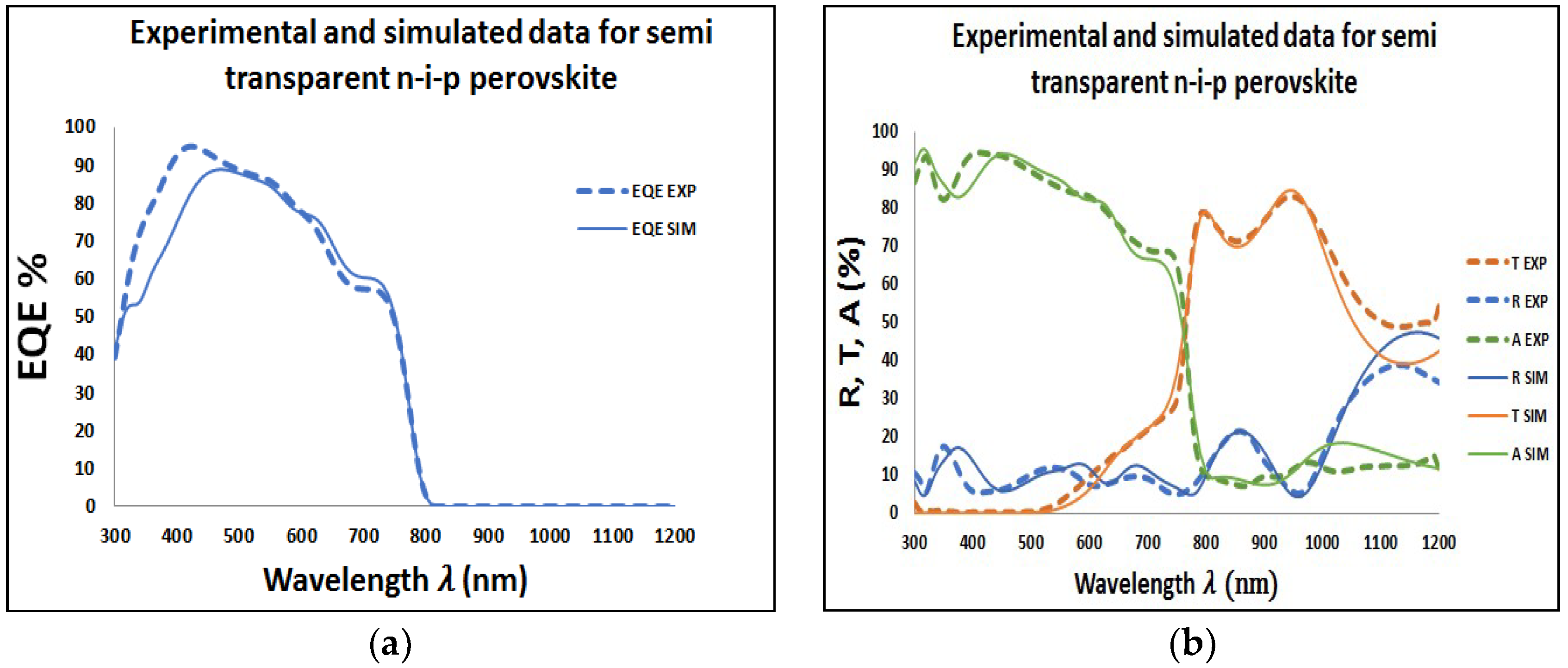
To investigate the effect of both Au and Ag NPs on the performance of the perovskite solar cell, the Au and Ag NPs were applied at the rear side of the perovskite solar cell with diameter above 40 nm. Then, we can obtain plasmonic resonance wavelength above 550 nm, which can compensate the external quantum efficiency losses in perovskite in this range of spectrum. Then, the Transfer-Matrix-Based Optical Simulation Method (TMM) was used in our investigation. This method allows modeling of the optical properties of thin-film layer stacks by solving Maxwell’s equations at each interface through using the complex refractive index and layer thicknesses of all relevant materials as input [35,36,37,38]. Reflectance (R), Transmittance (T), Absorbance (A), and EQE spectra of the fabricated perovskite solar cell were measured in order to calibrate and underline the accuracy of our optical simulations. More information on the calibration of the TMM optical simulator and the details of the perovskite solar cell fabrication process can be reviewed from our references [39,40]. Surface roughness is considered as an effective medium according to the Bruggeman effective medium approximation (BEMA) [41]. Therefore, in our simulations, interface roughness is simulated using a BEMA layer consisting of a mixture of the optical constants for the adjacent media. The accuracy of our optical simulation is confirmed by showing excellent agreement with experimental data, as shown in Figure 2a,b. However, small offsets between experimental and simulation data for long wavelengths in our transmission and reflection plots can be explained by absorption and/or scattering in the substrate.
The model used to describe the permittivity of gold and silver is Drude-critical points model. The model can be given in Equation (1) as follows [42]
where is the permittivity due to interband transitions, is the plasma frequency, is the damping constant. , , , and are constants and are summarized in Table 1 for gold and silver. The experimental data was taken from reference [43]. The model is valid for wavelengths in the range between 200 nm and 1000 nm [42]. The damping constant, counts for absorption loss is size dependent and given by Equation (2) [44,45,46]
where equals 1.0805 × 10¹⁴ rad/s and 4.5841 × 10¹³ rad/s for gold and silver respectively. The constant C is considered 1 for both of them [46], is the Fermi velocity and equals 1.39 × 10⁶ m/s and 1.38 × 10⁶ m/s for gold and silver, respectively, and R is the radius of the spherical NPs [45,46]. The refractive index is complex and simply expressed as follows in Equation (3)
The real and imaginary parts were calculated for both Au and Ag to be used in the simulation part. To calculate the absorption, scattering, and extinction cross sections of noble NPs, Mie theory can be used. Mie theory is using Maxwell equations to calculate the fields in the vicinity of the nanoparticle. Equation (4) shows the cross sections which can be can be given as [47]
where , , and are the extinction, scattering, and absorption cross sections, respectively, n is the multipole order, k is the wave number. Equation (5) shows the Mie coefficients and , which are given by [47]
where , and are Riccarti –Bessel functions, while , and are their derivatives.m is the ration of the complex refractive indices of the nanoparticle and the suttrounding medium. x is given by where is the wavelength of the incident light.
3. Simulation Procedure
In order to investigate the effect of Au and Ag NPs on the performance of the perovskite solar cell, optical loss analysis was considered by varying the thickness of both Au and Ag films at the rear side of the perovskite solar cell in our TMM simulations and calculating both internal current densities losses (Jshort, Jmedium, Jlong), the external losses (Jescape-back, Jreflection), the average transmittance (800–1200 nm), and the Jsc in our perovskite solar cell. Here, we assume one homogeneous layer of NPs on the perovskite cell. Therefore, the thickness of the plasmonic layer is the same as the diameter of NPs. According to the limitations of the used coding we have assumed that Au and Ag NPs or even though the Au and Ag planar film is deposited as one layer over the perovskite with negligible grain boundaries problems that can be found in the real design.
The internal current losses are calculated using Equation (6) by integrating the area between the EQE and the absorbance curves over the AM1.5G solar spectrum for different wavelength regions corresponding to short (λ = 300–450 nm), medium (λ = 450–700 nm), and long (λ = 700–1000 nm) internal current losses. For the external current losses, however, we focused on both losses of Jescape,back and Jreflection. Regarding the Jescape-back external loss, the back side of the semi-transparent perovskite cell was considered where part of the long wavelength light is lost by transmission through the semi-transparent ITO-rear through the nanoparticle material. This external loss is calculated by integrating the transmission curve of the cell according to Equation (7). Moreover, at the device front, part of the light is lost due to external reflection. These reflection losses (Jreflection) are calculated by integrating the reflection spectrum of the front side of the cell according to Equation (8). Then, by using TMM method and Equation (9), Jsc for each specific nanoparticle thickness can be expressed as shown [48].
where q is the elementary charge, h is Planck’s constant, c is the speed of the light, λ is the wavelength, Φ(λ) is the AM1.5G solar spectrum, Tcell is the transmission of the cell, R is the reflection of the cell.
4. Results & Discussions
4.1. Plasmonic Resonances of Au and Ag NPs
The real and imaginary parts of Au and Ag NPs are shown in Figure 3. The radius of Ag or Au NPs is 50 nm. All the used parameters are summarized in Table below [36]. As noticed, the real part of Au and Ag permittivity is very close and negative for a wide range of wavelengths. The negative real refractive index is responsible for the appearance of resonance wavelength. The imaginary part is responsible for the absorption loss. As seen, the silver loss is less than the gold loss.
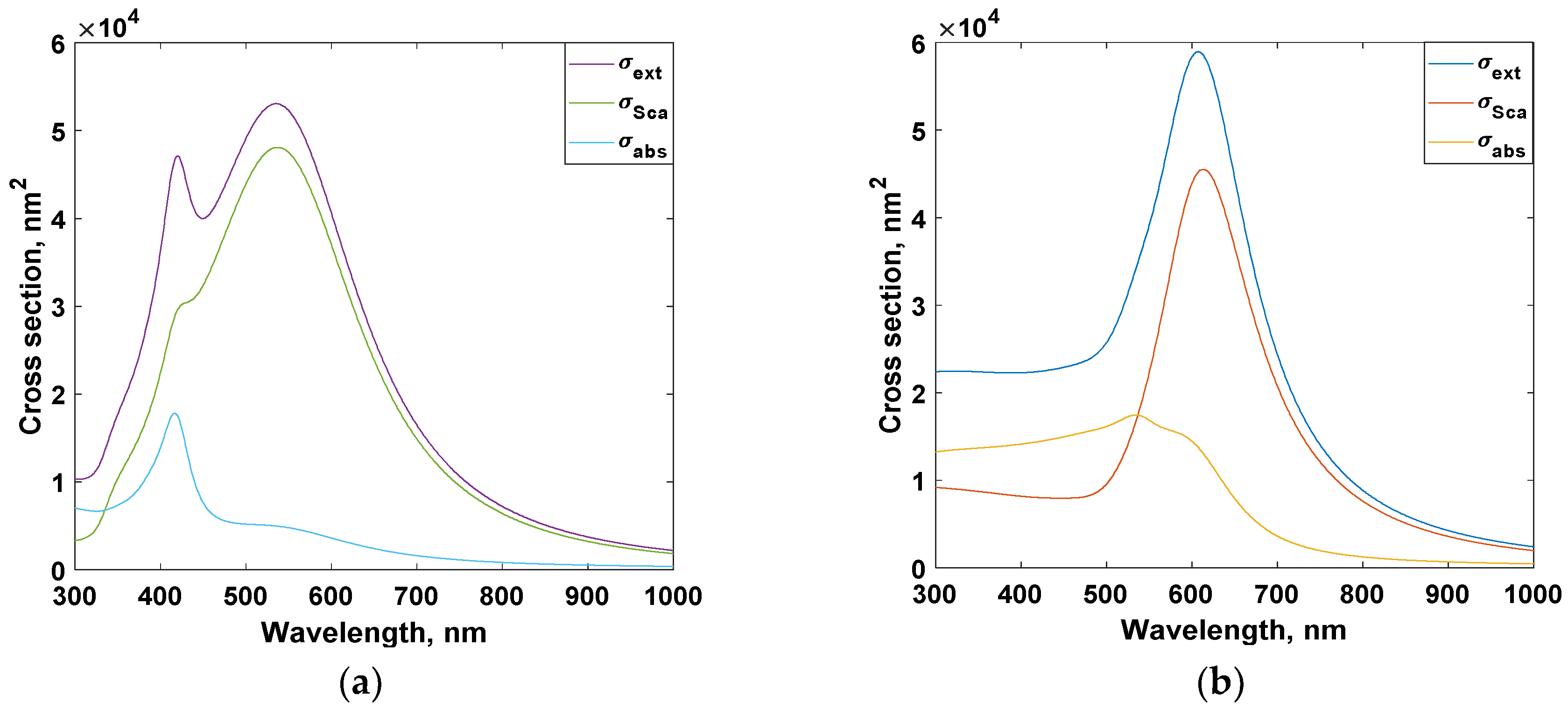
In Figure 4, the cross sections were simulated for particles of radius 50 nm. The surrounding medium has refractive index of value 1.5. For silver case, the cross section spectrum is much wide and may contain more than one peak. It is worthy to mention that, the resonance wavelength is size dependent. As the nanoparticle size increases, red shift occurs for Au and Ag cross sections.
4.2. Impact of Ag NPs on Perovskite Cells
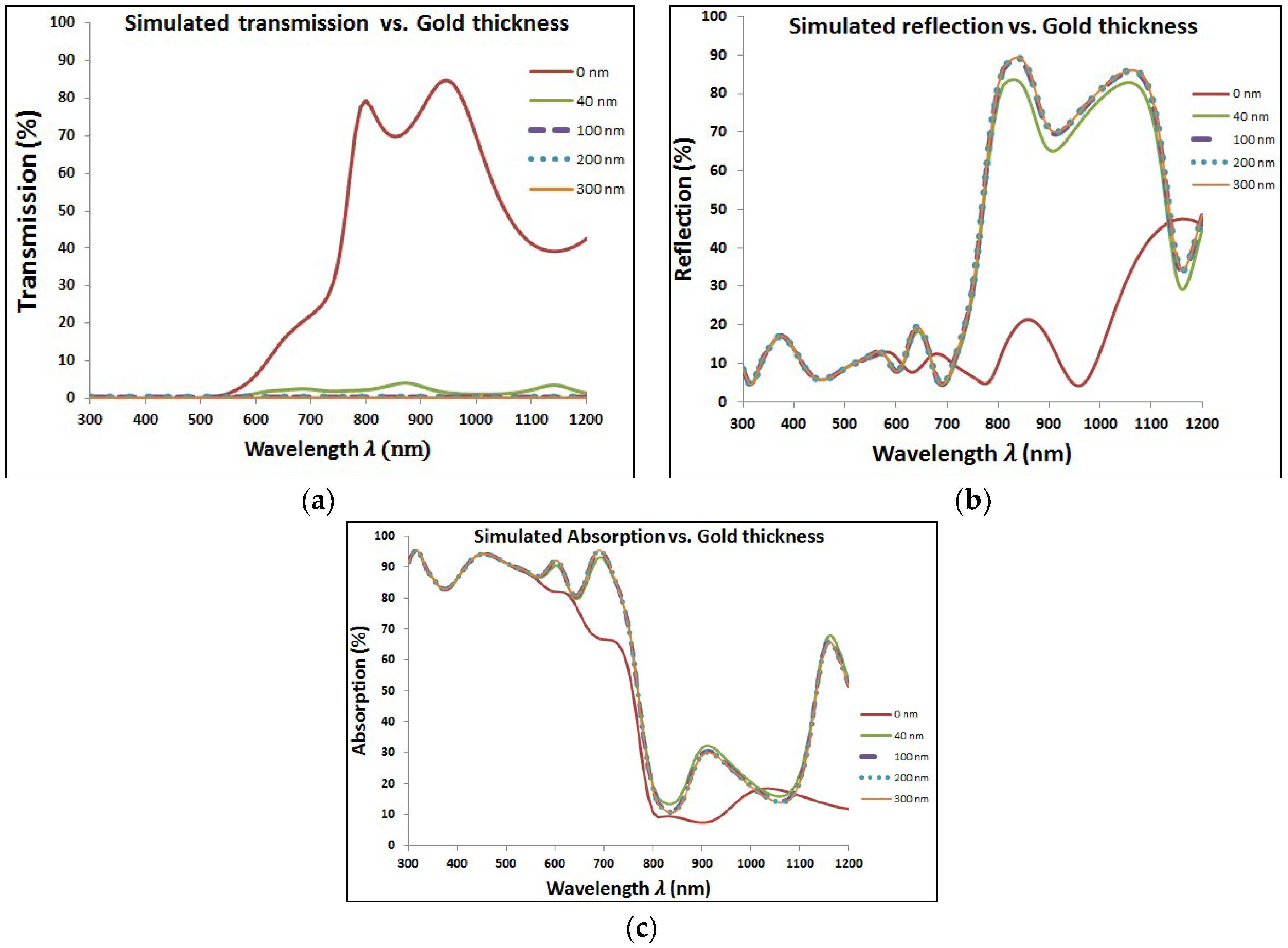
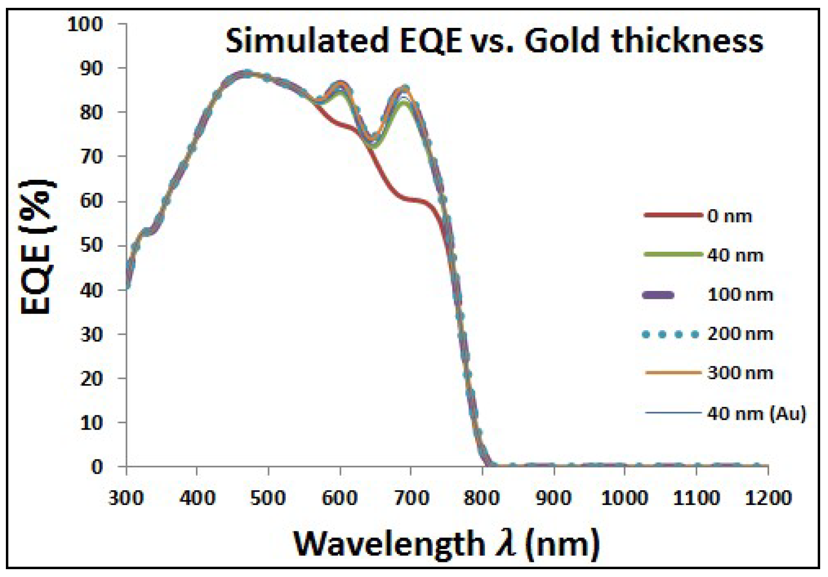
Figure 5 shows the optical characteristics of perovskite cell with added layer of Au NPs at different diameters. It can be noticed that the transmission is tremendously decreased with increasing the size of added Au NPs. However, the corresponding reflection and absorption have higher values with added Au NPs especially at wavelength around the plasmonic resonance wavelength. The resonance wavelength is varying from approximately ~550 to ~600 nm when the particle diameter is changing from 40 to 300 nm, respectively, for surrounding medium of refractive index of 1.5. Then, Figure 6 shows the improvement of EQE at wavelength range close to the plasmonic resonance frequency. The EQE enhancement can be explained due to the impact of reflected photoelectrons, which are trapped according to the added layer of plasmonic NPs, beside the optical enhancement of absorption due to plasmonic resonance of the added layer. There is a clear enhancement of EQE with lowest select size of Au NPs. By increasing Au NPs size, the EQE shows slight improvement with a saturation behavior at relatively higher NPs size up to 300 nm in diameter.
In Table 2, we compare the internal losses, external losses, and the corresponding Jsc of our solar cell with uniform NPs radii at different sizes to show its effect on our simulated perovskite solar cell. Simulations show a 1.24 mA/cm2 increase in the Jsc as a result of adding 40 nm Au NPs at the rear side of our perovskite solar cell. Further enhancement in Jsc is observed as the diameter of the Au NPs is increased beyond 40 nm. However, an insignificant difference in Jsc (≈0.1 mA/cm2) is observed when comparing the 40 nm Au NPs with a 40 nm Au planar thin film. The Au planar perovskite solar cell is displayed in order to better assess the performance of our Au NPs proposed solar cell structure. Furthermore, it can also be seen from the table a slight increase in the reflection loss as the thickness of the Au NPs at the rear side of the solar cell is increased. However, with increasing Au NPs thickness at the rear side of the perovskite solar cell, a noticeable decrease in the current loss due to transmission (Jescape,back) can be seen with nearly neglected value at 200 nm size or higher which shows a clear advantage of the added NPs.
4.3. Impact of Ag NPs on Perovskite Cells
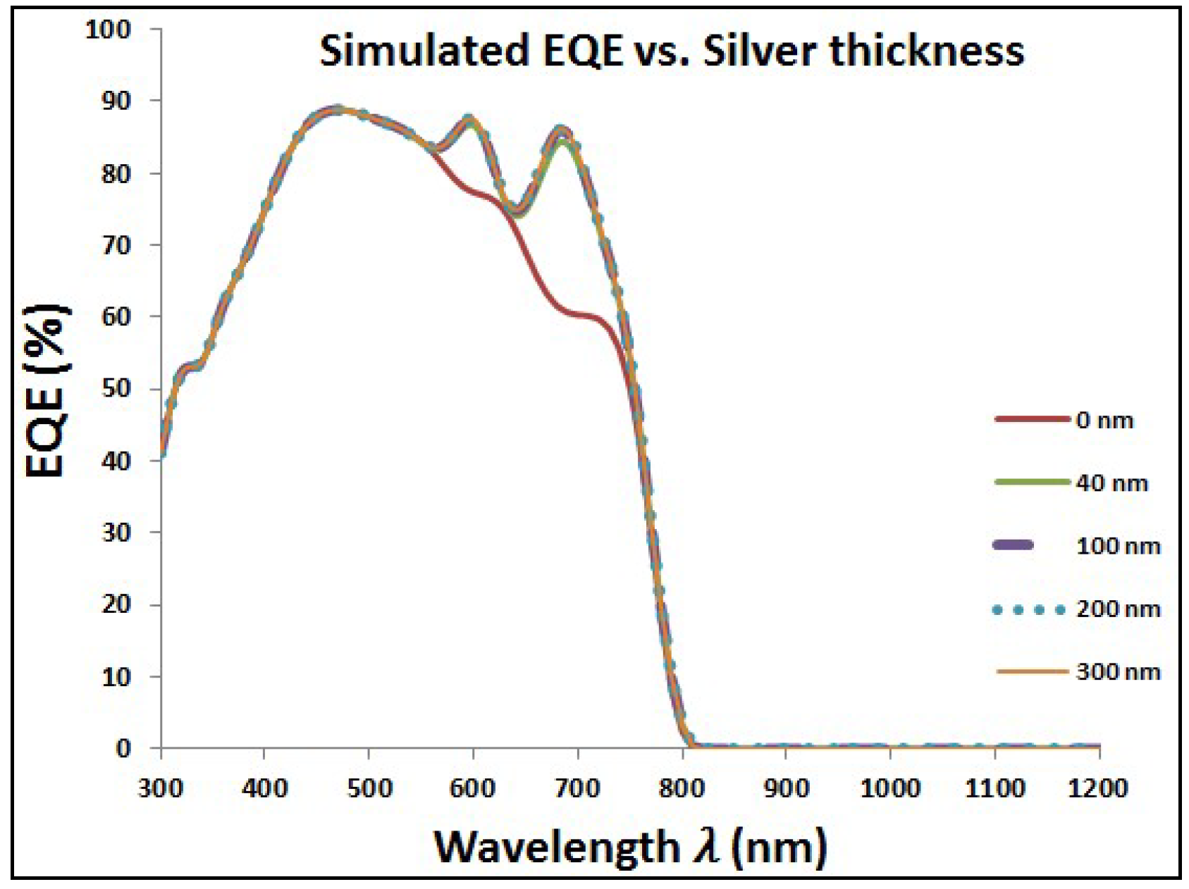
The same behavior of added Au NPs is repeated with another type of plasmonic nanostructure, which is silver. Figure 7 shows the optical characteristics of perovskite cell with added layer of Ag NPs at different diameters. As the case of gold, adding Ag NPs makes the transmission worse, but with improved reflection and absorption, especially at close wavelength-range to the plasmonic resonance of silver. The overall impact is the enhancement of EQE with added Ag NPs as shown in Figure 8. Table 3 shows the results of different types of current losses with different thickness of silver layer. Same behavior is existed as found in Table 1 in the case of Au NPs via enhancement of both reflection and short circuit currents. However, silver is showing higher enhancement in short circuit currents and faster decay of backside escape current with increasing the diameter of Ag NPs compared to gold.
4.4. Comparison Between Gold and Silver Effects
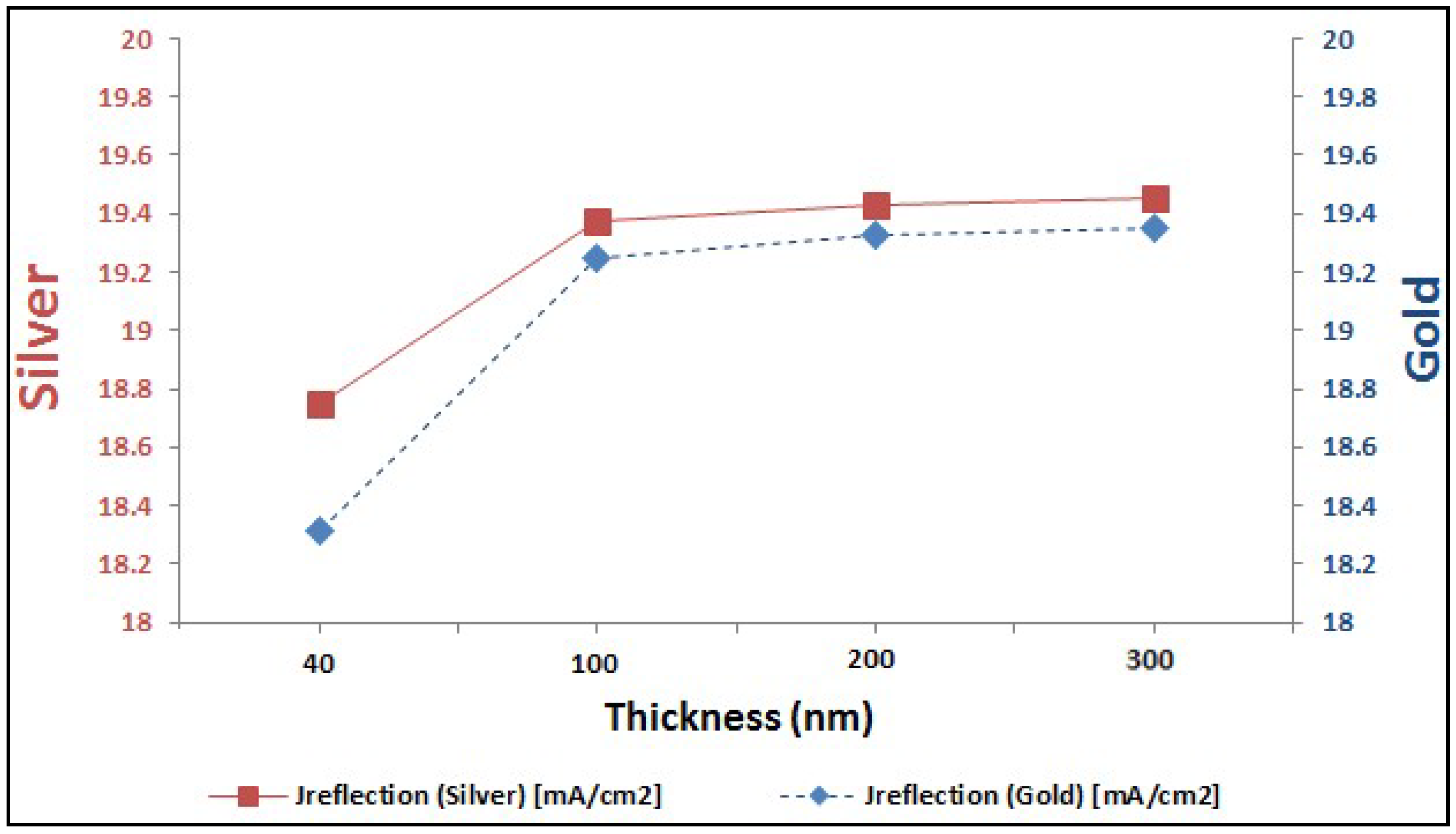
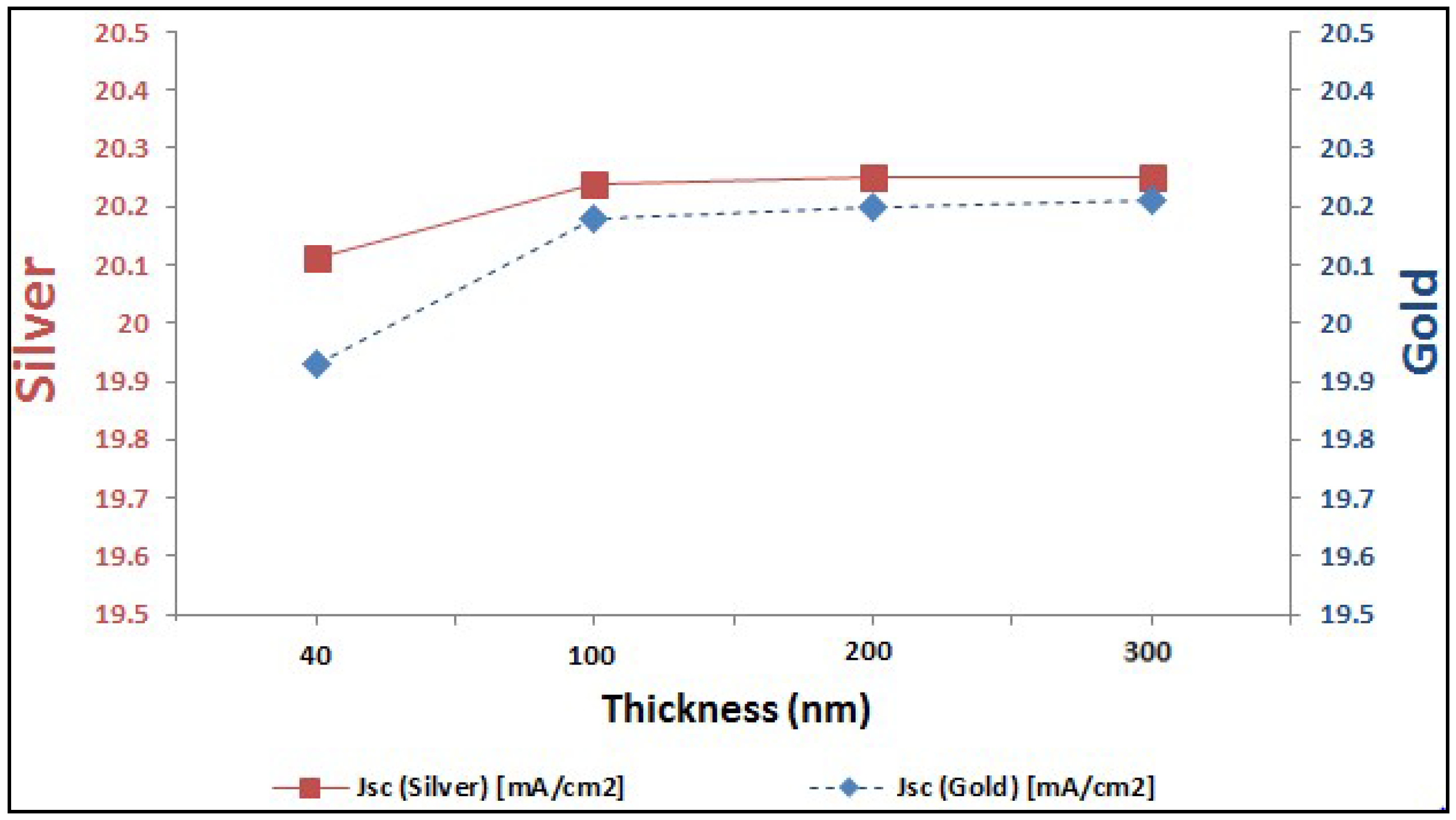
In last two sections, it is proved the enhancement of EQE of perovskite solar cells with added plasmonic NPs. Here, we are going to compare between both added plasmonic Au and Ag NPs. It can be shown from Figure 9 that Ag NPs enhance the EQE of perovskite cell slightly more than the added gold for different thicknesses of plasmonic layer. It can be explained through the better reflection capability that silver can offer compared to gold, as shown in Figure 10. This consequently leads to higher enhancement of short-circuit current in the case of silver compared to gold, as shown in the comparison figure at different layer thicknesses in Figure 11.
5. Outlook
To fully benefit from the plasmonic effects of adding Au or Ag NPs at the rear-side of perovskite solar cells, the existing key optical losses need to be identified and addressed. These optical losses can be attributed to: a) overall reflection b) free carrier absorption in ITO electrodes, c) parasitic losses due to absorption in the substrate and diffuse scattering. To minimize the loss due to reflection, anti-reflective coating (ARC) or nanophotonic transparent electrodes can be used to improve the overall Power Conversion Efficiency (PCE) of the solar cell [49]. Furthermore, novel high-mobility Transparent Conducting Oxides (TCOs) such as hydrogenated indium oxide exhibit lower free carrier densities than the commonly used Indium Tin Oxide (ITO), hence offering the chance to minimize the parasitic absorption in ITO electrode at the front side [50,51]. Moreover, to completely mitigate the parasitic losses due to absorption in the substrate and diffuse scattering, ultra smooth CH3NH3PbI3 films and non-absorbing substrates need to be used. More advanced light management concepts, trapping textures, and the optimization of the bandgap of the perovskite bear the potential to lead to very significant further improvements in light harvesting and current generation [52].
6. Conclusions
In this paper, the effect of adding plasmonic layer of Au and Ag NPs to the rear side of the perovskites solar cell is analytically studied. The resonance wavelength of the plasmonic NPs is adjusted to enhance the optical absorption of the solar cell in the visible range especially around the red wavelength. Both gold and silver lead to a promising enhancement in Jsc when the nanoparticle size becomes larger than 40 nm. Overall EQE enhancement is achieved. EQE improvement is slightly higher in case of adding silver compared to added gold.
Author Contributions
A.H. was responsible for simulations and analysis of perovskite solar cells. I.K. was responsible for simulation of the optical characteristics of gold and silver nanoparticles. N.S. had the main idea of the paper and helped in the analysis and explanation of the results of solar cells simulation.
Funding
The project was funded “partially” by Kuwait Foundation for the Advancement of Sciences under project code: P115-15EE-01.
Acknowledgments
The authors gratefully acknowledge the technical support of IMEC’s Industrial Affiliation Program for Photovoltaics (IIAP-PV) for providing the measurements on the fabricated perovskite solar cell.
Conflicts of Interest
The authors declare no conflict of interest.
References
- Kojima, A.; Teshima, K.; Shirai, Y.; Miyasaka, T. Organometal Halide Perovskites as Visible-Light Sensitizers for Photovoltaic Cells. J. Am. Chem. Soc. 2009, 131, 6050–6051. [Google Scholar] [CrossRef] [PubMed]
- Contreras, M.A.; Mansfield, L.M.; Egaas, B.; Li, J.; Romero, M.; Noufi, R.; Rudiger-voigt, E.; Mannstadt, W. Wide bandgap Cu(In,Ga)Se2 solar cells with improved energy conversion efficiency. Prog. Photovolt. Res. Appl. 2007, 15, 659. [Google Scholar]
- Burschka, J.; Pellet, N.; Moon, S.; Humphry-Baker, R.; Gao, P.; Nazeeruddin, M.; Grätzel, M. Sequential deposition as a route to high-performance perovskite-sensitized solar cells. Nature 2013, 499, 316–319. [Google Scholar] [CrossRef] [PubMed]
- Liu, M.; Johnston, M.B.; Snaith, H. Efficient planar heterojunction perovskite solar cells by vapour deposition. Nature 2013, 501, 395–398. [Google Scholar] [CrossRef] [PubMed]
- Chen, Q.; Zhou, H.; Hong, Z.; Luo, S.; Duan, H.; Wang, H.; Liu, Y.; Li, G.; Yang, Y. Planar heterojunction perovskite solar cells via vapor-assisted solution process. J. Am. Chem. Soc. 2013, 136, 622–625. [Google Scholar] [CrossRef] [PubMed]
- Umebayashi, T.; Asai, K.; Kondo, T.; Nakao, A. Electronic structures of lead iodide based low-dimensional crystals. Phys. Rev. B 2003, 67, 155405. [Google Scholar] [CrossRef]
- Snaith, H. Perovskites: The Emergence of a New Era for Low-Cost, High-Efficiency Solar Cells. J. Phys. Chem. Lett. 2013, 4, 3623. [Google Scholar] [CrossRef]
- Noh, J.H.; Im, S.H.; Heo, J.H.; Mandal, T.N.; Seok, S.I. Chemical management for colorful, efficient, and stable inorganic-organic hybrid nanostructured solar cells. Nano Lett. 2013, 13, 1764–1769. [Google Scholar] [CrossRef] [PubMed]
- Stoumpos, C.C.; Malliakas, C.D.; Kanatzidis, M.G. Semiconducting Tin and Lead Iodide Perovskites with Organic Cations: Phase Transitions, High Mobilities, and Near-Infrared Photoluminescent Properties. Inorg. Chem. 2013, 52, 9019–9038. [Google Scholar] [CrossRef] [PubMed]
- De Wolf, S.; Holovsky, J.; Moon, S.J.; Löper, P.; Niesen, B.; Ledinsky, M.; Haug, F.; Yum, J.H.; Ballif, C. Organometallic Halide Perovskites: Sharp Optical Absorption Edge and Its Relation to Photovoltaic Performance. J. Phys. Chem. Lett. 2014, 5, 1035. [Google Scholar] [CrossRef] [PubMed]
- Löper, P.; Stuckelberger, M.; Niesen, B.; Werner, J.; Filipic, M.; Moon, S.J.; Yum, J.H.; Topic, M.; De Wolf, S.; Ballif, C. Complex Refractive Index Spectra of CH3NH3PbI3 Perovskite Thin Films Determined by Spectroscopic Ellipsometry and Spectrophotometry. J. Phys. Chem. Lett. 2015, 6, 66. [Google Scholar] [CrossRef] [PubMed]
- Yin, W.J.; Shi, T.; Yan, Y. Unusual defect physics in CH3NH3PbI3 perovskite solar cell absorber. Appl. Phys. Lett. 2014, 104, 063903. [Google Scholar] [CrossRef]
- Xing, G.; Mathews, N.; Lim, S.; Lam, Y.; Mhaisalkar, S.; Sum, T.C. Long-range balanced electron- and hole-transport lengths in organic-inorganic CH3NH3PbI3. Science 2013, 6960, 498. [Google Scholar] [CrossRef] [PubMed]
- Stranks, S.; Eperon, G.; Grancini, G.; Menelaou, C.; Alcocer, M.; Leijtens, T.; Herz, L.; Petrozza, A.; Snaith, H. Electron-hole diffusion lengths exceeding 1 micrometer in an organometal trihalide perovskite absorber. Science 2014, 342, 341. [Google Scholar] [CrossRef] [PubMed]
- Gonzalez-Pedro, V.; Juarez-Perez, E.; Arsyad, W.; Barea, E.; Fabregat-Santiago, F.; Mora-Sero, I.; Bisquert, J. General working principles of CH3NH3PbX3 perovskite solar cells. Nano Lett. 2014, 14, 888–893. [Google Scholar] [CrossRef] [PubMed]
- Krishnan, A.; Das, S.; Krishna, S.; Khan, M. Multilayer nanoparticle arrays for broad spectrum absorption enhancement in thin film solar cells. Opt. Express 2014, 22, A800–A811. [Google Scholar] [CrossRef] [PubMed]
- Mendes, M.; Morawiec, S.; Simone, F.; Priolo, F.; Crupi, I. Colloidal plasmonic back reflectors for light trapping in solar cells. Nanoscale 2014, 6, 4796–4805. [Google Scholar] [CrossRef] [PubMed] [Green Version]
- Dabirian, A.; Byranv, M.; Naqavi, A.; Kharat, A.; Taghavinia, N. Theoretical Study of Light Trapping in Nanostructured Thin Film Solar Cells Using Wavelength-Scale Silver Particles. ACS Appl. Mater. Interfaces 2016, 8, 247–255. [Google Scholar] [CrossRef] [PubMed]
- Pillai, S.; Catchpole, K.; Trupke, T.; Green, M. Surface plasmon enhanced silicon solar cells. J. Appl. Phys. 2007, 101, 093105. [Google Scholar] [CrossRef]
- Sannomiya, T.; Voros, J. Single plasmonic nanoparticles for biosensing. Trends Biotechnol. 2011, 29, 343–351. [Google Scholar] [CrossRef] [PubMed]
- Zeng, S.; Yong, K.; Roy, I.; Dinh, X.; Yu, X.; Luan, F. A Review on Functionalized Gold Nanoparticles for Biosensing Applications. Plasmonics 2011, 6, 491–506. [Google Scholar] [CrossRef]
- Sepulveda, B.; Angelome, P.; Lechuga, L.; Liz-Marzan, L. LSPR-based nanobiosensors. Nano Today 2009, 4, 244–251. [Google Scholar] [CrossRef]
- Proise, F.; Joudrier, A.; Pardo, F.; Pelouard, J.; Guillemoles, J. Ultrathin mono-resonant nano photovoltaic device for broadband solar conversion. Opt. Express 2018, 26, A806. [Google Scholar] [CrossRef]
- Atwater, H.; Polman, A. Plasmonics for improved photovoltaic devices. Nat. Mater. 2010, 9, 865. [Google Scholar] [CrossRef]
- Beck, F.; Mokkapati, S.; Catchpole, K. Light trapping with plasmonic particles: beyond the dipole model. Opt. Express 2011, 19, 25230–25241. [Google Scholar] [CrossRef] [PubMed]
- Saleh, Z.; Nasser, H.; Özkol, E.; Günöven, M.; Altuntas, B.; Bek, A.; Turan, R. Enhanced Optical Absorption and Spectral Photocurrent in a-Si: H by Single- and Double-Layer Silver Plasmonic Interfaces. Plasmonics 2014, 9, 357–365. [Google Scholar] [CrossRef]
- Carretero-Palacios, S.; Jiménez-Solano, A.; Míguez, H. Plasmonic Nanoparticles as Light-Harvesting Enhancers in Perovskite Solar Cells: A User’s Guide. ACS Energy Lett. 2016, 1, 323–331. [Google Scholar] [CrossRef] [PubMed]
- Batmunkh, M.; Macdonald, T.; Peveler, W.; Bati, A.; Carmalt, C.; Parkin, I.; Shapter, J. Plasmonic Gold Nanostars Incorporated into High- Efficiency Perovskite Solar Cells. ChemSusChem 2017, 10, 3750–3753. [Google Scholar] [CrossRef] [PubMed]
- Macdonald, T.; Ambroz, F.; Batmunkh, M.; Li, Y.; Kim, D.; Contini, C.; Poduval, R.; Liu, H.; Shapter, J.; Papakonstantinou, I.; et al. TiO2 nanofiber photoelectrochemical cells loaded with sub-12 nm AuNPs: Size dependent performance evaluation. Mater. Today Energy 2018, 9, 254–263. [Google Scholar] [CrossRef]
- Derkachova, A.; Kolwas, K.; Demchenko, I. Dielectric Function for Gold in Plasmonics Applications: Size Dependence of Plasmon Resonance Frequencies and Damping Rates for Nanospheres. Plasmonics 2016, 11, 941–951. [Google Scholar] [CrossRef] [PubMed]
- Catchpole, K.; Polman, A. Design principles for particle plasmon enhanced solar cells. Appl. Phys. Lett. 2008, 93, 191113. [Google Scholar] [CrossRef]
- Catchpole, K.; Polman, A. Plasmonic solar cells. Opt. Express 2008, 16, 21793–21800. [Google Scholar] [CrossRef] [PubMed]
- Pillai, S.; Green, M. Plasmonics For Photovoltaic Applications. Sol. Energy Mater. Sol. Cells 2010, 94, 1481–1486. [Google Scholar] [CrossRef]
- Zhu, J.; Xue, M.; Hoekstra, R.; Xiu, F.; Zeng, B.; Wang, K.L. Light concentration and redistribution in polymer solar cells by plasmonic nanoparticles. Nanoscale 2012, 4, 1978–1981. [Google Scholar] [CrossRef] [PubMed]
- Anaya, M.; Lozano, G.; Calvo, M.; Zhang, W.; Johnston, M.; Snaith, H. Optical Description of Mesostructured Organic-Inorganic Halide Perovskite Solar Cells. J. Phys. Chem. Lett. 2015, 6, 48. [Google Scholar] [CrossRef] [PubMed]
- Yang, D.; Yang, R.; Wang, K.; Wu, C.; Zhu, X.; Feng, J.; Ren, X.; Fang, G.; Priya, S.; Liu, S.F. High efficiency planar-type perovskite solar cells with negligible hysteresis using EDTA-complexed SnO2. Nat. Commun. 2018, 9, 3239. [Google Scholar] [CrossRef] [PubMed]
- Correa-Baena, J.; Anaya, M.; Lozano, G.; Tress, W.; Domanski, K.; Saliba, M.; Matsui, T.; Jacobsson, T.; Calvo, M.; Abate, A.; et al. Unbroken Perovskite: Interplay of Morphology, Electro-optical Properties, and Ionic Movement. Adv. Mater. 2016, 1, 5031. [Google Scholar] [CrossRef] [PubMed]
- Paetzold, U.; Qiu, W.; Finger, F.; Poortmans, J.; Cheyns, D. Nanophotonic front electrodes for perovskite solar cells. Appl. Phys. Lett. 2015, 106, 173101. [Google Scholar] [CrossRef]
- Eerden, M.; Jaysankar, M.; Hadipour, A.; Merckx, T.; Schermer, J.; Aernouts, T.; Poortmans, J.; Paetzold, U. Optical Analysis of Planar Multicrystalline Perovskite Solar Cells. Adv. Opt. Mater. 2017, 5, 1700151. [Google Scholar] [CrossRef]
- Paetzold, U.W.; Gehlhaar, R.; Tait, J.; Qiu, W.; Bastos, J.; Debucquoy, M.; Poortmans, J. Optical loss analyses and energy yield modelling of perovskite/silicon multijunction solar cells. Opt. Soc. Am. 2016, SoW2C-4. [Google Scholar] [CrossRef]
- Bruggeman, D. Calculation of various physical constants of heterogeneous substances. I. dielectric constant and conductivity of the mixing body made of isotropic substances. Ann. Phys. 1935, 416, 636. [Google Scholar] [CrossRef]
- Vial, A.; ·Laroche, T. Comparison of gold and silver dispersion laws suitable for FDTD simulations. Appl. Phys. B 2008, 93, 139–143. [Google Scholar] [CrossRef]
- Johnson, P.B.; Christy, R.W. Optical Constants of the Noble Metals. Phys. Rev. B 1972, 6, 4370. [Google Scholar] [CrossRef]
- Carminati, R.; Greffet, J.; Henkel, C.; Vigoureux, J. Radiative and non-radiative decay of a single molecule close to a metallic nanoparticles. Opt. Commun. 2006, 261, 368–375. [Google Scholar] [CrossRef]
- Myroshnychenko, V.; Rodrıiguez-Fernandez, J.; Pastoriza-Santos, I.; Funston, A.; Novo, C.; Mulvaney, P.; Liz-Marzan, L.; Javier Garcıa de Abajo, F. Modelling the optical response of gold nanoparticles. Chem. Soc. Rev. 2008, 37, 1792–1805. [Google Scholar] [CrossRef] [PubMed]
- Chung, H.; Leung, P.; Tsai1, D. Molecular fluorescence in the vicinity of a charged metallic nanoparticles. Opt. Express 2013, 22, 26483–26492. [Google Scholar] [CrossRef] [PubMed]
- Craig, F.; Bohren, F.; Huffman, D. Absorption and Scattering of Light by Small Particles; John Wiley & Sons: New York, NY, USA, 1983. [Google Scholar]
- Paviet-Salomon, B.; Tomasi, A.; Descoeudres, A.; Barraud, L.; Nicolay, S.; Despeisse, A.; De Wolf, S.; Ballif, C. Back-Contacted Silicon Heterojunction Solar Cells: Optical-Loss Analysis and Mitigation. IEEE J. Photovolt. 2015, 5, 1293–1303. [Google Scholar] [CrossRef] [Green Version]
- Bailie, C.; Christoforo, M.; Mailoa, J.; Bowring, A.; Unger, E.; Nguyen, W.; Burschka, J.; Pellet, N.; Lee, J.; Grätzel, M.; et al. Semi-transparent perovskite solar cells for tandems with silicon and CIGS. Energy Environ. Sci. 2015, 8, 956. [Google Scholar] [CrossRef]
- Fu, F.; Feurer, T.; Jäger, T.; Avancini, E.; Bissig, B.; Yoon, S.; Buecheler, S.; Tiwari, A. Low-temperature-processed efficient semi-transparent planar perovskite solar cells for bifacial and tandem applications. Nat. Commun. 2015, 6, 8932. [Google Scholar] [CrossRef] [PubMed] [Green Version]
- Yin, G.; Steigert, A.; Manley, P.; Klenk, R.; Schmid, M. Enhanced absorption in tandem solar cells by applying hydrogenated In2O3 as electrode. Appl. Phys. Lett. 2015, 107, 211901. [Google Scholar] [CrossRef] [Green Version]
- La, N.; White, T.; Catchpole, K. Optics and Light Trapping for Tandem Solar Cells on Silicon. IEEE J. Photovolt. 2014, 4, 1380. [Google Scholar]
Figure 1.
Schematic model of the semi-transparent n-i-p CH3NH3PbI3 perovskite solar cells applied in the transfer-matrix-based optical simulations. The variable material layer is where gold and silver nanoparticles (Au and Ag NPs) are included in our simulations. Roughness is simulated as an effective medium of the adjacent media using the Bruggeman effective medium approximation.
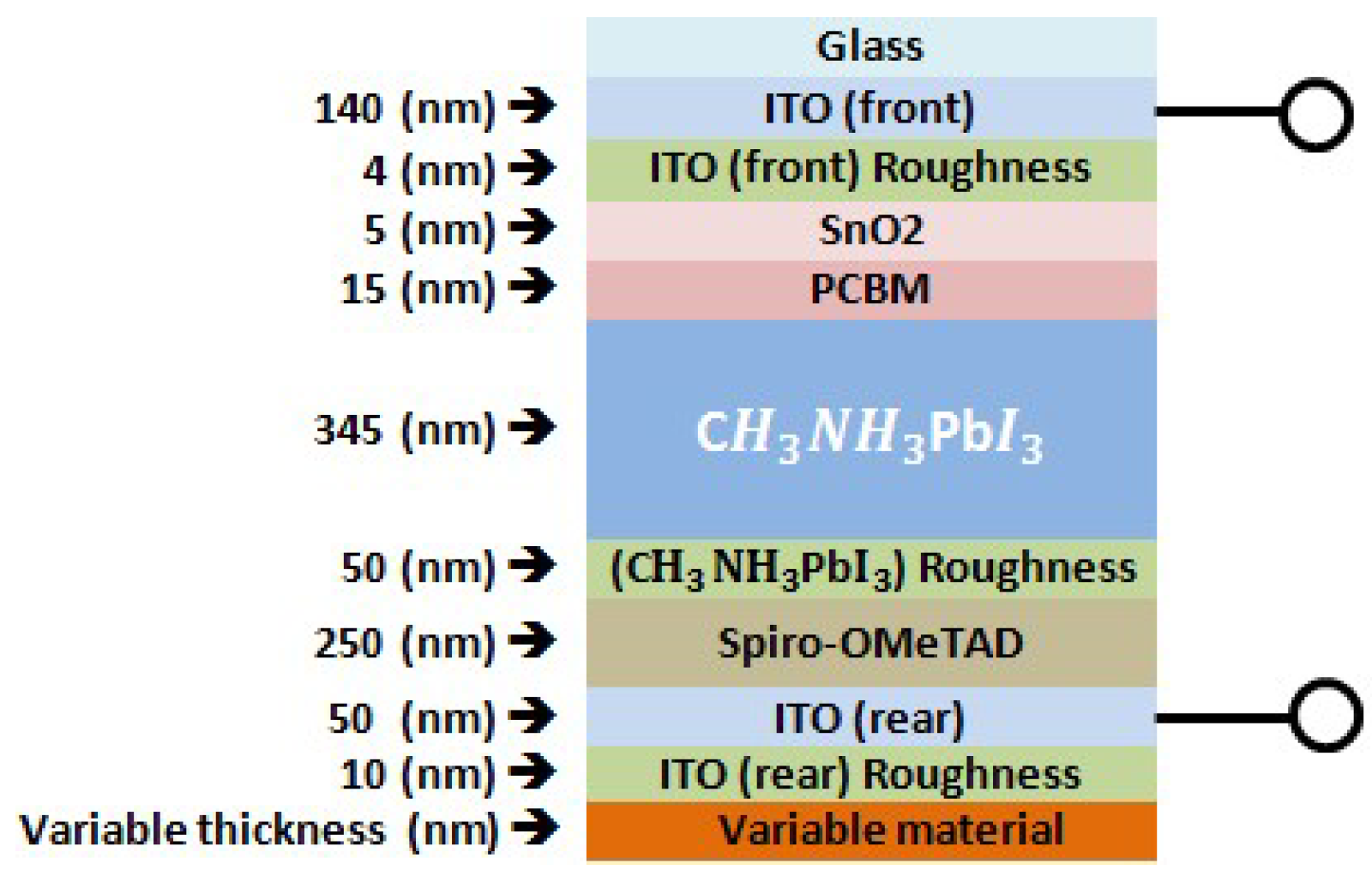
Figure 2.
(a) Shows measured and simulated external quantum efficiency (EQE)% and (b) shows measured and simulated percentages of reflectance, transmittance, and absorbance spectra of semitransparent CH3NH3PbI3 solar cell with the architecture glass/ITO-front/ITO-front-roughness/SnO2/PCBM/CH3NH3PbI3/CH3NH3PbI3-roughness/spiro-OMeTAD/ITO-rear/ITO-rear-roughness. The dotted line represents measurements on the actual device and solid line represents transfer-matrix-based simulations.

Figure 3.
Real and imaginary parts of Au and Ag permittivity.
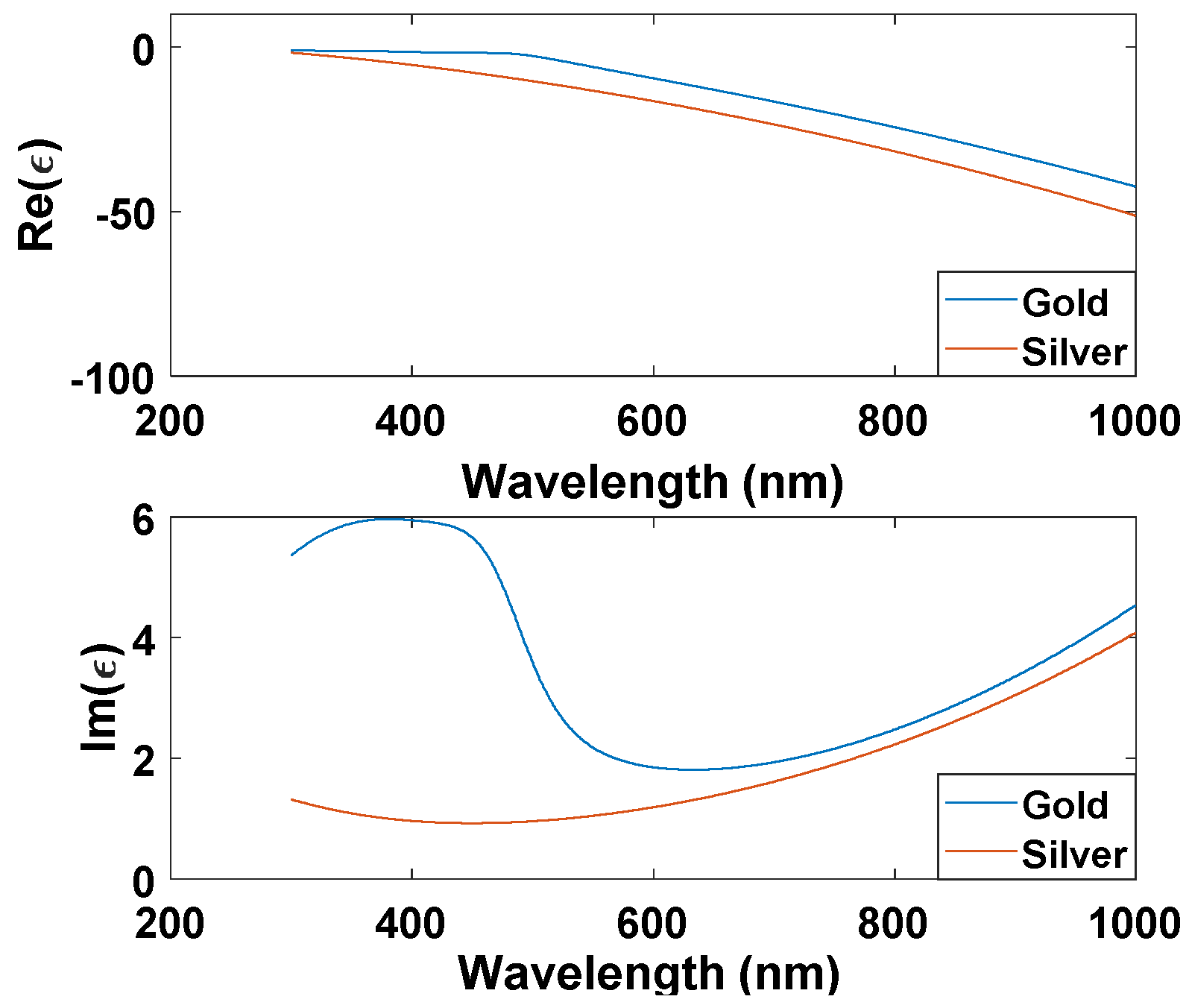
Figure 4.
Cross sections of (a) Au, and (b) Ag plasmonic nanoparticles (NPs).

Figure 5.
Optical characteristics for perovskite cell with different thickness of gold layer. These characteristics are (a) Transmission, (b) Reflection, and (c) Absorption.
Figure 5.
Optical characteristics for perovskite cell with different thickness of gold layer. These characteristics are (a) Transmission, (b) Reflection, and (c) Absorption.

Figure 6.
Enhancement of external quantum efficiency (EQE) due to added gold nanoparticles (Au NPs) in the wavelength range close to plasmonic resonance of gold.
Figure 6.
Enhancement of external quantum efficiency (EQE) due to added gold nanoparticles (Au NPs) in the wavelength range close to plasmonic resonance of gold.

Figure 7.
Optical characteristics for perovskite cell with different thicknesses of silver layer.
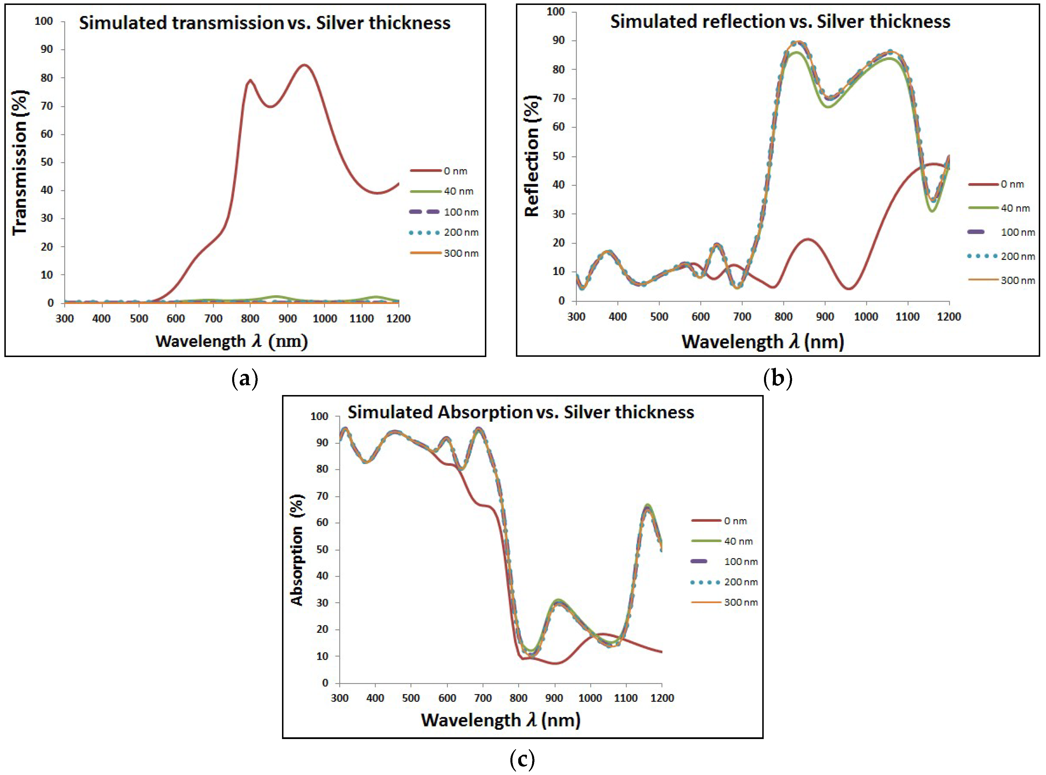
Figure 8.
Enhancement of external quantum efficiency (EQE) due to added silver nanoparticles (Ag NPs) in the wavelength range close to plasmonic resonance of silver.
Figure 8.
Enhancement of external quantum efficiency (EQE) due to added silver nanoparticles (Ag NPs) in the wavelength range close to plasmonic resonance of silver.

Figure 9.
Comparison of external quantum efficiency (EQE) curves at added Au and Ag at different size of nanoparticles (NPs).
Figure 9.
Comparison of external quantum efficiency (EQE) curves at added Au and Ag at different size of nanoparticles (NPs).

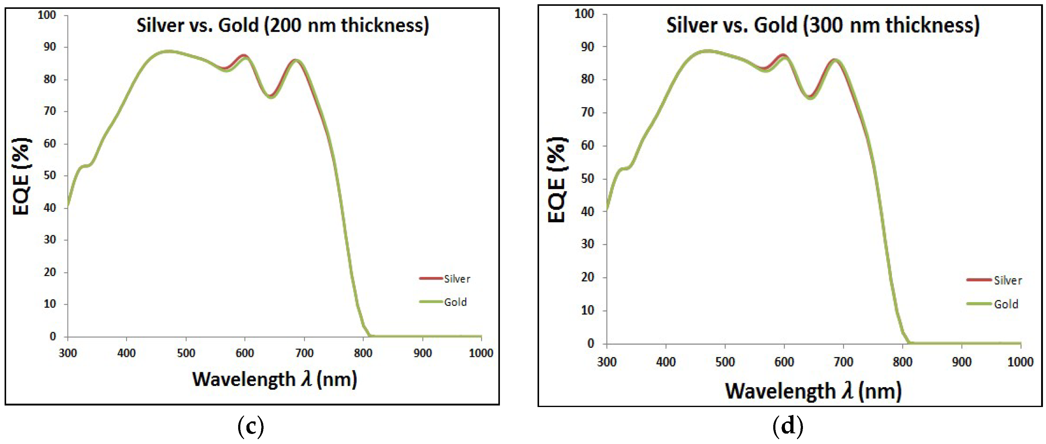
Figure 10.
Optical reflection due to Au and Ag at different size of nanoparticles (NPs).

Figure 11.
Comparison of Jsc values in the cell according to added Au and Ag at different size of nanoparticles (NPs).
Figure 11.
Comparison of Jsc values in the cell according to added Au and Ag at different size of nanoparticles (NPs).


Table 1.
Parameters used in Drude model.
| A1 | A2 | |||||||||
|---|---|---|---|---|---|---|---|---|---|---|
| Au | 1.1431 | 1.3202 × 10¹⁶ | 0.2669 | 3.0834 | −1.2371 | −1.0968 | 3.8711 × 10¹⁵ | 4.1684 × 10¹⁵ | 4.4642 × 10¹⁴ | 2.3555 × 10¹⁵ |
| Ag | 15.833 | 1.3861 × 10¹⁶ | 1.0171 | 15.797 | −0.9394 | 1.8087 | 6.6327 × 10¹⁵ | 9.2726 × 10¹⁷ | 1.6666 × 10¹⁵ | 2.3716 × 10¹⁷ |
Table 2.
The effect of added gold nanoparticles (Au NPs) of different nanosize on the internal losses, external losses, and the short circuit current for our simulated Perovskite solar cell.
Table 2.
The effect of added gold nanoparticles (Au NPs) of different nanosize on the internal losses, external losses, and the short circuit current for our simulated Perovskite solar cell.
| Perovskite Cell Losses (mA/cm2) | ||||
|---|---|---|---|---|
| Gold (nm) | ||||
| 0 | 4.15 | 16.49 | 6.55 | 18.69 |
| 40 (Au) planar | 6.939 | 0.784 | 18.7 | 20.03 |
| 40 (Au NPs) | 7.45 | 0.764 | 18.31 | 19.93 |
| 100 (Au NPs) | 7.013 | 0.009 | 19.25 | 20.18 |
| 200 (Au NPs) | 6.926 | 0.000 | 19.33 | 20.20 |
| 300 (Au NPs) | 6.899 | 0.000 | 19.35 | 20.21 |
Table 3.
The effect of added silver nanoparticles (Ag NPs) of different nanosize on the internal losses, external losses, and the short circuit current for our simulated Perovskite solar cell.
Table 3.
The effect of added silver nanoparticles (Ag NPs) of different nanosize on the internal losses, external losses, and the short circuit current for our simulated Perovskite solar cell.
| Perovskite Cell Losses (mA/cm2) | ||||
|---|---|---|---|---|
| Silver (nm) | ||||
| 0 | 4.15 | 16.49 | 6.55 | 18.69 |
| 40 | 7.182 | 0.41 | 18.75 | 20.11 |
| 100 | 6.846 | 0.002 | 19.37 | 20.24 |
| 200 | 6.778 | 0.000 | 19.43 | 20.25 |
| 300 | 6.756 | 0.000 | 19.45 | 20.25 |
© 2018 by the authors. Licensee MDPI, Basel, Switzerland. This article is an open access article distributed under the terms and conditions of the Creative Commons Attribution (CC BY) license (http://creativecommons.org/licenses/by/4.0/).
Share and Cite
MDPI and ACS Style
Hajjiah, A.; Kandas, I.; Shehata, N. Efficiency Enhancement of Perovskite Solar Cells with Plasmonic Nanoparticles: A Simulation Study. Materials 2018, 11, 1626. https://doi.org/10.3390/ma11091626
AMA Style
Hajjiah A, Kandas I, Shehata N. Efficiency Enhancement of Perovskite Solar Cells with Plasmonic Nanoparticles: A Simulation Study. Materials. 2018; 11(9):1626. https://doi.org/10.3390/ma11091626
Chicago/Turabian StyleHajjiah, Ali, Ishac Kandas, and Nader Shehata. 2018. "Efficiency Enhancement of Perovskite Solar Cells with Plasmonic Nanoparticles: A Simulation Study" Materials 11, no. 9: 1626. https://doi.org/10.3390/ma11091626
Note that from the first issue of 2016, this journal uses article numbers instead of page numbers. See further details here.