Wide-Band Circularly Polarized ReflectarrayUsing Graphene-Based Pancharatnam-Berry Phase Unit-Cells for Terahertz Communication


Abstract
1. Introduction
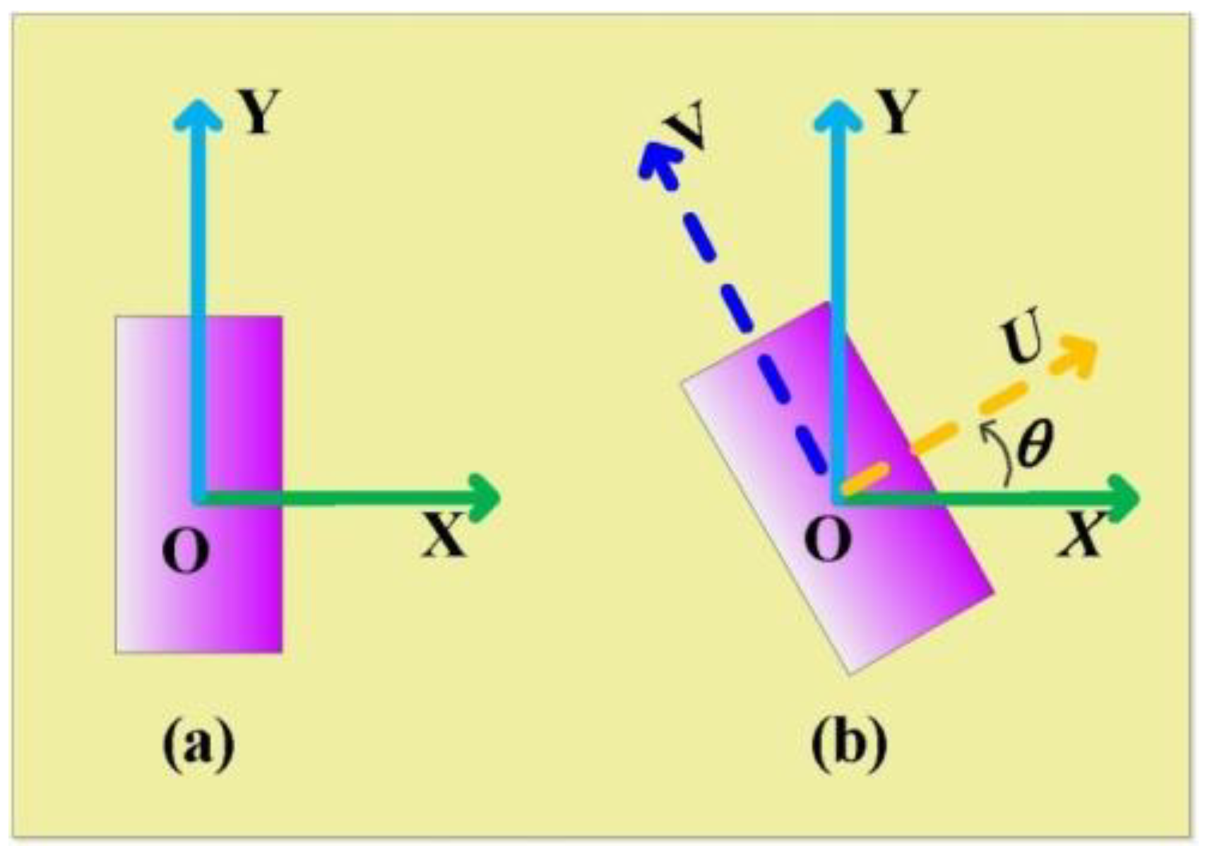
2. PB Principle
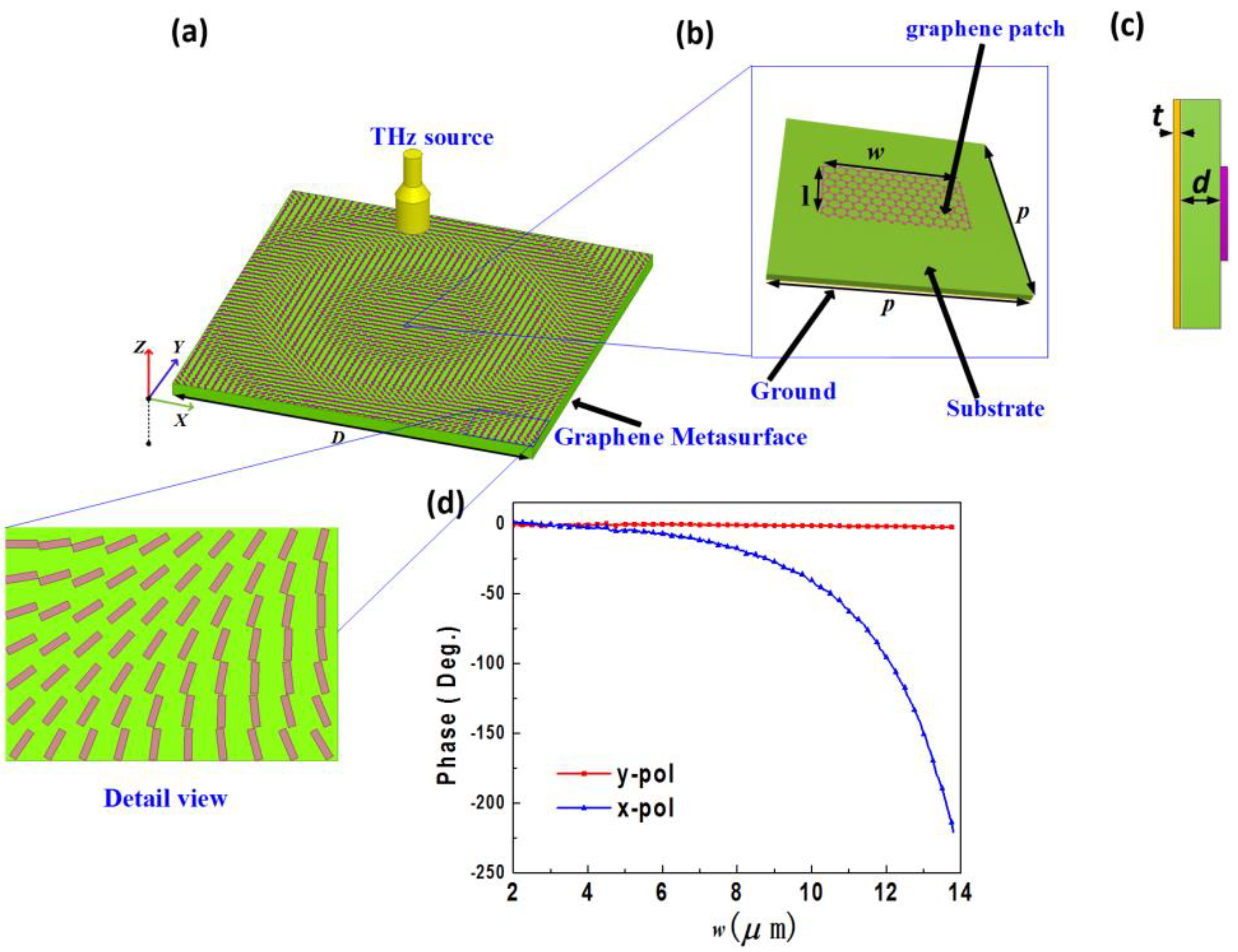
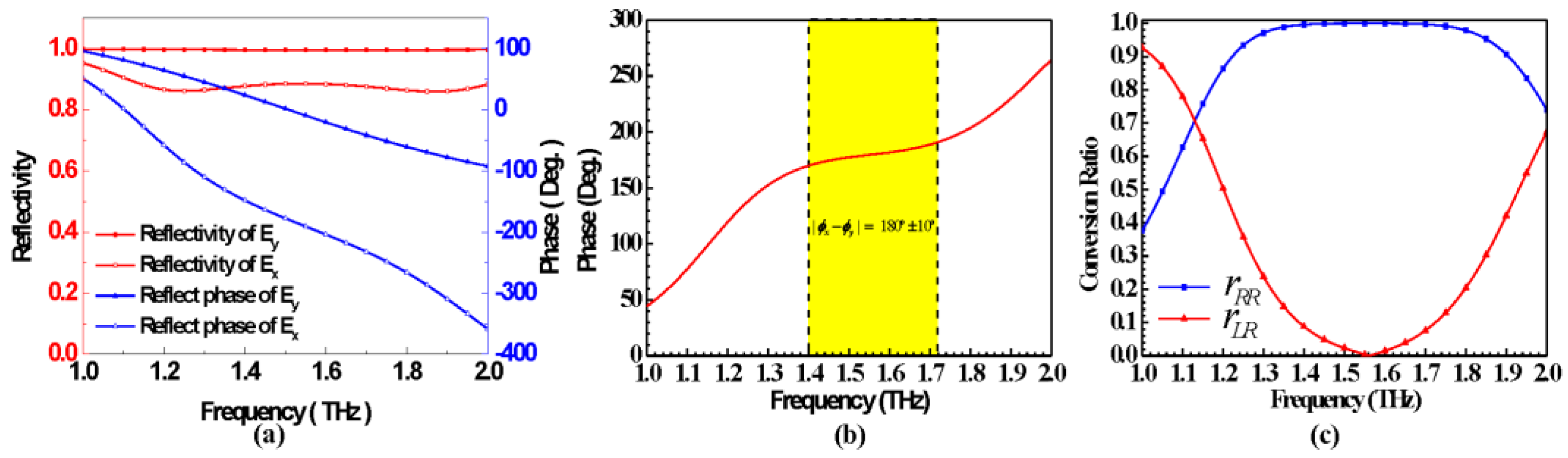
3. Graphene Based PB Unit-Cell
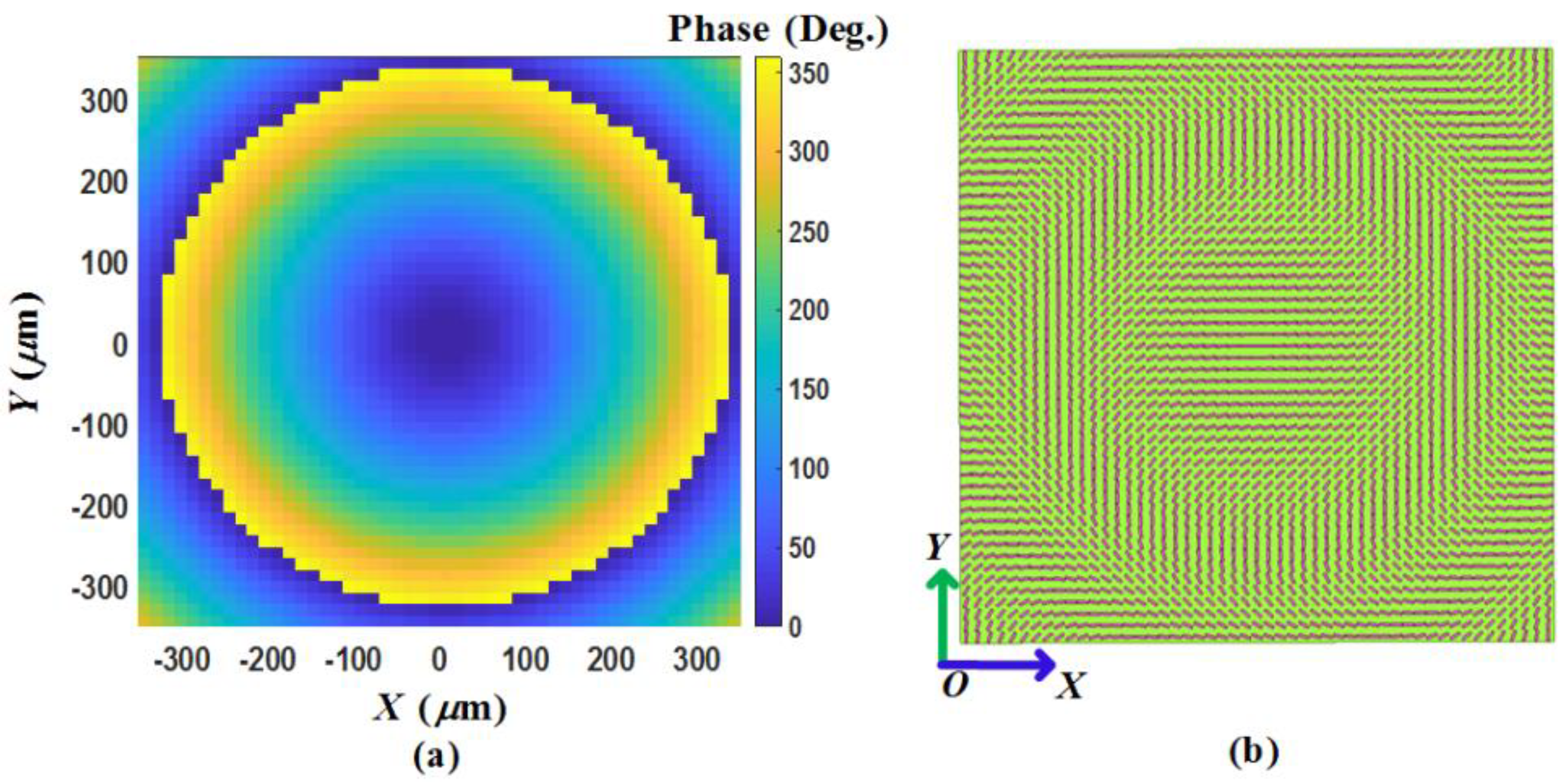
4. Graphene Metasurface for Focusing
5. High Gain CP Graphene-Based Reflectarray
6. Conclusions
Author Contributions
Funding
Conflicts of Interest
References
- Petrov, V.; Komarov, M.; Moltchanov, D.; Jornet, J.M.; Koucheryavy, Y. Interference and SINR in millimeter waveand terahertz communication systems with blocking and directional antennas. IEEE Trans. Wirel. Commun. 2017, 16, 1791–1808. [Google Scholar] [CrossRef]
- Singh, L.; Xie, L.; Chen, M.; Xu, N.; Singh, R.; Zhang, W. Terahertz sensing of highly absorptive water-methanol mixtures with multiple resonances in metamaterials. Opt. Express 2017, 25, 14089–14097. [Google Scholar]
- Suen, J.Y.; Fan, K.; Padilla, W.J.; Liu, X. All-dielectric metasurface absorbers for uncooled terahertz imaging. Optica 2017, 4, 601. [Google Scholar]
- Murano, K.I.; Watanabe, A.; Kasamatsu, S.; Suzuki, M. Low-profile terahertz radar based on broadband leaky-wave beam steering. IEEE Trans. Terahertz Sci. Technol. 2017, 7, 60–69. [Google Scholar] [CrossRef]
- Chopra, N.; Yang, K.; Abbasi, Q.H.; Qaraqe, K.A.; Philpott, M.; Alomainy, A. THz time-domain spectroscopy ofhuman skin tissue for in-body nanonetworks. IEEE Trans. Terahertz Sci. Technol. 2016, 6, 803–809. [Google Scholar] [CrossRef]
- Koenig, S.; Lopezdiaz, D.; Antes, J.; Boes, F.; Henneberger, R.; Leuther, A. Wireless sub-THZ communication system with high data rate. Nat. Photonics 2013, 7, 977–981. [Google Scholar] [CrossRef]
- Hu, W.; Cahill, R.; Encinar, J.A. Design and measurement of reconfigurable millimeter wave reflectarray cells with nematic liquid crystal. IEEE Trans. Antennas Propag. 2008, 56, 3112–3117. [Google Scholar] [CrossRef]
- Headland, D.; Carrasco, E.; Nirantar, S.; Withayachumnankul, W.; Gutruf, P.; Schwarz, J.; Abbott, D.; Bhaskaran, M.; Sriram, S.; Perruisseau-Carrier, J.; et al. Dielectric resonator reflectarray as high-efficiency nonuniform terahertz metasurface. ACS Photonics 2016, 3, 1019–1026. [Google Scholar] [CrossRef]
- Alizadeh, P.; Parini, C.G.; Rajab, K.Z. Optically reconfigurable unit cell for Ka-band reflectarray antennas. Electron. Lett. 2017, 53, 1526–1528. [Google Scholar] [CrossRef]
- Encinar, J.A.; Datashvili, L.S.; Zornoza, J.A. Dual-polarization dual-coverage reflectarray for space applications. IEEE Trans. Antennas Propag. 2006, 54, 2827–2837. [Google Scholar] [CrossRef]
- Florencio, R.; Encinar, J.A.; Boix, R.; Losada, R.V. Reflectarray antennas for dual polarization and broadband telecom satellite applications. IEEE Trans. Antennas Propag. 2015, 63, 1234–1246. [Google Scholar] [CrossRef]
- Chou, H.T.; Ho, H.K.; Chen, Y.J. Radiation discrepancy analysis for metallic reflectarray antennas with random manufacture distortion at mmW frequencies. IEEE Antennas Wirel. Propag. Lett. 2016, 15, 1885–1888. [Google Scholar] [CrossRef]
- Chen, L.; Qu, S.W.; Chen, B.J. Terahertz metasurfaces for absorber or reflectarray applications. IEEE Trans. Antennas Propag. 2017, 65, 234–241. [Google Scholar] [CrossRef]
- Hasani, H.; Tamagnone, M.; Capdevila, S. Tri-band, polarization-independent reflectarray at terahertz frequencies: Design, fabrication, and measurement. IEEE Trans. Terahertz Sci. Technol. 2016, 6, 268–277. [Google Scholar] [CrossRef]
- Han, C.; Rodenbeck, C.; Huang, J. A C/Ka dual frequency dual layer circularly polarized reflectarray antenna with microstrip ring elements. IEEE Trans. Antennas Propag. 2004, 52, 2871–2876. [Google Scholar] [CrossRef]
- Mener, S.; Gillard, R.; Sauleau, R. Dual circularly polarized reflectarray with independent control of polarizations. IEEE Trans. Antennas Propag. 2015, 63, 1877–1881. [Google Scholar] [CrossRef]
- Deng, R.; Mao, Y. A single-layer dual-band circularly polarized reflectarray with high aperture efficiency. IEEE Trans. Antennas Propag. 2015, 63, 3317–3320. [Google Scholar] [CrossRef]
- Abadi, S.M.; Amin, M.H.; Behdad, N. Broadband true-time-delay circularly polarized reflectarray with linearly polarized feed. IEEE Trans. Antennas Propag. 2016, 64, 4891–4896. [Google Scholar] [CrossRef]
- Haraz, O.M. A millimeter-wave circular reflectarray antenna for future 5G cellular networks. In Proceedings of the 2015 IEEE International Symposium on Antennas and Propagation & USNC/URSI National Radio Science Meeting, Vancouver, BC, Canada, 19–24 July 2015; pp. 1534–1535. [Google Scholar]
- Li, Z.; Yao, K.; Xia, F.; Shen, S.; Tian, J.; Liu, Y. Graphene plasmonic metasurfaces to steer infrared light. Nano Lett. 2015, 5, 12423. [Google Scholar] [CrossRef] [PubMed]
- Jablan, M.; Buljan, H. Plasmonics in graphene at infrared frequencies. Phys. Rev. B 2009, 80, 196–206. [Google Scholar] [CrossRef]
- Koppens, F.H.; Chang, D.E.; García de Abajo, F.J. Graphene plasmonics: A platform for strong light-matter interactions. Nano Lett. 2011, 11, 3370–3377. [Google Scholar] [CrossRef] [PubMed]
- Fei, Z.; Rodin, A.S.; Andreev, G.O.; Bao, W.; McLeod, A.S.; Wagner, M.; Zhang, L.M.; Zhao, Z.; Thiemens, M.; Dominguez, G.; et al. Gate-tuning of graphene plasmons revealed by infrared nano-imaging. Nature 2012, 487, 82–85. [Google Scholar] [CrossRef] [PubMed]
- Chen, J.; Badioli, M.; AlonsogonzÃalez, P.; Thongrattanasiri, S.F. Optical nano-imaging of gate-tunable graphene plasmons. Nature 2012, 487, 77–81. [Google Scholar] [CrossRef] [PubMed]
- Liu, P.Q.; Luxmoore, I.J.; Mikhailov, S.A. Highly tunable hybrid metamaterials employing split-ring resonators strongly coupled to graphene surface plasmons. Nat. Commun. 2015, 6, 8969. [Google Scholar] [CrossRef] [PubMed]
- Wang, F.; Zhang, Y.; Tian, C. Gate-variable optical transitions in graphene. Science 2008, 320, 206–209. [Google Scholar] [CrossRef] [PubMed]
- Youngblood, N.; Anugrah, Y.; Ma, R. Multifunctional graphene optical modulator and photodetector integrated on silicon waveguides. Nano Lett. 2014, 14, 2741–2746. [Google Scholar] [CrossRef] [PubMed]
- Peres, N.M.; Ribeiro, R.M.; Castro, N.A.H. Excitonic effects in the optical conductivity of gated graphene. Phys. Rev. Lett. 2010, 105, 055501. [Google Scholar] [CrossRef] [PubMed]
- Giovannetti, G.; Khomyakov, P.A.; Brocks, G. Doping graphene with metal contacts. Phys. Rev. Lett. 2008, 101, 026803. [Google Scholar] [CrossRef] [PubMed]
- Zhang, Y.; Tang, T.T.; Girit, C.Z. Direct observation of a widely tunable bandgap in bilayer graphene. Nature 2009, 459, 820–823. [Google Scholar] [CrossRef] [PubMed]
- Avouris, P.; Freitag, M. Graphene photonics, plasmonics, and optoelectronics. IEEE J. Sel. Top. Quantum 2013, 20, 72–83. [Google Scholar] [CrossRef]
- Filter, R.; Farhat, M.; Steglich, M. Tunable graphene antennas for selective enhancement of THz-emission. Opt. Express 2013, 21, 3737–3745. [Google Scholar] [CrossRef] [PubMed]
- Zak, A.; Andersson, M.A.; Bauer, M.J.; Matukas, J.; Lisauskas, A.; Roskos, H.G.; Stake, J. Antenna-integrated 0.6 THz FET direct detectors based on CVD graphene. Nano Lett. 2014, 14, 5834–5838. [Google Scholar] [CrossRef] [PubMed]
- Xu, Z.; Dong, X.; Bornemann, J. Design of a reconfigurable MIMO system for THz communications based on graphene antennas. IEEE Trans. Terahertz Sci. Technol. 2014, 4, 609–617. [Google Scholar] [CrossRef]
- Correas-Serrano, D.J.; Gomez-Diaz, S. Electrically and magnetically biased graphene-based cylindrical waveguides: Analysis and applications as reconfigurable antennas. IEEE Trans. Terahertz Sci. Technol. 2015, 5, 951–960. [Google Scholar] [CrossRef]
- Dragoman, M.; Muller, A.A.; Dragoman, D.; Coccetti, F.; Plana, R. Terahertz antenna based on graphene. J. Appl. Phys. 2010, 107, 104313. [Google Scholar] [CrossRef]
- Tamagnone, M.; Gómez-Díaz1, J.; Mosig, J.; Perruisseau-Carrier, J. Analysis and design of THz antennas on plasmonic resonant graphene sheets. J. Appl. Phys. 2012, 112, 9151–9154. [Google Scholar] [CrossRef]
- Amanatiadis, S.A.; Karamanos, T.D.; Kantartzis, N.V. Radiation efficiency enhancement of graphene THz antennas utilizing metamaterial substrates. IEEE Antennas Wirel. Propag. Lett. 2017, 16, 2054–2057. [Google Scholar] [CrossRef]
- Hosseininejad, S.E.; Alarcón, E.; Komjani, N.; Abadal, S.; Lemme, M.C.; Bolívar, P.H.; Cabellos-Aparicio, A. Study of hybrid and pure plasmonic terahertz antennas based on graphene guided-wave structures. Nano Commun. Netw. 2017, 12, 34–42. [Google Scholar] [CrossRef]
- Correas-Serrano, D.; Gomez-Diaz, J.S. Graphene-Based Antennas for Terahertz Systems: A review. Forum for Electromagnetic Research Methods and Application Technologies. 2017. Available online: https://arxiv.org/ftp/arxiv/papers/1704/1704.00371.pdf (accessed on 2 May 2018).
- Abadal, S.; Llatser, I.; Mestres, A.; Lee, H.; Alarcon, E.; Cabellos-Aparicio, A. Time-domain analysis of graphene-based miniaturized antennas for ultra-short-range impulse radio communications. IEEE Trans. Commun. 2015, 63, 1470–1482. [Google Scholar] [CrossRef]
- Carrasco, E.; Perruisseau, C.J. Reflectarray antenna at terahertz using graphene. IEEE Antennas Wirel. Propag. Lett. 2013, 12, 253–256. [Google Scholar] [CrossRef]
- Chang, Z.; You, B.; Wu, L.; Tang, M.; Zhang, Y. A reconfigurable graphene reflectarray for generation ofvortex THz waves. IEEE Antennas Wirel. Propag. Lett. 2016, 15, 1537–1540. [Google Scholar] [CrossRef]
- Shi, Y.; Zhang, Y. Generation of Wideband Tunable Orbital Angular Momentum Vortex Waves Using Graphene Metamaterial Reflectarray. IEEE Access 2017, 6, 5341–5347. [Google Scholar] [CrossRef]
- Yu, H.; Yao, Y.; Qu, S. Design of graphene based reflectarray antenna. In Proceedings of the Millimeter Waves and THz Technology Workshop, Caerdydd, UK, 14–15 September 2016; pp. 1–4. [Google Scholar]
- You, B.; Zhou, L.; Wu, L. Reconfigurable graphene reflectarray with switchable focus. In Proceedings of the IEEE Mtt-S International Microwave Workshop Series on Advanced Materials and Processes for Rf and Thz Applications, Chengdu, China, 20–22 July 2016; pp. 1–3. [Google Scholar]
- Sherrott, M.C.; Pwc, H.; Fountaine, K.T.; Garcia, J.C.; Ponti, S.M.; Brar, V.W.; Sweatlock, L.A.; Atwater, H.A. Experimental demonstration of 230° phase modulation in gate-tunable graphene-gold reconfigurable mid-infrared metasurfaces. Nano Lett. 2017, 17, 3027–3034. [Google Scholar] [CrossRef] [PubMed]
- Zhang, Y.; Tan, Y.W.; Stormer, H.L.; Kim, P. Experimental observation of the quantum hall effect and berry’sphase in graphene. Nature 2005, 438, 201–204. [Google Scholar] [CrossRef] [PubMed]
- Deng, L.; Wu, Y.; Zhang, C.; Hong, W.; Peng, B.; Zhu, J.; Li, S. Manipulating of different-polarized reflected waves with graphene-based plasmonic metasurfaces in terahertz regime. Sci. Rep. 2017, 7, 10558. [Google Scholar] [CrossRef] [PubMed]
- Falkovsky, L.A. Optical properties of graphene. J. Exp. Theor. Phys. 2008, 115, 012004. [Google Scholar] [CrossRef]
- Novoselov, K.S.; Geim, A.K.; Morozov, S.V. Electric field effect in atomically thin carbon films. Science 2004, 306, 666–669. [Google Scholar] [CrossRef] [PubMed]
- Liu, Y.; Wang, P.; Peng, S. Reversibility of diffraction optical path by fresnel theory. J. App. Opt. 2011, 32, 1103–1109. [Google Scholar]
- Fan, C.; Choi, W.W.; Yang, W. A Low cross-polarization reflectarray antenna based on SIW slot antenna. IEEE Antennas Wirel. Propag. Lett. 2017, 16, 333–336. [Google Scholar] [CrossRef]
- Chaharmir, M.R.; Shaker, J.; Cuhaci, M. Novel photonically-controlled reflectarray antenna. IEEE Trans. Antennas Propag. 2006, 54, 1134–1141. [Google Scholar] [CrossRef]
- Carrasco, E.; Tamagnone, M.; Perruisseau, C.J. Tunable graphene reflective cells for THz reflectarrays and generalized law of reflection. Appl. Phys. Lett. 2013, 102, 183–947. [Google Scholar] [CrossRef]


© 2018 by the authors. Licensee MDPI, Basel, Switzerland. This article is an open access article distributed under the terms and conditions of the Creative Commons Attribution (CC BY) license (http://creativecommons.org/licenses/by/4.0/).
Share and Cite
Deng, L.; Zhang, Y.; Zhu, J.; Zhang, C. Wide-Band Circularly Polarized ReflectarrayUsing Graphene-Based Pancharatnam-Berry Phase Unit-Cells for Terahertz Communication. Materials 2018, 11, 956. https://doi.org/10.3390/ma11060956
Deng L, Zhang Y, Zhu J, Zhang C. Wide-Band Circularly Polarized ReflectarrayUsing Graphene-Based Pancharatnam-Berry Phase Unit-Cells for Terahertz Communication. Materials. 2018; 11(6):956. https://doi.org/10.3390/ma11060956
Chicago/Turabian StyleDeng, Li, Yuanyuan Zhang, Jianfeng Zhu, and Chen Zhang. 2018. "Wide-Band Circularly Polarized ReflectarrayUsing Graphene-Based Pancharatnam-Berry Phase Unit-Cells for Terahertz Communication" Materials 11, no. 6: 956. https://doi.org/10.3390/ma11060956
APA StyleDeng, L., Zhang, Y., Zhu, J., & Zhang, C. (2018). Wide-Band Circularly Polarized ReflectarrayUsing Graphene-Based Pancharatnam-Berry Phase Unit-Cells for Terahertz Communication. Materials, 11(6), 956. https://doi.org/10.3390/ma11060956