Fe-Based Nano-Materials in Catalysis
by
 , , and
Stavros Alexandros Theofanidis
1 ,
,
Vladimir V. Galvita
1,* ,
,
Christos Konstantopoulos
2,
Hilde Poelman
1 and
Guy B. Marin
1 1
Laboratory for Chemical Technology, Ghent University, Technologiepark 914, B-9052 Ghent, Belgium
2
Department of Engineering, University of Campania “Luigi Vanvitelli”, Via Roma 29, 81031 Aversa (CE), Italy
*
Author to whom correspondence should be addressed.
Materials 2018, 11(5), 831; https://doi.org/10.3390/ma11050831
Submission received: 5 April 2018
/
Revised: 4 May 2018
/
Accepted: 10 May 2018
/
Published: 17 May 2018
(This article belongs to the Special Issue State-of-the-Art Materials Science in Belgium 2017)
Abstract
:The role of iron in view of its further utilization in chemical processes is presented, based on current knowledge of its properties. The addition of iron to a catalyst provides redox functionality, enhancing its resistance to carbon deposition. FeOx species can be formed in the presence of an oxidizing agent, such as CO2, H2O or O2, during reaction, which can further react via a redox mechanism with the carbon deposits. This can be exploited in the synthesis of active and stable catalysts for several processes, such as syngas and chemicals production, catalytic oxidation in exhaust converters, etc. Iron is considered an important promoter or co-catalyst, due to its high availability and low toxicity that can enhance the overall catalytic performance. However, its operation is more subtle and diverse than first sight reveals. Hence, iron and its oxides start to become a hot topic for more scientists and their findings are most promising. The scope of this article is to provide a review on iron/iron-oxide containing catalytic systems, including experimental and theoretical evidence, highlighting their properties mainly in view of syngas production, chemical looping, methane decomposition for carbon nanotubes production and propane dehydrogenation, over the last decade. The main focus goes to Fe-containing nano-alloys and specifically to the Fe–Ni nano-alloy, which is a very versatile material.
1. Introduction and Motivation
Iron is one of the most abundant elements in the earth’s crust composing 5% of it, and iron oxides have proven to be valuable materials to mankind over the years, starting from the pre-historic age where iron oxide containing ochre pigments were used to decorate cave walls (Figure 1). Fe3O4 containing rocks were man’s first experience with magnetism, while compass-like instruments based on Fe3O4 were already exploited for religious purposes in China around 200 BC [1]. The development of Fe3O4-based compasses for navigation occurred in Europe approximately around 850 AD. Throughout the 20th century, iron oxides were at the forefront of discovery in science. For example, Fe3O4 as Fe2+Fe3+2O2−4 was one of the first spinel structures solved by Bragg in 1915 [2] and Verwey discovered one of the first metal–insulator transitions in Fe3O4 in 1939.
Iron is involved in several biological processes. Proteins containing iron can be found in all living organisms [3,4]. In humans, an iron–protein, hemoglobin, is responsible for oxygen transport from the lungs to the rest of the body and for the blood color (Figure 1). Iron oxides, like Fe3O4, aid the navigation of magnetotactic bacteria [5], and it is thought that they play a similar role in the beaks of homing pigeons, while they have also been discovered in the human brain and other body tissues in unknown amounts.
Recently, there has been a resurgence of research into iron oxide materials for chemical/catalytic application [9,10,11,12,13,14,15]. Tartaj and co-workers [16] describe in their article entitled “The Iron Oxides Strike Back: …” how the exciting properties of iron oxides, coupled to their low toxicity, stability and economic viability, make them ideal for applications in a broad range of emerging fields. As one of the most significant earth oxides, iron oxide can be employed in the development of active and stable catalytic materials for reforming reactions to produce syngas [17,18,19,20,21], for production of chemicals [22,23,24], such as allyl alcohol [25,26], as an active component for catalytic oxidation in exhaust converters [27,28], for hydrodeoxygenation [29,30] and hydrogenation [31,32] reactions, for hydrogen sulfide removal from sewage [33], for electrochemical reduction of CO2 [34], in batteries [35], in chemical looping processes [36,37,38,39,40], in water gas shift reaction [41,42,43,44], etc. The use of iron in the proton exchange membrane (PEM) fuel cells [43,45] has also attracted special interest. Sebastian and co-workers [46] utilized Fe–N–C based catalyst as cathode in a direct methanol fuel cell (DMFC) in order to efficiently produce power. They reported an outstanding performance even at high methanol concentration, while at high temperature the catalyst displayed a similar current–time behavior to a membrane–electrode assembly based on a Pt cathode. Galvita and co-workers [47] suggested the use of iron-based materials for energy storage. Their concept includes a reactor configuration consisting of two chambers, both utilizing iron-based materials. Initially, the materials in the two chambers are reduced to metallic form, thus “charging” the reactor. In the second “discharging” step, steam is fed to the inner chamber, while air is sent to the outer. Hydrogen is produced by the inner chamber, whereas the external chamber is used for heat generation. Apart from iron, the external chamber contains a Ni-based layer, which is pyrophoric, in order to enable the startup of heat generation at room temperature under air flow.
In many of the aforementioned applications, the interest in iron is associated with the unique ability of the oxides to be reduced and then re-oxidized by H2O/CO2 [48]. Based on these iron oxide redox properties, a new reforming process has been developed by Buelens and co-workers [49], termed as “super-dry reforming”. The authors efficiently transformed CO2 from waste product to CO. They used Fe2O3 supported on MgAl2O4 as a solid oxygen carrier material (OCM), where three molecules of CO2 are consumed per one CH4, resulting in an enhanced CO production.
All of the above highlight the importance of iron/iron oxide systems, especially in the field of catalysis. Scientists consider iron-based materials as promising candidates to be employed in various chemical applications, like syngas production, chemical looping, methane decomposition for carbon nanotubes production and propane dehydrogenation. Therefore, this work focuses on reviewing the progress that has been made in the past few years, trying to unravel the role of iron in Fe-containing materials for sustainable application in chemical processes.
2. Fe in CeO2 for Chemical Looping
Chemical looping is a cyclic process where in the first half cycle, the materials undergo reduction through release of lattice oxygen producing e.g., CO, CO2 or H2O. In the second half cycle the oxygen vacancy in the lattice is refilled due to the reaction with an oxidizing gas, such as O2, CO2 or H2O, resulting in the production of CO or H2 [50]. Key properties for chemical looping are the reducibility of the carrier, its cost, toxicity, thermal stability and attrition resistance. Oxides of Ni, Cu, Mo, and Fe, are typically used as oxygen carriers [51,52]. Among these, iron oxides stand out because of their natural abundance and high reoxidation capacity with CO2 or H2O over a wide range of operating conditions (700–1000 °C). However, pure iron oxides tend to deactivate rapidly [53,54]. The major factor for deactivation in pure iron oxide materials is sintering. To overcome this challenge, iron oxides are often modified with other oxide materials, e.g., MgO, TiO2 [55], Al2O3 [56], CeO2 [57], ZrO2 [58,59], CeZrO2 [60], SiO2 [61], and MgAl2O4 [57,62,63,64]. Certain promoters contribute towards the redox reaction, alongwith iron oxide. These are therefore termed chemically active promoters, e.g., CeO2, CeZrO2 among the latter, CeO2 stands out as it has high activity toward methane oxidation by lattice oxygen, as well as reasonable H2O or CO2 reoxidation capacity [65].
The interaction between Ce and Fe was found to induce structural modification and stabilization of iron oxides, making it an ideal candidate for promoting iron oxide in a chemical looping process. CeO2 improves the activity of Fe2O3 toward selective CH4 oxidation by lattice oxygen, as well as the re-oxidation capacity by H2O or CO2 [50,57,66]. The interaction can be established through the formation of a solid solution where Fe3+ cations dissolve in the ceria structure. The evolution of the Fe2O3–CeO2 structure as a function of composition is shown in Figure 2. In general, the formation of a solid solution between CeO2 and MeOx (Me = Mn, Fe, or Cu) is responsible for enhancing the CeO2 reducibility compared with pure CeO2 [48,65,67]. CeO2 has a fluorite structure, with each Ce4+ cation surrounded by eight equivalent nearest O2−, that form the corners of a cube. When Ce4+ ions are replaced by lower valence cations, an oxygen vacancy or lattice defect can be created, which is considered to be the most reactive site. Both surface and bulk oxygen vacancies tend to form within CeO2, the former being suitable for adsorption purposes.
Although the reduction at the surface of Fe2O3–CeO2 is independent of whether CeO2 is present or not, after consuming the available surface oxygen for CH4 oxidation, oxygen can be transferred from bulk to surface more rapidly in Fe2O3–CeO2 than in Fe2O3. This was ascribed to the CeO2 additive, creating oxygen vacancies in the solid solution. These vacancies are able to quickly transfer oxygen from the bulk to the surface of the oxygen carrier material through vacancy diffusion or even oxygen tunnels formed by vacancies. According to reported CH4-TPR profiles [50] for both CeO2 and Fe2O3–CeO2 samples, the removal of the most reactive oxygen mainly occurs at lower temperatures (773–823 K), giving rise to deep oxidation of CH4 to CO2, while CO is the main product at higher temperature (>873 K). Pure CeO2 shows a high CH4 oxidation activity at a temperature around 923 K due to the high consumption rate of surface lattice oxygen. In comparison to the profile of CeO2, Ce0.9Fe0.1O2−δ shows a dramatic decrease of CO2 production with an increase in production of partial oxidation reaction products. The Fe2O3–CeO2 mixed oxides with Fe content above 0.5 fail to increase the conversion of CH4 and show a decline in CO selectivity, which is due to the increasing amount of pure Fe yielding deep oxidation products. Therefore, an equal weight loading of Fe and Ce can maximally promote the reactivity for redox reactions of the material [48,50].
Overall, three types of deactivation were identified for the Fe2O3–CeO2 materials: (1) Fe extraction from the solid solution Ce1−xFexO2, (2) perovskite formation (CeFeO3) and (3) sintering. The extraction of Fe from the Ce1−xFexO2−x occurs very fast. It leads to lower reducibility of CeO2, but at the same time provides more iron oxide storage capacity by setting free extra Fe. CeFeO3 perovskite formation leads to loss of oxygen storage capacity as it is non-reducible at temperatures lower than 1073 K. Finally, sintering is a slow process which continues throughout cyclic operation. It causes crystallites to grow in size, thereby increasing the diffusion time of bulk oxygen to the surface. Hence, a lower degree of reduction is reached in a given reduction time and upon re-oxidation with CO2, a lower CO yield is obtained. The relative importance of these deactivation types depends on the composition of the oxygen storage materials. In iron rich samples deactivation is predominantly caused by sintering of iron oxides. Fe extraction is of minor importance given the composition of this material. Similarly, perovskite formation may occur, but will hardly affect the cycling productivity. In ceria rich samples, all three types of deactivation occur. Compared to pure Fe2O3, sintering as the main deactivation type is tempered by the strategy of decorating Fe2O3 with CeO2 nanoparticles.
3. Fe in Spinels for Chemical Looping
One of the most common iron containing chemical compounds with spinel structure is Fe3O4. It naturally occurs as the mineral magnetite, containing Fe2+ and Fe3+ ions. Nano-Fe3O4 has recently gained attention as heterogeneous catalyst due to its environmental compatibility, simple handling and ease of recovery using an external magnetic field [68,69,70]. There are many reports in literature using Fe3O4-based materials in environmental applications [69,71], in Fenton-like processes [68,72] and in wastewater treatment [9,73,74].
Iron can also form spinel phases with aluminum and magnesium, depending on the applied conditions during the catalyst synthesis, e.g., calcination temperature, resulting in FeAl2O4 and MgFe2O4 structures, respectively [75,76]. These materials have been used as oxygen storage during chemical looping processes, preventing the sintering of Fe particles and thus increasing the process stability. Ferrites have also been utilized for oxidation of alcohols to the corresponding ketones or aldehydes [77,78]. However, the aforementioned iron spinel structures require higher reduction/oxidation temperature, resulting in more severe operating conditions [79,80]. On the other hand, Dharanipragada and co-workers [81] synthesized a novel material, combining Al3+, Fe3+ and Mg2+ in one spinel structure, forming a MgFexAl2−xO4 material that was used for oxygen storage during chemical looping for CO2 to CO conversion. They concluded that at low Fe loading (<30 wt %), most of the iron is in a spinel structure with magnesium aluminate. Even though Fe incorporated inside the spinel has lower oxygen storage capacity compared to Fe2O3 supported on the MgFexAl2−xO4 material (Figure 3), the stabilization of Fe in the spinel structure results in an improved performance.
The occurrence of a separate Fe2O3 phase will drastically increase the oxygen storage capacity of the material. When Fe is fully incorporated into the spinel, redox cycling proceeds between Fe3+ and Fe2+, based on Mossbauer spectra [81]. On the other hand, for the materials with higher Fe2O3 loadings, the cycling of MgFexAl2−xO4 + Fe2O3 will change the Fe oxidation state between Fe3+ and Fe2+ in the spinel and between Fe3+ and Fe0 in the separate iron oxides. However, the latter materials do suffer from severe sintering. Figure 4 shows that already after five isothermal cycles under H2/CO2 at 1023 K, the crystallite size for Fe2O3 in MgFexAl2−xO4 with 50 wt % Fe2O3 increased from 60 to 80 nm, while the size of the MgFexAl2−xO4 remained stable at 10–22 nm [81]. This implies that the incorporation of Fe inside the lattice of the magnesium aluminate spinel structure can greatly improve the stability of the material during chemical looping, alternating between reducing and oxidizing environment. And this stability of the material determines the economics of the process [48,82,83,84].
The MgFe0.14Al1.86O4 spinel structure with 10 wt % Fe2O3 (x = 0.14) shows the highest stability during isothermal H2/CO2 cycles without any Fe2O3 phase segregation (Figure 5). Dharanipragada and co-workers [85] further examined the reduction kinetics of this MgFe0.14Al1.86O4 using XRD and in-situ QXANES at the Fe–K edge. They found that Fe is incorporated in the octahedral sites of the spinel, replacing Al in the lattice.
During reduction, 55% of Fe could be reduced from 3+ to 2+, with the rest remaining identical to the “as-prepared” state. A shrinking core model was proposed [85], where initially the external surface of the solid is involved in the reaction (reduction). The reduced layer then thickens, depending on the exposure time under reducing environment, enclosing a shrinking core of unreacted solid (Figure 6). This shrinking core model provided an adequate description for the transition from Fe3+ to Fe2+ in the MgFe0.14Al1.86O4 material (top right inset of Figure 6).
On the crystallite scale, the solid-solid transformations are governed by three phenomena according to Dharanipragada and co-workers [85]: (1) Reaction of surface oxygen with H2, forming H2O, (2) reduction of MgFex3+Al2−xO4 to MgFex2+Al2−xO4 at the interface between unreacted core of the crystallite and reduced material and (3) oxygen diffusion from the core through the reduced layer to the surface, where the reaction takes place.
Fe-based spinel materials and more specifically the MgFexAl2−xO4, are recently receiving more attention as they combine good redox properties and thermal stability. They can be applied to many processes varying from pollutants removal, e.g., SO2 [86] and chemical looping [81] to syngas production via catalytic steam and/or dry reforming.
4. Fe in Nano-Alloys for Catalysis
Many applications of iron use it in alloyed form, steel being the most famous Fe-containing alloy. In catalysis, Fe-containing nano-alloys are often used, e.g., in bimetallic nano-alloys combined with a noble metal or non-noble element. Yfanti and co-workers [70] used Fe–Pt catalysts for hydrodeoxygenation of glycerol. They reported an electronic interaction between Fe and Pt, which increased the glycerol conversion, compared to the monometallic Pt. By increasing the Fe content, the catalyst surface structure was changed, as the iron oxide clusters started to cover the Pt particles. This resulted in a slight decrease in the main product selectivity, 1,2-propanediol, but at the same time, the stability of the catalyst was increased. The improved catalytic performance was attributed to the Fe addition as it enhanced the carbon-resistance of the catalyst and prevented the sintering of Pt particles. Saravanan and co-workers [87] used Fe–Pt catalysts for the oxidation of indoor pollutants, such as CO and benzene, in a temperature range of 298–473 K, demonstrating that they can be a possible alternative for the existing monometallic Pt catalysts. The authors concluded that the intermetallic phase PtFe3 is more active than the Pt3Fe. On the other hand, Jiang and co-workers [88] used Fe–Pd bimetallic catalysts with a core-shell structure for the oxygen reduction reaction (ORR) as an alternative to Pt-based catalysts. They demonstrated that Fe–Pd had a robust catalytic activity and durability in ORR.
There is a number of studies in literature indicating the promoting effect of Fe to Rh-based catalysts for syngas conversion to C2+ oxygenates, such as ethanol [23,24,89,90,91,92]. An alloy based on Fe and Rh has been reported by Palomino and co-workers [91], who investigated the effect of alloying on syngas conversion. They found that the addition of Fe increased the selectivity towards ethanol, but partially suppressed the catalytic activity due to blocking or modifying of Rh active sites depending on the Fe content. Similarly, Liu and co-workers [93] used Rh supported on SiO2 catalysts promoted with Mn and Fe for CO hydrogenation towards light hydrocarbons and oxygenates. A trimetallic Rh-Fe-Mn alloy was formed, with molar ratio of 1:0.15:0.10, that resulted in higher selectivities than the bimetallic counterparts.
A synergetic effect of Fe and Ru supported on TiO2 was reported by Phan and co-workers [94] during anisole hydrodeoxygenation reaction (HDO). The addition of Fe to the Ru/TiO2 catalyst altered the surface properties, changing the reaction pathway. More specifically, the anisole conversion and product distribution were affected by the Fe loading (Figure 7). The combination of Ru and Fe lead to a higher selectivity of benzene and a lower selectivity of methoxycyclohexane, indicating that direct deoxygenation (DDO) is the main reaction pathway. The enhanced performance with Fe was attributed to the increased number of oxygen vacancies on the surface of the TiO2 support.
Tungsten forms alloy with Fe and retains functional properties (mechanical, magnetic, etc.) even at elevated temperature, having a variety of applications in the industrial sector [95]. Tharamani and co-workers used the Fe–W alloy as an anode in a methanol oxidative fuel cell with a H2SO4 medium [95]. Shi and co-workers [96] used Cu–Fe bimetallic catalysts supported on carbon nanotubes for the synthesis of higher alcohols from syngas. They found that the selectivity toward methanol decreased, and the formation of C2+–OH alcohols increased, reaching a selectivity of 68.8% for the best candidate with a Fe:Cu atomic ratio of 1. A Fe–Co alloy phase was reported to form after reduction in hydrogen by Koike and co-workers [97]. This Fe–Co catalyst was active for toluene steam reforming, but deactivated due to oxidation of the alloy phase. The addition of hydrogen in the feed stream resulted in higher activity.
In what follows, the bimetallic Ni-containing Fe nano-alloys will be discussed in detail as they have an outstanding ability to limit surface carbon accumulation.
4.1. Fe–Ni Nano-Alloy
The preparation of a Fe–Ni alloy generally involves impregnation of their precursors on a support material, calcination under air and reduction [20,98]. However, this might result in large and non-uniform Fe–Ni particles [20]. According to the Fe–Ni phase diagram (Figure 8) [99], at least one regular Ni-rich alloy with FeNi3 composition is known. Other Fe–Ni alloy structures with composition NiFe, Ni3Fe2 and Ni2Fe have also been reported [100]. However, a bimetallic Fe–Ni system will most likely contain a wide range of different structures of the nano-alloy, depending on the Fe/Ni ratio and the applied temperature. Figure 8 shows that Ni and Fe, as well as their alloys, have similar melting points. This implies that the surface migration and aggregation phenomena, which are correlated with the Tammann temperature (=0.52·melting point), will be within the same temperature range.
Co-impregnation was used by Theofanidis and co-workers [17] to prepare Fe–Ni catalysts supported on MgAl2O4. A surface area of 84.7 ± 5.8 and 47.6 ± 11.4 m2·g−1 was measured for 8 wt %Ni-5 wt %Fe and 8 wt %Ni-8 wt %Fe (Ni/(Ni + Fe) ratios of 0.6 and 0.5), respectively, after the calcination step under air flow (named as “as-prepared”). Similar values, in the range of 53–71 m2·g−1, were obtained by Kustov and co-workers for Fe–Ni catalysts with different total metal loading and a Ni/(Ni + Fe) ratio varying from 0 to 0.8, supported on MgAl2O4 [100]. On the other hand, a Fe–Ni catalyst supported on MgxAlyOz hydrotalcite has been reported to have higher surface area, in the range of 172–175 m2·g−1 [101]. Li and co-workers [19] also prepared Fe–Ni, as a steam reforming catalyst, using a hydrotalcite type of precursor. They obtained uniform Fe–Ni nanoparticles, with particle size varying from 8.1 to 10.2 nm depending on the Ni/(Ni + Fe) ratio (from 0.4 to 0.9).
The crystalline phases of the Fe-Ni/MgAl2O4 samples were determined by X-ray diffraction (XRD). In the “as-prepared” state, NiO, NiAl2O4, NiFe2O4 and Fe oxides were detected, depending on the used support material [17,18,101]. Upon reduction, a bimetallic Fe–Ni nano-alloy with a crystallite size of approximately 5–20 nm is formed (Figure 9), depending on the metal (Ni and Fe) loading, shifting the main 2θ angle position to lower values than for metallic Ni [18,21,101]. The XRD pattern after oxidation by CO2 (Figure 9) shows that the Fe–Ni alloy was decomposed to Ni and Fe3O4, while the NiAl2O4 and MgAl2O4 support diffractions remained stable.
The Ni and Fe elements are uniformly distributed in the nano-alloy (Figure 10A) after reduction. In contrast, after CO2 oxidation Ni and Fe particles are segregated (Figure 10B) and Fe is oxidized to Fe3O4 [17,22,102].
A schematic illustration of the Fe–Ni nano-alloy formation and decomposition is presented in Figure 11. The alloy is decomposed during CO2 oxidation between 850 K and 1123 K yielding two separate phases of Ni and Fe3O4 (see the EDX elemental mapping image Figure 10B). Metallic Ni in the bulk cannot be oxidized to NiO under CO2 flow up to 1123 K. A subsequent H2 reduction step leads again to the formation of a Fe–Ni nano-alloy [17].
4.1.1. Activity during Methane Decomposition
Monometallic [103,104] and bimetallic Fe-based catalysts were extensively used for carbon formation [105,106,107]. Even if the carbon formation and growth on catalysts is an undesired phenomenon in reforming reactions, the synthesis of carbon nanotubes (CNT), a type of carbon material with graphite layers and tubular structure, plays a very important role in the field of nanotechnology [105,106,107]. Carbon nanotubes were first identified by Lijma [108]. They require a source of elemental carbon, such as methane, and energy in order to be formed. The CNTs have numerous properties like high surface area, electronic and thermal conductivity, tensile strength, resistance to acidic/basic chemicals, making them ideal to be used in a variety of applications such as catalyst supports, air and water filtration, conductive adhesive, fibers and fabrics, etc. [109].
Methane is often used as a carbon source and the understanding of its activation step, which typically occurs over metals, is essential. The activation of CH4 only, without co-feed of other reagents, under methane decomposition (MD) reaction conditions, at 1023 K and 1 bar under the flow of 1 mL/s 50%CH4-50%Ar, over monometallic Ni, Fe and bimetallic Fe–Ni, was investigated by Theofanidis and co-workers [17]. Carbon accumulated according to the methane decomposition reaction (CH4→ C + 2H2) [102]. After oxidation by CO2, it was found that more carbon was deposited on the bimetallic catalyst than on the monometallic ones, implying that the Fe–Ni alloy does not suppress carbon formation. Wang and co-workers used Fe–Ni catalysts with different Ni/(Ni + Fe) ratios for methane decomposition (Figure 12) in order to produce hydrogen and carbon nanotubes (Figure 13) [110]. They also found that the Fe–Ni alloy is active for methane decomposition. Figure 12A shows the methane conversion as a function of time-on-stream (TOS) for three catalysts with Ni/(Ni + Fe) ratio of 1.0, 0.7 and 0.3 respectively. The monometallic Ni (Ni/(Ni + Fe) of 1.0) deactivated after 16 h TOS, while the Fe-rich sample (Ni/(Ni + Fe) of 0.3) displayed almost no activity, as it was completely deactivated after less than 2 h TOS. On the other hand, the bimetallic Fe–Ni catalyst with a Ni/(Ni + Fe) ratio of 0.7 had a stable performance throughout 20 h TOS. They further examined the best candidate for the same reaction for longer TOS (Figure 12B). The conversion dropped from 72% to 40% in the first 50 h, while hereafter the catalyst remained stable, even up to 210 h TOS. 56.2 g of carbon were produced, Figure 12B, which equals 562 g of C/g of catalyst during the 210 h.
According to many researchers, the carbon accumulation follows the deposition-diffusion-precipitation mechanism (or bulk diffusion mechanism) [110,111,112,113], where the properties of the metal play a crucial role. The modification of the Ni catalyst with Fe may increase the carbon diffusion rate, thereby decreasing the surface carbon accumulation. Indeed, the diffusion of carbon atoms in Fe is 3 orders of magnitude faster than in Ni [114]. The fast removal of carbon atoms from the surface can suppress the reverse reaction of methane formation (C + 2H2→ CH4), thus compensating for the lower methane decomposition rate of bimetallic Fe–Ni catalysts compared to monometallic Ni. Indeed, Ni is more active than Fe for methane decomposition and hence the addition of Fe is likely to reduce the carbon formation rate. As a result, the balance among carbon formation, diffusion and precipitation as carbon nanotube is maintained in Fe–Ni catalysts leading to improved catalytic performance [110].
4.1.2. Activity during Syngas Production
Syngas production over Fe–Ni catalysts strongly depends on the composition of the nano-alloy that is formed after the reduction process [17,21,101]. More specifically, the Fe–Ni catalysts are sensitive to the Fe content and their activity is related to the employed Ni/Fe [17,21] or Ni/(Ni + Fe) ratio (Figure 14A) [101].Wang and co-workers [21] found that the addition of Fe promoted the steam reforming reaction in the range of Ni/Fe ≥ 2. On the other hand, Theofanidis and co-workers [17] found a slight improvement in the activity of Ni-Fe catalysts in the same range of Ni/Fe ratio, while the carbon deposition was suppressed remarkably. Pure Fe is twenty times less active than a pure Ni catalyst for methane dry reforming (DRM) at 923 K, Figure 14B, with a CH4 consumption rate of 0.022 mol·s−1·kg−1cat and 0.34 mol·s−1·kg−1cat, respectively. However, pure Ni loses 30% of its activity after only 10 h TOS. On the other hand, the bimetallic Ni-rich Fe catalysts, with Ni/(Ni + Fe) ratios of 0.8 and 0.75 show an activity similar to pure Ni at 923 K, 0.32 and 0.25 mol·s−1·kg−1cat, respectively. Their stable performance is emphasized by their modest activity loss during 10 h TOS, by only 6.4% and 4.0%, respectively [101].
The deposited carbon as a function of Ni/(Ni + Fe) ratio can be seen in Figure 15. Carbon filaments start to grow as the Ni/(Ni + Fe) ratio approaches 1 (pure Ni) [115] after 4 h TOS. On the other hand, a negligible amount of carbon was accumulated on bimetallic Fe–Ni with Ni/(Ni + Fe) ratio ≤ 0.6 (Figure 15).
During a stability test over longer time-on-stream for DRM at 1023 K (Figure 16), Theofanidis and co-workers [116] observed a loss of 62% in the CH4 consumption rate of a bimetallic Fe–Ni catalyst supported on MgAl2O4 with Ni/(Ni + Fe) of 0.65. They examined carbon formation as a possible reason for the deactivation. However, the deposited carbon was below detection limits after 24 h TOS, implying that the addition of Fe increased the carbon-resistance of the catalyst during reforming reactions. They also evaluated the reversibility of the observed deactivation. As much as 76% of the catalyst initial activity could be restored [116]. Since no carbon was deposited, it was concluded that sintering was at the origin of the irreversible deactivation that accounted for the persisting 24% of activity loss. The reversible deactivation was attributed to Fe segregation from the Fe–Ni nano-alloy structure. Indeed, an increase in CO/H2 ratio from 1.3 after 1 h TOS to 2.5 after 24 h TOS (Figure 16) was observed, indicating a modification in the nature of active sites during the reaction. As Fe is more active for the reverse water-gas-shift reaction (RWGS: ) than Ni, its segregation from the alloy leads to consumption of H2 and hence an increase in CO/H2 ratio. The Fe–Ni nano-alloy can however be reconstructed upon regeneration and reduction steps.
The ratio between reducing and oxidizing gases determines the material’s position in the iron/iron oxides system and is as such very important for the stability of Fe containing alloys (Figure 17) [22,49,117]. The outlet gas of a reforming reaction contains syngas, a mixture of CO and H2, both reducing gases, as well as unreacted CO2 and H2O, from the reverse water-gas-shift reaction, as oxidizing gases. The reduction potential of this gas mixture strongly depends on the ratio between reducing and oxidizing gases. Indeed, the presence of CO2 or H2O in the reaction mixture significantly decreases the achieved reduction degree of iron oxide because they both act as oxidizing agents. The ratio Rc, or reduction capacity, which indicates the reducing strength of the gas composition, can be expressed as follows:
Rc = (CO + H2)/(CO2 + H2O)
However, during methane reforming, iron involved in the CO2 or H2O activation will be segregated from the Fe–Ni alloy [118], even under an overall reducing environment (Rc > 1). This redistribution of elements could eventually result in Fe species located on top of alloy particles [101,116]. Wang and co-workers examined Fe–Ni catalysts supported on Al2O3 for steam reforming of tars and used Extended X-ray absorption fine structure (EXAFS) spectroscopy to analyze the local structure of the Fe–Ni nano-alloys [21]. They found a lower coordination number for Fe than for Ni, suggesting that Fe/Fe oxide species are enriched in the outer layers of the alloy particles. These iron species can further interact with the C, CHx and H species at the surface. A similar mechanism of deactivation can be invoked for any high concentration Fe containing alloy: It can decompose at high temperature under H2O/CO2 [17,22,102], resulting in segregation of Fe from the alloy (Figure 18). The deactivation can then be attributed to the lowered surface Ni/Fe ratio, since Fe is less active in reforming than Ni [17,101]. All of the above implies that even if Rc can determine the oxidation state of Fe under reaction conditions, the local interaction of Fe with oxidizing gases will lead to iron segregation, independent from the reduction capacity Rc.
Theofanidis and co-workers [116] evaluated the thermodynamic tendency of Fe to move towards the alloy surface using Density Functional Theory. They compared this tendency of Fe in a bimetallic Fe–Ni and a trimetallic catalyst, containing a noble metal, Pd, Fe–Ni–Pd (Table 1). The DFT calculations reveal that (i) the segregation behavior of Fe is a very strong function of the adsorbate layer present, and (ii) the presence of Pd in a Fe–Ni alloy will reduce the tendency of Fe to segregate to the surface for coverages that are close to what can be expected during DRM conditions.
4.1.3. Catalyst Regeneration: Carbon Removal by CO2
Despite the different ways to control catalyst deactivation due to carbon deposition, carbon accumulation will eventually occur during reforming reactions and thus regeneration will be required in order to remove all carbon species [119,120]. Therefore, it is important to understand the catalyst regeneration mechanisms. The rate of carbon removal depends on its structure [121], location [122] and on the nature of the catalyst [123,124,125].
The existence of two different carbon species structures, graphitic and amorphous, was observed by Guo and co-workers [126], who performed Raman spectroscopy over Ni/MgAl2O4 after coking via CH4 temperature programmed decomposition. Raman spectroscopy is widely used in order to investigate the structure and crystallite size of carbon species [127]. It provides information about the electronic properties and can detect the presence of ordered carbon species [126]. The Raman spectrum of a single crystal graphene sample only shows the G band at approximately 1581 cm−1 Raman shift. However, in case of imperfect, polycrystalline graphite and other carbonaceous materials [128], additional bands are detected at 1355 cm−1 (D band) and 1620 cm−1 (D’ band). The ratio of areas ID/IG has been correlated to the inverse crystallite size of graphite [129].
In alignment with Guo, Theofanidis and co-workers found the presence of amorphous and graphitic-like carbon using Raman (Figure 19) and TEM (Figure 20). Figure 19 shows the Raman spectra for graphite, a spent Fe–Ni catalyst (with Ni/(Ni + Fe) ratio of 0.6) after 1 h TOS during DRM at 1023 K, the same catalyst after CO2-TPO to 950 K and after CO2-TPO to 1123 K. The analysis for the spent Ni–Fe catalyst (black line in Figure 18) confirmed the existence of two types of carbon species structures. The G band of single crystal graphene, shifted from 1581 cm−1 to 1584 cm−1, implies the presence of graphitic-like carbon species on the catalyst (more graphene layers). According to literature, the G Raman peak changes in position, shape and intensity as a function of the number of graphene layers [130]. The D and D’ bands at 1350 and 1619 cm−1 were also observed and attributed to a defective and disordered structure [128,130]. This disordered carbon species structure, following from the D band, can be amorphous. The Raman spectrum of the Ni–Fe catalyst after CO2-TPO at 950 K (grey line in Figure 19) showed the same peaks as the spent Ni–Fe catalyst, implying the existence of the same types of carbon. Finally, the same types of carbon were observed on the Ni-Fe catalyst after CO2 treatment at 1123 K [118].
Figure 20A shows a TEM image of a spent Fe–Ni catalyst with Ni/(Ni + Fe) ratio of 0.6. The presence of filamentous carbon with Fe–Ni nano-alloy particles on top is observed, which can be verified by the EDX mapping (Figure 20B–D).
CO2-regeneration resulted in the removal of carbon on the active metals of the catalysts [118]. However, EDX-STEM (Energy-dispersive X-ray spectroscopy Scanning Transmission Electron Microscope) mapping (Figure 21) showed the persistence of carbon species located far from the catalyst active metals, implying the absence of direct interaction between carbon species and CO2 from the gas phase.
Theofanidis and co-workers [118] used operando XRD and isothermal experiments in a Temporal Analysis of Products (TAP) reactor, in order to unravel the major mechanistic aspects of carbon species removal by CO2 over a spent Fe–Ni catalyst. They reported that the process could be described by two parallel contributions (Figure 22): (1) Dissociation of CO2 over Ni followed by the oxidation of carbon species by surface oxygen; (2) Fe oxidation by CO2 and subsequent carbon species oxidation by Fe oxide lattice oxygen (Fe oxide reduction step).
4.2. Trimetallic Fe-Containing Alloys for Hydrocarbon Conversion
A trimetallic Fe-containing alloy, along with Ni and Pd supported on MgAl2O4, forming upon H2-Temperature programmed reduction (TPR), was also reported by Theofanidis and co-workers [116]. Time-resolved in situ XRD (Figure 23) was used to follow up on the phases. The diffraction peaks associated to Fe2O3 were not detected due to the low concentration and their overlapping with MgAl2O4 peaks. However, during reduction, PdO peaks disappeared at 400 K and NiO peaks above 800 K. The metallic Pd related diffraction shifted from 40.1° to an angle of 42.4°, above 820 K, higher than that for Ni–Pd alloy (41.9°), which was hence attributed to a trimetallic Fe–Ni–Pd alloy diffraction peak [116].
The elemental distribution of “as-prepared” and reduced Fe–Ni–Pd catalyst is indicated in Figure 24, using energy-dispersive X-ray spectroscopy (EDX)-STEM mapping. Oxide clusters are detected in the as-prepared sample, Ni (green), Fe (red) and Pd (blue), while upon reduction the elements get redistributed, resulting in the formation of a trimetallic alloy in the outer shell. Based upon element loadings, the core of the alloy will be close to bimetallic Fe–Ni, while the surface contains truly trimetallic Fe–Ni–Pd [116]. The trimetallic Fe–Ni–Pd alloy with low Pd concentration, less than 0.5 wt %, has been utilized for syngas production [116], displaying promising results in terms of suppressing carbon formation due to Fe presence. The stability of Fe–Ni catalyst increases due to Pd addition by means of a thin Fe–Ni–Pd shell surface layer in the alloy. The latter acts as a barrier for Fe segregation from the core during syngas production [116].
Noble metals like Pt and Pd are good dehydrogenation catalysts that have been widely used [131,132,133,134,135,136]. The property of the aforementioned Fe–Ni–Pd catalyst to form a core-shell alloy structure after reduction, where small concentrations of Pd are mainly located in the shell, in combination with the carbon-resistance of the catalyst due to the presence of Fe, can be exploited during propane dehydrogenation (PDH) and oxidative propane dehydrogenation (OPDH). The dehydrogenation of light alkanes (ethane, propane, butane) obtained from natural gas sources is considered an important route for the selective production of high-purity alkenes, which are basic chemicals for the industry. An important industrial propylene production is based on selective, non-oxidative propane dehydrogenation resulting in catalyst deactivation, low conversion. Oxidative dehydrogenation (ODH) provides a promising alternative route based on elimination of thermodynamic limitations and avoiding of catalyst regeneration. Indeed, co-feeding an oxidant such as CO2 can offer a myriad of opportunities, especially for catalysts containing Fe, which has proven to suppress carbon deposition. Furthermore, the oxidant CO2 will react with product H2, thereby shifting the equilibrium and enhancing the catalyst selectivity. The by-products of the CO2-ODH reaction are CO and H2O, via the reverse water gas shift reaction. Catalysts with redox properties, such as Fe-based catalysts, could possess high catalytic activity for the various ODH reactions of hydrocarbons.
Our preliminary results show that the addition of Pd to Fe–Ni slightly increase the selectivity of the catalyst towards the main product of C3H6, while the C3H8 conversion during propane dehydrogenation at 873 K was slightly higher compared to bimetallic Fe–Ni. On the other hand, during oxidative propane dehydrogenation, the trimetallic Fe–Ni–Pd showed slightly higher C3H8 conversion, but lower selectivity compared to Fe–Ni.
Further optimization of the catalysts is needed in order to fine-tune the catalytic properties through alloying. Nano-alloys synthesized by mixing elements, can produce intermetallic compounds with significantly modified properties compared to the monometallic counterparts, due to “synergistic effects”. Their chemical reactivity can be changed by modifying the composition and atomic ordering, as well as the size of the clusters. This ability to modify and fine-tune properties through alloying is the reason why the field of nano-alloys in catalysis is increasingly attracting scientific attention.
5. Summary and Outlook: The Role of Fe
Significant progress has been achieved in the past few years on understanding the role of Fe in nano-materials, in view of further utilization in chemical processes as a promoter or catalyst. In this review, the role of Fe, the current challenges and the future opportunities of using Fe in catalytic systems have been presented and discussed.
- (1)
- The addition of Fe, either in bimetallic catalysts or incorporated into the support lattice, can provide redox functionality to the catalyst, which helps to suppress carbon formation.
The bimetallic Fe–Ni catalyst showed higher activity and stability compared to the monometallic samples, as the FeOx species which form under reaction conditions in the presence of an oxidizing agent (CO2, H2O or O2), react via a redox mechanism with the carbon deposits. On the other hand, the Fe concentration is a crucial parameter for the catalytic stability, because of Fe segregation from the Fe–Ni alloy under reaction conditions. Therefore, Ni-rich catalysts with Ni/(Ni + Fe) ratio equal to or higher than 0.8 are preferred. The dosed amount of Fe can still increase the carbon-resistance of the catalyst, while, at the same time avoiding deactivation due to blocking of Ni sites.
- (2)
- The mechanism of carbon species removal by CO2 over bimetallic Fe–Ni is different from that over a monometallic Ni catalyst.
Carbon deposits close to active metals can be removed by CO2, a process that can be described by two parallel contributions. One contains the dissociation of CO2 over Ni and subsequent oxidation of carbon species by the surface oxygen. The second consists of the Fe oxidation by CO2 followed by carbon species oxidation by Fe oxide lattice oxygen, i.e., Fe oxide reduction.
- (3)
- The redox properties of Fe can be exploited in different processes.
The use of Fe is not limited to the processes described in this review. The super-dry reforming process was developed based on Fe redox properties. Fe2O3 supported on MgAl2O4 was used as a solid oxygen carrier material and three molecules of CO2 were consumed per one CH4, resulting in an enhanced CO production. Because of the multiple oxidation states of Fe, Fe–Ni alloys were also exploited as oxygen carriers during chemical looping dry reforming, tuning the product selectivities when CH4 is used as a fuel.
The novel MgFexAl2−xO4 support, where Fe is incorporated in the octahedral sites of the magnesium aluminate spinel structure can be further optimized and exploited as a new, low cost support material for different processes. The redox functionality acquired by the Fe addition to magnesium aluminate combined with enhanced thermal stability are required properties that a support material should offer. Further insight in catalyst optimization, in terms of activity and stability, can be obtained by investigating the oxygen mobility of this material when a metal, such as Ni, is deposited on top of the MgFexAl2−xO4 support.
Author Contributions
S.A.T. made the literature analysis and wrote the manuscript. C.K. made literature analysis, performed the oxidative dehydrogenation experiments and wrote 10% of the manuscript. V.V.G. participated in discussions related to the content of the manuscript. H.P. participated in discussions related to the content of the manuscript and wrote 10%. G.B.M. participated in discussions related to the content of the manuscript.
Acknowledgments
This work was supported by the “Long Term Structural Methusalem Funding by the Flemish Government” and the Fund for Scientific Research Flanders (FWO-Vlaanderen) in supplying financing of travel costs and beam time at the DUBBLE beam line of the ESRF. The authors acknowledge the assistance from Alessandro Longo (DUBBLE beamline, ESRF), support from C. Detavernier with the in situ XRD equipment (Department of Solid State Sciences, Ghent University) and from Vitaliy Bliznuk (Department of Materials Science and Engineering, Ghent University) and Lukas Buelens (Laboratory for Chemical Technology, Ghent University) for the HRTEM measurements.
Conflicts of Interest
The authors declare no conflicts of interest.
References
- Parkinson, G.S. Iron oxide surfaces. Surf. Sci. Rep. 2016, 71, 272–365. [Google Scholar] [CrossRef]
- Bragg, W.H. The structure of magnetite and the spinels. Nature 1915, 95, 561. [Google Scholar] [CrossRef]
- Coltrain, B.K.; Herron, N.; Busch, D.H. Oxygen Activation by Transition Metal Complexes of Macrobicyclic Cyclidene Ligands. In The Activation of Dioxygen and Homogeneous Catalytic Oxidation; Barton, D.H.R., Martell, A.E., Sawyer, D.T., Eds.; Springer: Boston, MA, USA, 1993; pp. 359–380. [Google Scholar]
- Dlouhy, A.C.; Outten, C.E. The Iron Metallome in Eukaryotic Organisms. Met. Ions Life Sci. 2013, 12, 241–278. [Google Scholar] [PubMed]
- Yan, L.; Zhang, S.; Chen, P.; Liu, H.; Yin, H.; Li, H. Magnetotactic bacteria, magnetosomes and their application. Microbiol. Res. 2012, 167, 507–519. [Google Scholar] [CrossRef] [PubMed]
- Encyclopedia, A. Prehistoric Colour Palette. Available online: http://www.visual-arts-cork.com/index.htm (accessed on 14 May 2018).
- Bellis, M. The Compass and Other Magnetic Innovations. Available online: https://www.thoughtco.com/ (accessed on 14 May 2018).
- Davis, C.P. Hemoglobin (Low and High Range Causes). Available online: https://www.medicinenet.com/script/main/hp.asp (accessed on 14 May 2018).
- Xu, P.; Zeng, G.M.; Huang, D.L.; Feng, C.L.; Hu, S.; Zhao, M.H.; Lai, C.; Wei, Z.; Huang, C.; Xie, G.X.; et al. Use of iron oxide nanomaterials in wastewater treatment: A review. Sci. Total Environ. 2012, 424, 1–10. [Google Scholar] [CrossRef] [PubMed]
- Jagadeesh, R.V.; Surkus, A.-E.; Junge, H.; Pohl, M.-M.; Radnik, J.; Rabeah, J.; Huan, H.; Schünemann, V.; Brückner, A.; Beller, M. Nanoscale Fe2O3-Based Catalysts for Selective Hydrogenation of Nitroarenes to Anilines. Science 2013, 342, 1073–1076. [Google Scholar] [CrossRef] [PubMed]
- Bagheri, S.; Julkapli, N.M. Modified iron oxide nanomaterials: Functionalization and application. J. Magn. Magn. Mater. 2016, 416, 117–133. [Google Scholar] [CrossRef]
- Bykova, E.; Dubrovinsky, L.; Dubrovinskaia, N.; Bykov, M.; McCammon, C.; Ovsyannikov, S.V.; Liermann, H.P.; Kupenko, I.; Chumakov, A.I.; Ruffer, R.; et al. Structural complexity of simple Fe2O3 at high pressures and temperatures. Nat. Commun. 2016, 7, 10661. [Google Scholar] [CrossRef] [PubMed]
- Chen, G.; Zhao, Y.; Fu, G.; Duchesne, P.N.; Gu, L.; Zheng, Y.; Weng, X.; Chen, M.; Zhang, P.; Pao, C.-W.; et al. Interfacial Effects in Iron-Nickel Hydroxide–Platinum Nanoparticles Enhance Catalytic Oxidation. Science 2014, 344, 495–499. [Google Scholar] [CrossRef] [PubMed]
- Handa, S.; Wang, Y.; Gallou, F.; Lipshutz, B.H. Sustainable Fe–ppm Pd nanoparticle catalysis of Suzuki-Miyaura cross-couplings in water. Science 2015, 349, 1087–1091. [Google Scholar] [CrossRef] [PubMed]
- Zhao, M.; Yuan, K.; Wang, Y.; Li, G.; Guo, J.; Gu, L.; Hu, W.; Zhao, H.; Tang, Z. Metal–organic frameworks as selectivity regulators for hydrogenation reactions. Nature 2016, 539, 76–80. [Google Scholar] [CrossRef] [PubMed]
- Tartaj, P.; Morales, M.P.; Gonzalez-Carreño, T.; Veintemillas-Verdaguer, S.; Serna, C.J. The Iron Oxides Strike Back: From Biomedical Applications to Energy Storage Devices and Photoelectrochemical Water Splitting. Adv. Mater. 2011, 23, 5243–5249. [Google Scholar] [CrossRef] [PubMed]
- Theofanidis, S.A.; Galvita, V.V.; Poelman, H.; Marin, G.B. Enhanced Carbon-Resistant Dry Reforming Fe-Ni Catalyst: Role of Fe. ACS Catal. 2015, 5, 3028–3039. [Google Scholar] [CrossRef]
- Ashok, J.; Kawi, S. Nickel–Iron Alloy Supported over Iron–Alumina Catalysts for Steam Reforming of Biomass Tar Model Compound. ACS Catal. 2014, 4, 289–301. [Google Scholar] [CrossRef]
- Li, D.; Koike, M.; Wang, L.; Nakagawa, Y.; Xu, Y.; Tomishige, K. Regenerability of Hydrotalcite-Derived Nickel–Iron Alloy Nanoparticles for Syngas Production from Biomass Tar. ChemSusChem 2014, 7, 510–522. [Google Scholar] [CrossRef] [PubMed]
- Koike, M.; Li, D.; Nakagawa, Y.; Tomishige, K. A Highly Active and Coke-Resistant Steam Reforming Catalyst Comprising Uniform Nickel–Iron Alloy Nanoparticles. ChemSusChem 2012, 5, 2312–2314. [Google Scholar] [CrossRef] [PubMed]
- Wang, L.; Li, D.; Koike, M.; Koso, S.; Nakagawa, Y.; Xu, Y.; Tomishige, K. Catalytic performance and characterization of Ni-Fe catalysts for the steam reforming of tar from biomass pyrolysis to synthesis gas. Appl. Catal. A 2011, 392, 248–255. [Google Scholar] [CrossRef]
- Hu, J.; Buelens, L.; Theofanidis, S.-A.; Galvita, V.V.; Poelman, H.; Marin, G.B. CO2 conversion to CO by auto-thermal catalyst-assisted chemical looping. J. CO2 Util. 2016, 16, 8–16. [Google Scholar] [CrossRef]
- Haider, M.A.; Gogate, M.R.; Davis, R.J. Fe-promotion of supported Rh catalysts for direct conversion of syngas to ethanol. J. Catal. 2009, 261, 9–16. [Google Scholar] [CrossRef]
- Burch, R.; Petch, M.I. Investigation of the synthesis of oxygenates from carbon monoxide/hydrogen mixtures on supported rhodium catalysts. Appl. Catal. A 1992, 88, 39–60. [Google Scholar] [CrossRef]
- Liu, Y.; Tuysuz, H.; Jia, C.-J.; Schwickardi, M.; Rinaldi, R.; Lu, A.-H.; Schmidt, W.; Schuth, F. From glycerol to allyl alcohol: Iron oxide catalyzed dehydration and consecutive hydrogen transfer. Chem. Commun. 2010, 46, 1238–1240. [Google Scholar] [CrossRef] [PubMed]
- Konaka, A.; Tago, T.; Yoshikawa, T.; Nakamura, A.; Masuda, T. Conversion of glycerol into allyl alcohol over potassium-supported zirconia–iron oxide catalyst. Appl. Catal. B 2014, 146, 267–273. [Google Scholar] [CrossRef]
- Grossale, A.; Nova, I.; Tronconi, E. Study of a Fe–zeolite-based system as NH3-SCR catalyst for diesel exhaust aftertreatment. Catal. Today 2008, 136, 18–27. [Google Scholar] [CrossRef]
- Colombo, M.; Nova, I.; Tronconi, E.; Schmeißer, V.; Bandl-Konrad, B.; Zimmermann, L. NO/NO2/N2O–NH3 SCR reactions over a commercial Fe-zeolite catalyst for diesel exhaust aftertreatment: Intrinsic kinetics and monolith converter modelling. Appl. Catal. B 2012, 111–112, 106–118. [Google Scholar] [CrossRef]
- Kandel, K.; Anderegg, J.W.; Nelson, N.C.; Chaudhary, U.; Slowing, I.I. Supported iron nanoparticles for the hydrodeoxygenation of microalgal oil to green diesel. J. Catal. 2014, 314, 142–148. [Google Scholar] [CrossRef]
- Li, X.; Zhai, Z.; Tang, C.; Sun, L.; Zhang, Y.; Bai, W. Production of propionic acid via hydrodeoxygenation of lactic acid over FexOy catalysts. RSC Adv. 2016, 6, 62252–62262. [Google Scholar] [CrossRef]
- Luska, K.L.; Bordet, A.; Tricard, S.; Sinev, I.; Grünert, W.; Chaudret, B.; Leitner, W. Enhancing the Catalytic Properties of Ruthenium Nanoparticle-SILP Catalysts by Dilution with Iron. ACS Catal. 2016, 6, 3719–3726. [Google Scholar] [CrossRef]
- Tamura, M.; Yonezawa, D.; Oshino, T.; Nakagawa, Y.; Tomishige, K. In Situ Formed Fe Cation Modified Ir/MgO Catalyst for Selective Hydrogenation of Unsaturated Carbonyl Compounds. ACS Catal. 2017, 7, 5103–5111. [Google Scholar] [CrossRef]
- Zeng, D.; Liu, S.; Gong, W.; Wang, G.; Qiu, J.; Chen, H. Effect of Surface Properties of Iron Oxide Sorbents on Hydrogen Sulfide Removal from Odor. CLEAN 2015, 43, 975–979. [Google Scholar] [CrossRef]
- Pérez-Rodríguez, S.; Pastor, E.; Lázaro, M.J. Noble metal-free catalysts supported on carbon for CO2 electrochemical reduction. J. CO2 Util. 2017, 18, 41–52. [Google Scholar] [CrossRef]
- Zhang, L.; Wu, H.B.; Lou, X.W. Iron-Oxide-Based Advanced Anode Materials for Lithium-Ion Batteries. Adv. Energy Mater. 2014, 4, 1300958. [Google Scholar] [CrossRef]
- Galvita, V.V.; Filez, M.; Poelman, H.; Bliznuk, V.; Marin, G.B. The Role of Different Types of CuO in CuO-CeO2/Al2O3 for Total Oxidation. Catal. Lett. 2014, 144, 32–43. [Google Scholar] [CrossRef]
- Meledina, M.; Turner, S.; Galvita, V.V.; Poelman, H.; Marin, G.B.; Van Tendeloo, G. Local environment of Fe dopants in nanoscale Fe: CeO2−x oxygen storage material. Nanoscale 2015, 7, 3196–3204. [Google Scholar] [CrossRef] [PubMed]
- Najera, M.; Solunke, R.; Gardner, T.; Veser, G. Carbon capture and utilization via chemical looping dry reforming. Chem. Eng. Res. Des. 2011, 89, 1533–1543. [Google Scholar] [CrossRef]
- Cho, W.C.; Kim, C.G.; Jeong, S.U.; Park, C.S.; Kang, K.S.; Lee, D.Y.; Kim, S.D. Activation and Reactivity of Iron Oxides as Oxygen Carriers for Hydrogen Production by Chemical Looping. Ind. Eng. Chem. Res. 2015, 54, 3091–3100. [Google Scholar] [CrossRef]
- Abad, A.; Mattisson, T.; Lyngfelt, A.; Johansson, M. The use of iron oxide as oxygen carrier in a chemical-looping reactor. Fuel 2007, 86, 1021–1035. [Google Scholar] [CrossRef]
- Zhu, M.; Wachs, I.E. Iron-Based Catalysts for the High-Temperature Water–Gas Shift (HT-WGS) Reaction: A Review. ACS Catal. 2016, 6, 722–732. [Google Scholar] [CrossRef]
- Meshkani, F.; Rezaei, M. A highly active and stable chromium free iron based catalyst for H2 purification in high temperature water gas shift reaction. Int. J. Hydrog. Energy 2014, 39, 18302–18311. [Google Scholar] [CrossRef]
- Galvita, V.; Sundmacher, K. Cyclic water gas shift reactor (CWGS) for carbon monoxide removal from hydrogen feed gas for PEM fuel cells. Chem. Eng. J. 2007, 134, 168–174. [Google Scholar] [CrossRef]
- Galvita, V.; Hempel, T.; Lorenz, H.; Rihko-Struckmann, L.K.; Sundmacher, K. Deactivation of Modified Iron Oxide Materials in the Cyclic Water Gas Shift Process for CO-Free Hydrogen Production. Ind. Eng. Chem. Res. 2008, 47, 303–310. [Google Scholar] [CrossRef]
- Galvita, V.; Schröder, T.; Munder, B.; Sundmacher, K. Production of hydrogen with low COx-content for PEM fuel cells by cyclic water gas shift reactor. Int. J. Hydrog. Energy 2008, 33, 1354–1360. [Google Scholar] [CrossRef]
- Sebastián, D.; Serov, A.; Artyushkova, K.; Gordon, J.; Atanassov, P.; Aricò, A.S.; Baglio, V. High Performance and Cost-Effective Direct Methanol Fuel Cells: Fe-N-C Methanol-Tolerant Oxygen Reduction Reaction Catalysts. ChemSusChem 2016, 9, 1986–1995. [Google Scholar] [CrossRef] [PubMed]
- Galvita, V.V.; Poelman, H.; Marin, G.B. Combined Chemical Looping: New Possibilities for Energy Storage and Conversion. Energy Fuels 2017, 31, 11509–11514. [Google Scholar] [CrossRef]
- Galvita, V.V.; Poelman, H.; Fornero, E.; Saeys, M.; Marin, G.B. Development and Performance of Iron Based Oxygen Carriers for Chemical Looping; Wiley-VCH Verlag GmbH & Co. KGaA: Weinheim, Germany, 2017. [Google Scholar]
- Buelens, L.C.; Galvita, V.V.; Poelman, H.; Detavernier, C.; Marin, G.B. Super-dry reforming of methane intensifies CO2 utilization via Le Chatelier’s principle. Science 2016, 354, 449–452. [Google Scholar] [CrossRef] [PubMed]
- Miller, D.D.; Siriwardane, R. Mechanism of Methane Chemical Looping Combustion with Hematite Promoted with CeO2. Energy Fuels 2013, 27, 4087–4096. [Google Scholar] [CrossRef]
- Luo, M.; Yi, Y.; Wang, S.; Wang, Z.; Du, M.; Pan, J.; Wang, Q. Review of hydrogen production using chemical-looping technology. Renew. Sustain. Energy Rev. 2018, 81, 3186–3214. [Google Scholar] [CrossRef]
- Protasova, L.; Snijkers, F. Recent developments in oxygen carrier materials for hydrogen production via chemical looping processes. Fuel 2016, 181, 75–93. [Google Scholar] [CrossRef]
- Urasaki, K.; Tanimoto, N.; Hayashi, T.; Sekine, Y.; Kikuchi, E.; Matsukata, M. Hydrogen production via steam−iron reaction using iron oxide modified with very small amounts of palladium and zirconia. Appl. Catal. A Gen. 2005, 288, 143–148. [Google Scholar] [CrossRef]
- Otsuka, K.; Kaburagi, T.; Yamada, C.; Takenaka, S. Chemical storage of hydrogen by modified iron oxides. J. Power Sources 2003, 122, 111–121. [Google Scholar] [CrossRef]
- Corbella, B.M.; Palacios, J.M. Titania-supported iron oxide as oxygen carrier for chemical-looping combustion of methane. Fuel 2007, 86, 113–122. [Google Scholar] [CrossRef]
- Rihko-Struckmann, L.K.; Datta, P.; Wenzel, M.; Sundmacher, K.; Dharanipragada, N.V.R.A.; Poelman, H.; Galvita, V.V.; Marin, G.B. Hydrogen and Carbon Monoxide Production by Chemical Looping over Iron-Aluminium Oxides. Energy Technol. 2016, 4, 304–313. [Google Scholar] [CrossRef]
- Galinsky, N.L.; Shafiefarhood, A.; Chen, Y.; Neal, L.; Li, F. Effect of support on redox stability of iron oxide for chemical looping conversion of methane. Appl. Catal. B Environ. 2015, 164, 371–379. [Google Scholar] [CrossRef]
- Hu, J.; Galvita, V.V.; Poelman, H.; Detavernier, C.; Marin, G.B. A core-shell structured Fe2O3/ZrO2@ZrO2 nanomaterial with enhanced redox activity and stability for CO2 conversion. J. CO2 Util. 2017, 17, 20–31. [Google Scholar] [CrossRef]
- Dharanipragada, N.V.R.A.; Galvita, V.V.; Poelman, H.; Buelens, L.C.; Detavernier, C.; Marin, G.B. Bifunctional Co- and Ni- ferrites for catalyst-assisted chemical looping with alcohols. Appl. Catal. B Environ. 2018, 222, 59–72. [Google Scholar] [CrossRef]
- Galvita, V.; Sundmacher, K. Redox behavior and reduction mechanism of Fe2O3–CeZrO2 as oxygen storage material. J. Mater. Sci. 2007, 42, 9300–9307. [Google Scholar] [CrossRef]
- Zafar, Q.; Mattisson, T.; Gevert, B. Integrated Hydrogen and Power Production with CO2 Capture Using Chemical-Looping ReformingRedox Reactivity of Particles of CuO, Mn2O3, NiO, and Fe2O3 Using SiO2 as a Support. Ind. Eng. Chem. Res. 2005, 44, 3485–3496. [Google Scholar] [CrossRef]
- Leion, H.; Mattisson, T.; Lyngfelt, A. The use of petroleum coke as fuel in chemical-looping combustion. Fuel 2007, 86, 1947–1958. [Google Scholar] [CrossRef]
- Shulman, A.; Linderholm, C.; Mattisson, T.; Lyngfelt, A. High Reactivity and Mechanical Durability of NiO/NiAl2O4 and NiO/NiAl2O4/MgAl2O4 Oxygen Carrier Particles Used for more than 1000 h in a 10 kW CLC Reactor. Ind. Eng. Chem. Res. 2009, 48, 7400–7405. [Google Scholar] [CrossRef]
- Johansson, M.; Mattisson, T.; Lyngfelt, A. Investigation of Fe2O3 with MgAl2O4 for Chemical-Looping Combustion. Ind. Eng. Chem. Res. 2004, 43, 6978–6987. [Google Scholar] [CrossRef]
- Galvita, V.V.; Poelman, H.; Bliznuk, V.; Detavernier, C.; Marin, G.B. CeO2-Modified Fe2O3 for CO2 Utilization via Chemical Looping. Ind. Eng. Chem. Res. 2013, 52, 8416–8426. [Google Scholar] [CrossRef]
- Tang, M.; Xu, L.; Fan, M. Progress in oxygen carrier development of methane-based chemical-looping reforming: A review. Appl. Energy 2015, 151, 143–156. [Google Scholar] [CrossRef]
- Zhu, X.; Li, K.; Wei, Y.; Wang, H.; Sun, L. Chemical-Looping Steam Methane Reforming over a CeO2–Fe2O3 Oxygen Carrier: Evolution of Its Structure and Reducibility. Energy Fuels 2014, 28, 754–760. [Google Scholar] [CrossRef]
- Zeng, T.; Chen, W.-W.; Cirtiu, C.M.; Moores, A.; Song, G.; Li, C.-J. Fe3O4 nanoparticles: A robust and magnetically recoverable catalyst for three-component coupling of aldehyde, alkyne and amine. Green Chem. 2010, 12, 570–573. [Google Scholar] [CrossRef]
- Hudson, R.; Riviere, A.; Cirtiu, C.M.; Luska, K.L.; Moores, A. Iron-iron oxide core-shell nanoparticles are active and magnetically recyclable olefin and alkyne hydrogenation catalysts in protic and aqueous media. Chem. Commun. 2012, 48, 3360–3362. [Google Scholar] [CrossRef] [PubMed]
- Yfanti, V.-L.; Vasiliadou, E.S.; Sklari, S.; Lemonidou, A.A. Hydrodeoxygenation of glycerol with in situ H2 formation over Pt catalysts supported on Fe modified Al2O3: Effect of Fe loading. J. Chem. Technol. Biotechnol. 2017, 92, 2236–2245. [Google Scholar] [CrossRef]
- De Vos, Y.; Jacobs, M.; Van Driessche, I.; Van Der Voort, P.; Snijkers, F.; Verberckmoes, A. Processing and characterization of Fe-based oxygen carriers for chemical looping for hydrogen production. Int. J. Greenhouse Gas Control 2018, 70, 12–21. [Google Scholar] [CrossRef]
- Tu, Y.; Tian, S.; Kong, L.; Xiong, Y. Co-catalytic effect of sewage sludge-derived char as the support of Fenton-like catalyst. Chem. Eng. J. 2012, 185–186, 44–51. [Google Scholar] [CrossRef]
- Luo, M.; Yuan, S.; Tong, M.; Liao, P.; Xie, W.; Xu, X. An integrated catalyst of Pd supported on magnetic Fe3O4 nanoparticles: Simultaneous production of H2O2 and Fe2+ for efficient electro-Fenton degradation of organic contaminants. Water Res. 2014, 48, 190–199. [Google Scholar] [CrossRef] [PubMed]
- Amanatidou, E.; Samiotis, G.; Trikoilidou, E.; Tsikritzis, L. Particulate organics degradation and sludge minimization in aerobic, complete SRT bioreactors. Water Res. 2016, 94, 288–295. [Google Scholar] [CrossRef] [PubMed]
- Bolt, P.H.; Habraken, F.H.P.M.; Geus, J.W. Formation of Nickel, Cobalt, Copper, and Iron Aluminates from α- and γ-Alumina-Supported Oxides: A Comparative Study. J. Solid State Chem. 1998, 135, 59–69. [Google Scholar] [CrossRef]
- Reshetenko, T.V.; Avdeeva, L.B.; Khassin, A.A.; Kustova, G.N.; Ushakov, V.A.; Moroz, E.M.; Shmakov, A.N.; Kriventsov, V.V.; Kochubey, D.I.; Pavlyukhin, Y.T.; et al. Coprecipitated iron-containing catalysts (Fe-Al2O3, Fe-Co-Al2O3, Fe-Ni-Al2O3) for methane decomposition at moderate temperatures: I. Genesis of calcined and reduced catalysts. Appl. Catal. A 2004, 268, 127–138. [Google Scholar] [CrossRef]
- Martins, N.; Martins, L.; Amorim, C.; Amaral, V.; Pombeiro, A. Solvent-Free Microwave-Induced Oxidation of Alcohols Catalyzed by Ferrite Magnetic Nanoparticles. Catalysts 2017, 7, 222. [Google Scholar] [CrossRef]
- Martins, N.; Martins, L.; Amorim, C.; Amaral, V.; Pombeiro, A. First-Row-Transition Ion Metals(II)-EDTA Functionalized Magnetic Nanoparticles as Catalysts for Solvent-Free Microwave-Induced Oxidation of Alcohols. Catalysts 2017, 7, 335. [Google Scholar] [CrossRef]
- Baldychev, I.; Vohs, J.M.; Gorte, R.J. The effect of thermodynamic properties of zirconia-supported Fe3O4 on water-gas shift activity. Appl. Catal. A 2009, 356, 225–230. [Google Scholar] [CrossRef]
- Cabello, A.; Dueso, C.; García-Labiano, F.; Gayán, P.; Abad, A.; de Diego, L.F.; Adánez, J. Performance of a highly reactive impregnated Fe2O3/Al2O3 oxygen carrier with CH4 and H2S in a 500Wth CLC unit. Fuel 2014, 121, 117–125. [Google Scholar] [CrossRef] [Green Version]
- Dharanipragada, N.V.R.A.; Buelens, L.C.; Poelman, H.; De Grave, E.; Galvita, V.V.; Marin, G.B. Mg-Fe-Al-O for advanced CO2 to CO conversion: Carbon monoxide yield vs. oxygen storage capacity. J. Mater. Chem. A 2015, 3, 16251–16262. [Google Scholar] [CrossRef]
- Fan, L.-S.; Zeng, L.; Luo, S. Chemical-looping technology platform. AICHE J. 2015, 61, 2–22. [Google Scholar] [CrossRef]
- Galvita, V.V.; Poelman, H.; Marin, G.B. Combined chemical looping for energy storage and conversion. J. Power Sources 2015, 286, 362–370. [Google Scholar] [CrossRef]
- Iliuta, I.; Tahoces, R.; Patience, G.S.; Rifflart, S.; Luck, F. Chemical-looping combustion process: Kinetics and mathematical modeling. AICHE J. 2010, 56, 1063–1079. [Google Scholar] [CrossRef]
- Dharanipragada, N.V.R.A.; Galvita, V.V.; Poelman, H.; Buelens, L.C.; Marin, G.B.; Longo, A. Insight in kinetics from pre-edge features using time resolved in situ XAS. AICHE J. 2017. [Google Scholar] [CrossRef]
- Wang, J.; Li, C. A study of surface and inner layer compositions of Mg-Fe-Al-O mixed spinel sulfur-transfer catalyst using Auger electron spectroscopy. Mater. Lett. 1997, 32, 223–227. [Google Scholar] [CrossRef]
- Saravanan, G.; Jayasree, K.P.; Divya, Y.; Pallavi, M.; Nitin, L. Ordered intermetallic Pt-Fe nano-catalysts for carbon monoxide and benzene oxidation. Intermetallics 2018, 94, 179–185. [Google Scholar] [CrossRef]
- Jiang, G.; Li, X.; Lv, X.; Chen, L. Core/shell FePd/Pd catalyst with a superior activity to Pt in oxygen reduction reaction. Sci. Bull. 2016, 61, 1248–1254. [Google Scholar] [CrossRef]
- Wang, J.; Zhang, Q.; Wang, Y. Rh-catalyzed syngas conversion to ethanol: Studies on the promoting effect of FeOx. Catal. Today 2011, 171, 257–265. [Google Scholar] [CrossRef]
- Dimitrakopoulou, M.; Huang, X.; Krohnert, J.; Teschner, D.; Praetz, S.; Schlesiger, C.; Malzer, W.; Janke, C.; Schwab, E.; Rosowski, F.; et al. Insights into structure and dynamics of (Mn,Fe)Ox-promoted Rh nanoparticles. Faraday Discuss. 2017. [Google Scholar] [CrossRef]
- Palomino, R.M.; Magee, J.W.; Llorca, J.; Senanayake, S.D.; White, M.G. The effect of Fe–Rh alloying on CO hydrogenation to C2+ oxygenates. J. Catal. 2015, 329, 87–94. [Google Scholar] [CrossRef] [Green Version]
- Yang, N.; Medford, A.J.; Liu, X.; Studt, F.; Bligaard, T.; Bent, S.F.; Nørskov, J.K. Intrinsic Selectivity and Structure Sensitivity of Rhodium Catalysts for C2+ Oxygenate Production. J. Am. Chem. Soc. 2016, 138, 3705–3714. [Google Scholar] [CrossRef] [PubMed]
- Liu, Y.; Göeltl, F.; Ro, I.; Ball, M.R.; Sener, C.; Aragão, I.B.; Zanchet, D.; Huber, G.W.; Mavrikakis, M.; Dumesic, J.A. Synthesis Gas Conversion over Rh-Based Catalysts Promoted by Fe and Mn. ACS Catal. 2017, 7, 4550–4563. [Google Scholar] [CrossRef]
- Phan, T.N.; Ko, C.H. Synergistic effects of Ru and Fe on titania-supported catalyst for enhanced anisole hydrodeoxygenation selectivity. Catal. Today 2017. [Google Scholar] [CrossRef]
- Tharamani, C.N.; Beera, P.; Jayaram, V.; Begum, N.S.; Mayanna, S.M. Studies on electrodeposition of Fe–W alloys for fuel cell applications. Appl. Surf. Sci. 2006, 253, 2031–2037. [Google Scholar] [CrossRef]
- Shi, X.; Yu, H.; Gao, S.; Li, X.; Fang, H.; Li, R.; Li, Y.; Zhang, L.; Liang, X.; Yuan, Y. Synergistic effect of nitrogen-doped carbon-nanotube-supported Cu–Fe catalyst for the synthesis of higher alcohols from syngas. Fuel 2017, 210, 241–248. [Google Scholar] [CrossRef]
- Koike, M.; Hisada, Y.; Wang, L.; Li, D.; Watanabe, H.; Nakagawa, Y.; Tomishige, K. High catalytic activity of Co-Fe/α-Al2O3 in the steam reforming of toluene in the presence of hydrogen. Appl. Catal. B 2013, 140–141, 652–662. [Google Scholar] [CrossRef]
- Unmuth, E.E.; Schwartz, L.H.; Butt, J.B. Iron alloy Fischer-Tropsch catalysts: I. Oxidation-reduction studies of the Fe-Ni system. J. Catal. 1980, 61, 242–255. [Google Scholar] [CrossRef]
- Okamoto, H. Handbook of Binary Alloy Phase Diagrams; ASM International®: Materials Park, OH, USA, 1990. [Google Scholar]
- Kustov, A.L.; Frey, A.M.; Larsen, K.E.; Johannessen, T.; Nørskov, J.K.; Christensen, C.H. CO methanation over supported bimetallic Ni–Fe catalysts: From computational studies towards catalyst optimization. Appl. Catal. A 2007, 320, 98–104. [Google Scholar] [CrossRef]
- Kim, S.M.; Abdala, P.M.; Margossian, T.; Hosseini, D.; Foppa, L.; Armutlulu, A.; van Beek, W.; Comas-Vives, A.; Copéret, C.; Müller, C. Cooperativity and Dynamics Increase the Performance of NiFe Dry Reforming Catalysts. J. Am. Chem. Soc. 2017, 139, 1937–1949. [Google Scholar] [CrossRef] [PubMed]
- Galvita, V.V.; Poelman, H.; Detavernier, C.; Marin, G.B. Catalyst-assisted chemical looping for CO2 conversion to CO. Appl. Catal. B 2015, 164, 184–191. [Google Scholar] [CrossRef]
- Zhou, L.; Enakonda, L.R.; Saih, Y.; Loptain, S.; Gary, D.; Del-Gallo, P.; Basset, J.M. Catalytic Methane Decomposition over Fe-Al2O3. ChemSusChem 2016, 9, 1243–1248. [Google Scholar] [CrossRef] [PubMed]
- Reshetenko, T.V.; Avdeeva, L.B.; Ushakov, V.A.; Moroz, E.M.; Shmakov, A.N.; Kriventsov, V.V.; Kochubey, D.I.; Pavlyukhin, Y.T.; Chuvilin, A.L.; Ismagilov, Z.R. Coprecipitated iron-containing catalysts (Fe-Al2O3, Fe-Co-Al2O3, Fe-Ni-Al2O3) for methane decomposition at moderate temperatures: Part II. Evolution of the catalysts in reaction. Appl. Catal. A 2004, 270, 87–99. [Google Scholar] [CrossRef]
- Kong, J.; Soh, H.T.; Cassell, A.M.; Quate, C.F.; Dai, H. Synthesis of individual single-walled carbon nanotubes on patterned silicon wafers. Nature 1998, 395, 878–881. [Google Scholar] [CrossRef]
- Boskovic, B.O.; Stolojan, V.; Khan, R.U.A.; Haq, S.; Silva, S.R.P. Large-area synthesis of carbon nanofibres at room temperature. Nat. Mater. 2002, 1, 165–168. [Google Scholar] [CrossRef] [PubMed]
- Wang, D.; Yang, G.; Ma, Q.; Wu, M.; Tan, Y.; Yoneyama, Y.; Tsubaki, N. Confinement Effect of Carbon Nanotubes: Copper Nanoparticles Filled Carbon Nanotubes for Hydrogenation of Methyl Acetate. ACS Catal. 2012, 2, 1958–1966. [Google Scholar] [CrossRef]
- Iijima, S. Helical microtubules of graphitic carbon. Nature 1991, 354, 56–58. [Google Scholar] [CrossRef]
- Pan, X.; Bao, X. Reactions over catalysts confined in carbon nanotubes. Chem. Commun. 2008. [Google Scholar] [CrossRef] [PubMed]
- Wang, G.; Jin, Y.; Liu, G.; Li, Y. Production of Hydrogen and Nanocarbon from Catalytic Decomposition of Methane over a Ni–Fe/Al2O3 Catalyst. Energy Fuels 2013, 27, 4448–4456. [Google Scholar] [CrossRef]
- Lobo, L.S.; Figueiredo, J.L.; Bernardo, C.A. Carbon formation and gasification on metals. Bulk diffusion mechanism: A reassessment. Catal. Today 2011, 178, 110–116. [Google Scholar] [CrossRef]
- Lobo, L.S. Carbon Formation from Hydrocarbons on Metals. Ph.D. Thesis, Imperial College of Science and Technology, London, UK, 1971. [Google Scholar]
- Rostrup-Nielsen, J.; Trimm, D.L. Mechanisms of carbon formation on nickel-containing catalysts. J. Catal. 1977, 48, 155–165. [Google Scholar] [CrossRef]
- Chesnokov, V.V.; Buyanov, R.A. The formation of carbon filaments upon decomposition of hydrocarbons catalysed by iron subgroup metals and their alloys. Russ. Chem. Rev. 2000, 69, 623–638. [Google Scholar] [CrossRef]
- Shah, N.; Panjala, D.; Huffman, G.P. Hydrogen Production by Catalytic Decomposition of Methane. Energy Fuels 2001, 15, 1528–1534. [Google Scholar] [CrossRef]
- Theofanidis, S.A.; Galvita, V.V.; Sabbe, M.; Poelman, H.; Detavernier, C.; Marin, G.B. Controlling the stability of a Fe–Ni reforming catalyst: Structural organization of the active components. Appl. Catal. B 2017, 209, 405–416. [Google Scholar] [CrossRef]
- Heidebrecht, P.; Sundmacher, K. Thermodynamic analysis of a cyclic water gas-shift reactor (CWGSR) for hydrogen production. Chem. Eng. Sci. 2009, 64, 5057–5065. [Google Scholar] [CrossRef]
- Theofanidis, S.A.; Batchu, R.; Galvita, V.V.; Poelman, H.; Marin, G.B. Carbon gasification from Fe–Ni catalysts after methane dry reforming. Appl. Catal. B 2016, 185, 42–55. [Google Scholar] [CrossRef]
- Lobo, L.S. Intrinsic kinetics in carbon gasification: Understanding linearity, “nanoworms” and alloy catalysts. Appl. Catal. B Environ. 2014, 148–149, 136–143. [Google Scholar] [CrossRef]
- Lobo, L.S. Catalytic Carbon Gasification: Review of Observed Kinetics and Proposed Mechanisms or Models—Highlighting Carbon Bulk Diffusion. Catal. Rev. 2013, 55, 210–254. [Google Scholar] [CrossRef]
- Zong, N.; Liu, Y. Learning about the mechanism of carbon gasification by CO2 from DSC and TG data. Thermochim. Acta 2012, 527, 22–26. [Google Scholar] [CrossRef]
- Pakhare, D.; Spivey, J. A review of dry (CO2) reforming of methane over noble metal catalysts. Chem. Soc. Rev. 2014, 43, 7813–7837. [Google Scholar] [CrossRef] [PubMed]
- Gardner, T.H.; Spivey, J.J.; Kugler, E.L.; Pakhare, D. CH4–CO2 reforming over Ni-substituted barium hexaaluminate catalysts. Appl. Catal. A 2013, 455, 129–136. [Google Scholar] [CrossRef]
- Gac, W.; Denis, A.; Borowiecki, T.; Kępiński, L. Methane decomposition over Ni–MgO–Al2O3 catalysts. Appl. Catal. A 2009, 357, 236–243. [Google Scholar] [CrossRef]
- Al–Fatish, A.S.A.; Ibrahim, A.A.; Fakeeha, A.H.; Soliman, M.A.; Siddiqui, M.R.H.; Abasaeed, A.E. Coke formation during CO2 reforming of CH4 over alumina-supported nickel catalysts. Appl. Catal. A 2009, 364, 150–155. [Google Scholar] [CrossRef]
- Guo, J.; Lou, H.; Zheng, X. The deposition of coke from methane on a Ni/MgAl2O4 catalyst. Carbon 2007, 45, 1314–1321. [Google Scholar] [CrossRef]
- Espinat, D.; Dexpert, H.; Freund, E.; Martino, G.; Couzi, M.; Lespade, P.; Cruege, F. Characterization of the coke formed on reforming catalysts by laser raman spectroscopy. Appl. Catal. 1985, 16, 343–354. [Google Scholar] [CrossRef]
- Darmstadt, H.; Sümmchen, L.; Ting, J.M.; Roland, U.; Kaliaguine, S.; Roy, C. Effects of surface treatment on the bulk chemistry and structure of vapor grown carbon fibers. Carbon 1997, 35, 1581–1585. [Google Scholar] [CrossRef]
- Jawhari, T.; Roid, A.; Casado, J. Raman spectroscopic characterization of some commercially available carbon black materials. Carbon 1995, 33, 1561–1565. [Google Scholar] [CrossRef]
- Ferrari, A.C. Raman spectroscopy of graphene and graphite: Disorder, electron–phonon coupling, doping and nonadiabatic effects. Solid State Commun. 2007, 143, 47–57. [Google Scholar] [CrossRef]
- De Miguel, S.R.; Jablonski, E.L.; Castro, A.A.; Scelza, O.A. Highly selective and stable multimetallic catalysts for propane dehydrogenation. J. Chem. Technol. Biotechnol. 2000, 75, 596–600. [Google Scholar] [CrossRef]
- Siddiqi, G.; Sun, P.; Galvita, V.; Bell, A.T. Catalyst performance of novel Pt/Mg(Ga)(Al)O catalysts for alkane dehydrogenation. J. Catal. 2010, 274, 200–206. [Google Scholar] [CrossRef]
- Jablonski, E.L.; Castro, A.A.; Scelza, O.A.; de Miguel, S.R. Effect of Ga addition to Pt/Al2O3 on the activity, selectivity and deactivation in the propane dehydrogenation. Appl. Catal. A 1999, 183, 189–198. [Google Scholar] [CrossRef]
- Nawaz, Z.; Wei, F. Hydrothermal study of Pt–Sn-based SAPO-34 supported novel catalyst used for selective propane dehydrogenation to propylene. J. Ind. Eng. Chem. 2010, 16, 774–784. [Google Scholar] [CrossRef]
- Zhang, Y.; Zhou, Y.; Huang, L.; Zhou, S.; Sheng, X.; Wang, Q.; Zhang, C. Structure and catalytic properties of the Zn-modified ZSM-5 supported platinum catalyst for propane dehydrogenation. Chem. Eng. J. 2015, 270, 352–361. [Google Scholar] [CrossRef]
- Coq, B.; Tijani, A.; Figuéras, F. Influence of alloying platinum for the hydrogenation of p-chloronitrobenzene over PtM/Al2O3 catalysts with M: Sn, Pb, Ge, Al, Zn. J. Mol. Catal. 1992, 71, 317–333. [Google Scholar] [CrossRef]

Figure 2.
Schematic illustration of mixed CeO2–Fe2O3 samples, based upon ICP composition, XRD patterns, STEM, EDX, and EELS. Obtained from [65].
Figure 2.
Schematic illustration of mixed CeO2–Fe2O3 samples, based upon ICP composition, XRD patterns, STEM, EDX, and EELS. Obtained from [65].
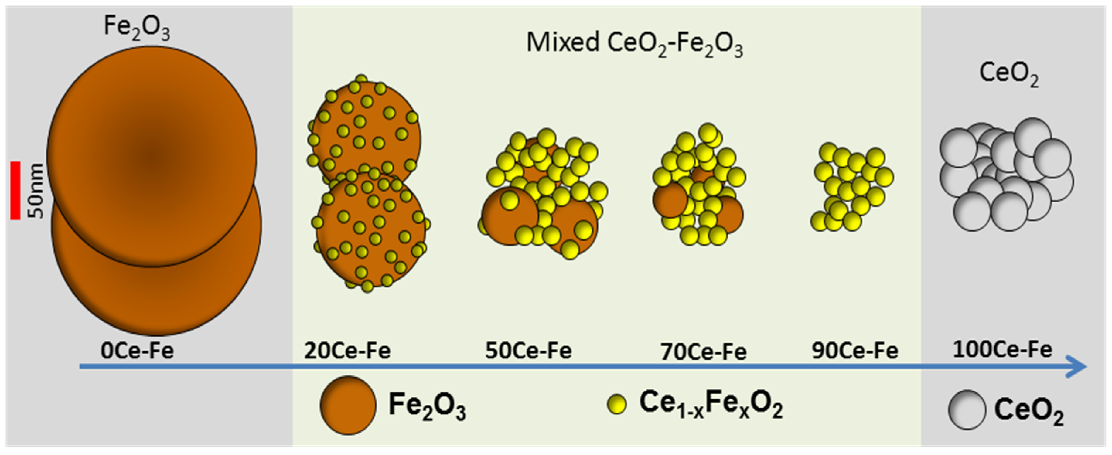
Figure 3.
Oxygen storage capacity of MgFexAl2−xO4 materials as a function of the Fe2O3 content. Note that when Fe2O3 loading is less than 30 wt %, it is completely incorporated into the spinel structure without separate Fe2O3 phases. ![Materials 11 00831 i001]() : iron incorporated in spinel structure;
: iron incorporated in spinel structure; ![Materials 11 00831 i002]() : separate Fe2O3 phase. Obtained from [81].
: separate Fe2O3 phase. Obtained from [81].
 : iron incorporated in spinel structure;
  : separate Fe2O3 phase. Obtained from [81].
Figure 3.
Oxygen storage capacity of MgFexAl2−xO4 materials as a function of the Fe2O3 content. Note that when Fe2O3 loading is less than 30 wt %, it is completely incorporated into the spinel structure without separate Fe2O3 phases. ![Materials 11 00831 i001]() : iron incorporated in spinel structure;
: iron incorporated in spinel structure; ![Materials 11 00831 i002]() : separate Fe2O3 phase. Obtained from [81].
: separate Fe2O3 phase. Obtained from [81].
: iron incorporated in spinel structure; : separate Fe2O3 phase. Obtained from [81].
Figure 4.
Crystallite size of Fe2O3 and MgFexAl2−xO4 phases in the samples, as calculated based on XRD using the Scherrer equation. As-prepared: (□) MgFexAl2−xO4 and (Δ) Fe2O3; (■) MgFexAl2−xO4 and (▲) Fe3O4 after 5 isothermal redox cycles of H2/CO2 at 1023 K. Obtained from [81].
Figure 4.
Crystallite size of Fe2O3 and MgFexAl2−xO4 phases in the samples, as calculated based on XRD using the Scherrer equation. As-prepared: (□) MgFexAl2−xO4 and (Δ) Fe2O3; (■) MgFexAl2−xO4 and (▲) Fe3O4 after 5 isothermal redox cycles of H2/CO2 at 1023 K. Obtained from [81].

Figure 5.
CO yield in CO2 to CO conversion as a function of isothermal H2-CO2 redox cycles for MgFexAl2−xO4 and Fe2O3/MgFexAl2−xO4 with (●) 10 wt % Fe2O3 (MgFe0.14Al1.86O4) and (▲) 90 wt % Fe2O3. Each cycle (16 min) is composed of 4 min H2 (5% in Ar), 4 min He, 4 min CO2 (100%) and 4 min He at 1123 K. All the gas flows were 1.1 NmL/s. Obtained from [81].

Figure 6.
Schematic representation of the shrinking core model in a MgFexAl2−xO4 crystallite. Top right inset: Observed and calculated conversion profile of Fe3+ based on pre-edge fitting of QXANES spectra from MgFe0.14Al1.86O4. Obtained from [85].
Figure 6.
Schematic representation of the shrinking core model in a MgFexAl2−xO4 crystallite. Top right inset: Observed and calculated conversion profile of Fe3+ based on pre-edge fitting of QXANES spectra from MgFe0.14Al1.86O4. Obtained from [85].

Figure 7.
Conversion and product distribution of the RuxFe/TiO2 catalysts, during anisole hydrodeoxygenation (HDO), in a stainless-steel batch reactor. Reaction conditions: 10 wt % anisole (40 mL), catalyst (1.0 g), 200 °C and 10 bar H2 for 3 h. Obtained from [94].
Figure 7.
Conversion and product distribution of the RuxFe/TiO2 catalysts, during anisole hydrodeoxygenation (HDO), in a stainless-steel batch reactor. Reaction conditions: 10 wt % anisole (40 mL), catalyst (1.0 g), 200 °C and 10 bar H2 for 3 h. Obtained from [94].

Figure 8.
Phase diagram of the bimetallic Fe–Ni system. Obtained from [99].
Figure 8.
Phase diagram of the bimetallic Fe–Ni system. Obtained from [99].

Figure 9.
Full XRD scans of MgAl2O4, as-prepared, reduced and re-oxidized 8 wt %Ni-5 wt %Fe/MgAl2O4 (1 mL/s of 10%H2/He mixture or CO2 at a total pressure of 101.3 kPa and 1123 K). The NiFe2O4 phase cannot be distinguished due to overlapping with Fe2O3. Reproduced from [17].
Figure 9.
Full XRD scans of MgAl2O4, as-prepared, reduced and re-oxidized 8 wt %Ni-5 wt %Fe/MgAl2O4 (1 mL/s of 10%H2/He mixture or CO2 at a total pressure of 101.3 kPa and 1123 K). The NiFe2O4 phase cannot be distinguished due to overlapping with Fe2O3. Reproduced from [17].

Figure 10.
EDX element mapping of 8 wt %Ni-5 wt %Fe/MgAl2O4. (A) After H2-reduction (1 mL/s of 5%H2/Ar mixture at a total pressure of 101.3 kPa and 1123 K). (B) After CO2 oxidation (1 mL/s of CO2 at a total pressure of 101.3 kPa and 1123 K). Red and green colors correspond to Fe and Ni elements respectively. Obtained from [17].

Figure 11.
Schematic diagram of Fe–Ni nano-alloy formation and decomposition, depending on the applied environment. Obtained from [17].
Figure 11.
Schematic diagram of Fe–Ni nano-alloy formation and decomposition, depending on the applied environment. Obtained from [17].
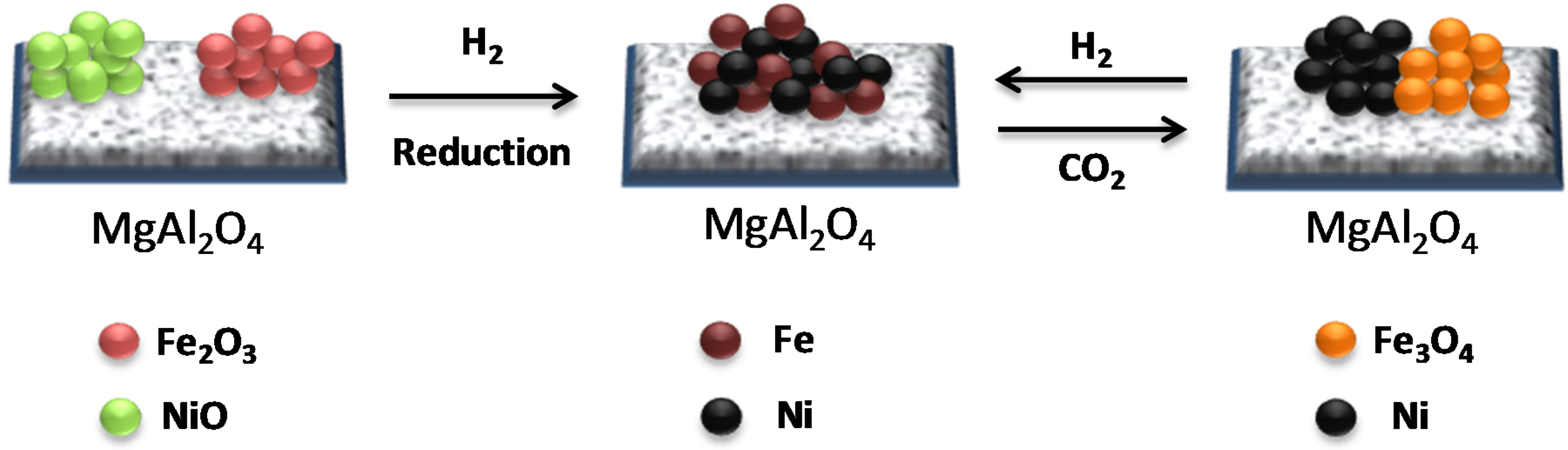
Figure 12.
(A) Methane conversion over Fe–Ni catalysts with Ni/(Ni + Fe) ratio of 1.0, 0.7 and 0.3 as a function of TOS at 873 K. (B) Long term test of a Fe–Ni catalyst with Ni/(Ni + Fe) ratio of 0.7 during methane decomposition at 923 K. Reproduced from [110].
Figure 12.
(A) Methane conversion over Fe–Ni catalysts with Ni/(Ni + Fe) ratio of 1.0, 0.7 and 0.3 as a function of TOS at 873 K. (B) Long term test of a Fe–Ni catalyst with Ni/(Ni + Fe) ratio of 0.7 during methane decomposition at 923 K. Reproduced from [110].
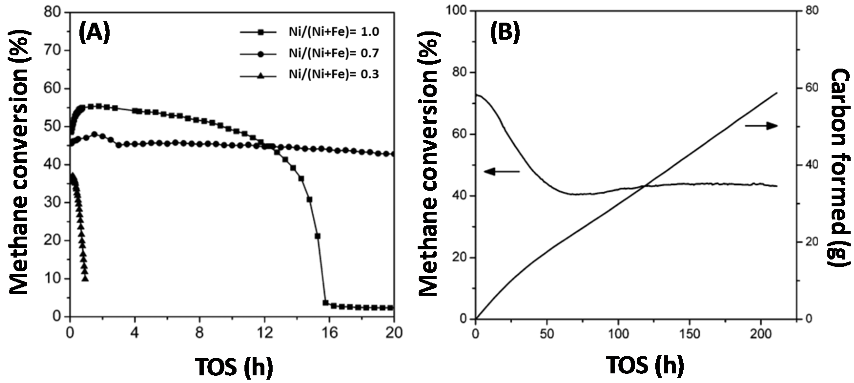
Figure 13.
SEM image of carbon nanotubes produced over a Fe–Ni catalyst with Ni/(Ni + Fe) of 0.7 after 210 h TOS under methane decomposition at 923 K. Obtained from [110].
Figure 13.
SEM image of carbon nanotubes produced over a Fe–Ni catalyst with Ni/(Ni + Fe) of 0.7 after 210 h TOS under methane decomposition at 923 K. Obtained from [110].

Figure 14.
(A) Rate of methane consumption (mol·min−1·kg−1cat) as a function of the amount of surface Ni (mmol), during methane dry reforming. ■: Pure Ni; ▲: Ni/(Ni + Fe) = 0.80; ●: Ni/(Ni + Fe) = 0.75; □: Ni/(Ni + Fe) = 0.5; ∆: Ni/(Ni + Fe) = 0.25 and ○: Pure Fe, all supported on MgxAlyOz and (B) rate of methane consumption (mol·min−1·kg−1cat) as a function of time-on-stream (TOS) during DRM at 923 K. Reproduced from [101].
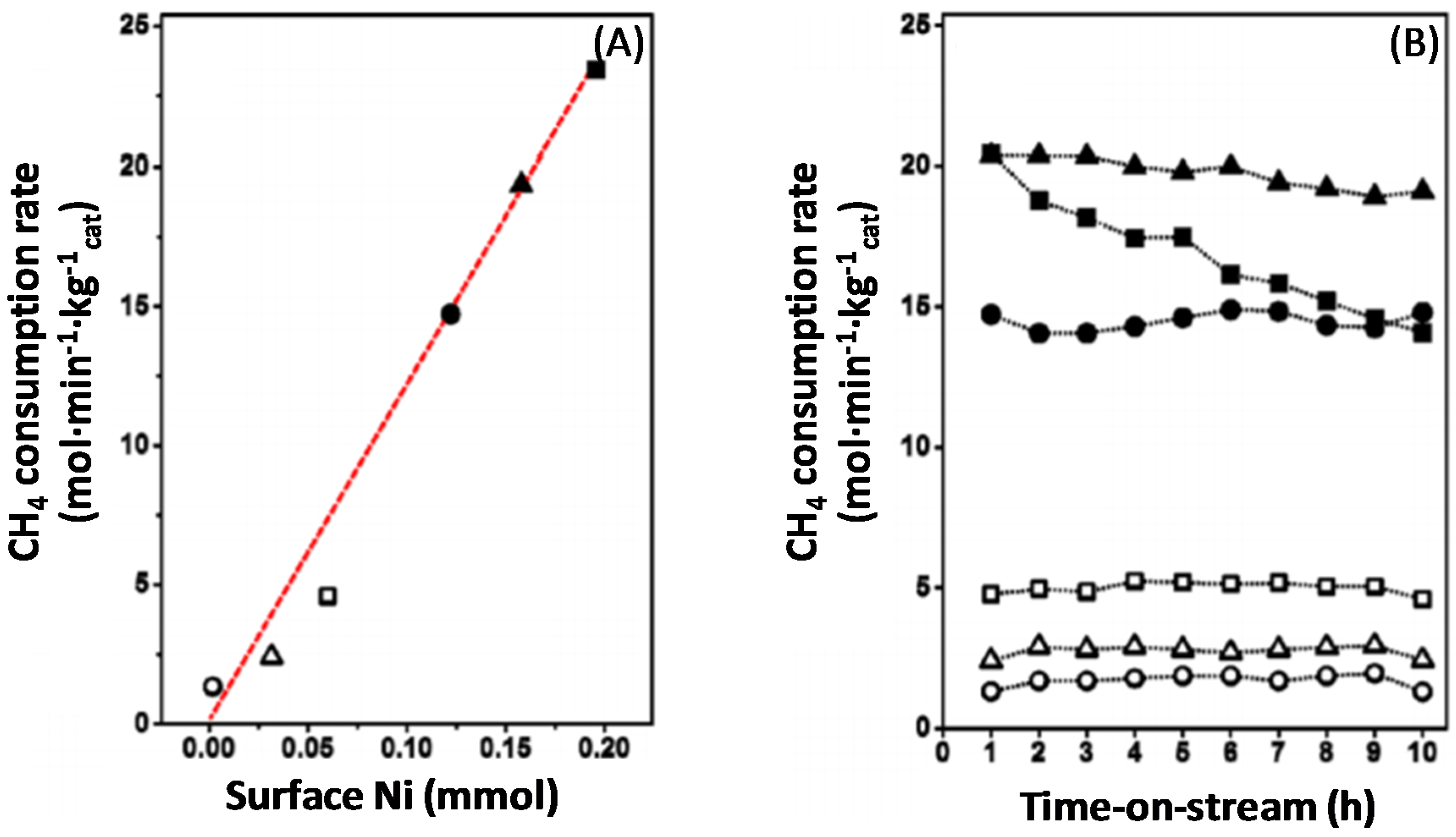
Figure 15.
Deposited carbon as a function of Ni/(Ni + Fe) ratio along with the SEM micrographs of “spent” catalysts supported on MgAl2O4. Temperature 1023 K, CH4:CO2 = 1:1, reaction time 4 h. Reproduced from [17].
Figure 15.
Deposited carbon as a function of Ni/(Ni + Fe) ratio along with the SEM micrographs of “spent” catalysts supported on MgAl2O4. Temperature 1023 K, CH4:CO2 = 1:1, reaction time 4 h. Reproduced from [17].
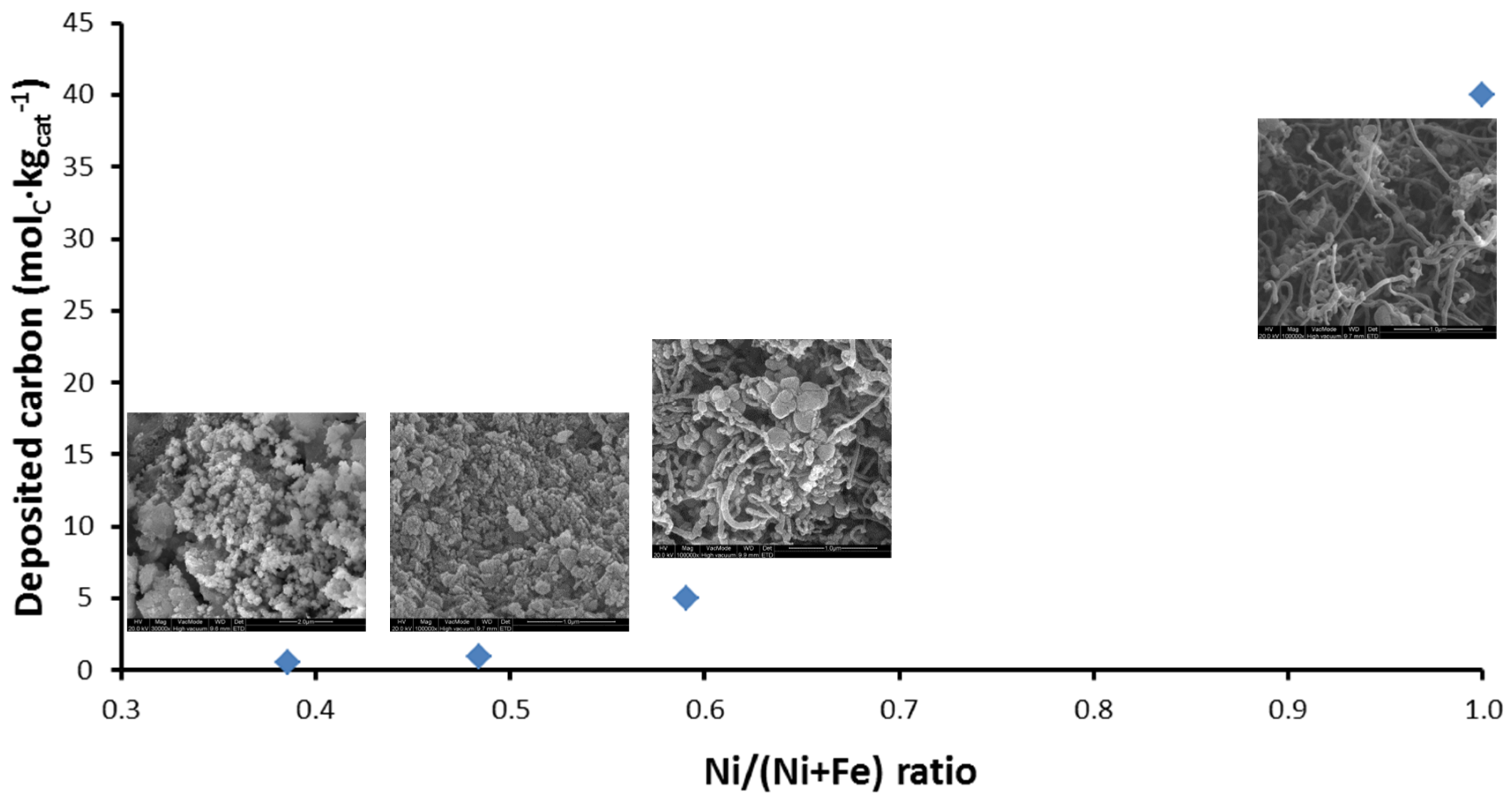
Figure 16.
CH4 consumption rate (molCH4·s−1·kg−1metals) and the produced CO/H2 ratio over a bimetallic Fe–Ni catalyst with Ni/(Ni + Fe) = 0.65 during DRM at 1023 K (total pressure of 101.3 kPa and CH4:CO2 = 1:1). Wmetals/F0CH4 = 0.025 molCH4·s−1·kg−1metals, XCH4: from 62% to 24%. Reproduced from [116].

Figure 17.
Phase diagram showing the equilibrium lines between Fe3O4, FeO and Fe as a function of temperature and reduction capacity in presence of: ![Materials 11 00831 i003]() H2/H2O;
H2/H2O; ![Materials 11 00831 i004]() H2/CO/H2O/CO2 (equimolar amount of C and H2 corresponding with a feed of CH4 + CO2);
H2/CO/H2O/CO2 (equimolar amount of C and H2 corresponding with a feed of CH4 + CO2); ![Materials 11 00831 i005]() CO/CO2. Obtained from [49].
CO/CO2. Obtained from [49].
 H2/H2O;
  H2/CO/H2O/CO2 (equimolar amount of C and H2 corresponding with a feed of CH4 + CO2);
  CO/CO2. Obtained from [49].
Figure 17.
Phase diagram showing the equilibrium lines between Fe3O4, FeO and Fe as a function of temperature and reduction capacity in presence of: ![Materials 11 00831 i003]() H2/H2O;
H2/H2O; ![Materials 11 00831 i004]() H2/CO/H2O/CO2 (equimolar amount of C and H2 corresponding with a feed of CH4 + CO2);
H2/CO/H2O/CO2 (equimolar amount of C and H2 corresponding with a feed of CH4 + CO2); ![Materials 11 00831 i005]() CO/CO2. Obtained from [49].
CO/CO2. Obtained from [49].
H2/H2O; H2/CO/H2O/CO2 (equimolar amount of C and H2 corresponding with a feed of CH4 + CO2); CO/CO2. Obtained from [49].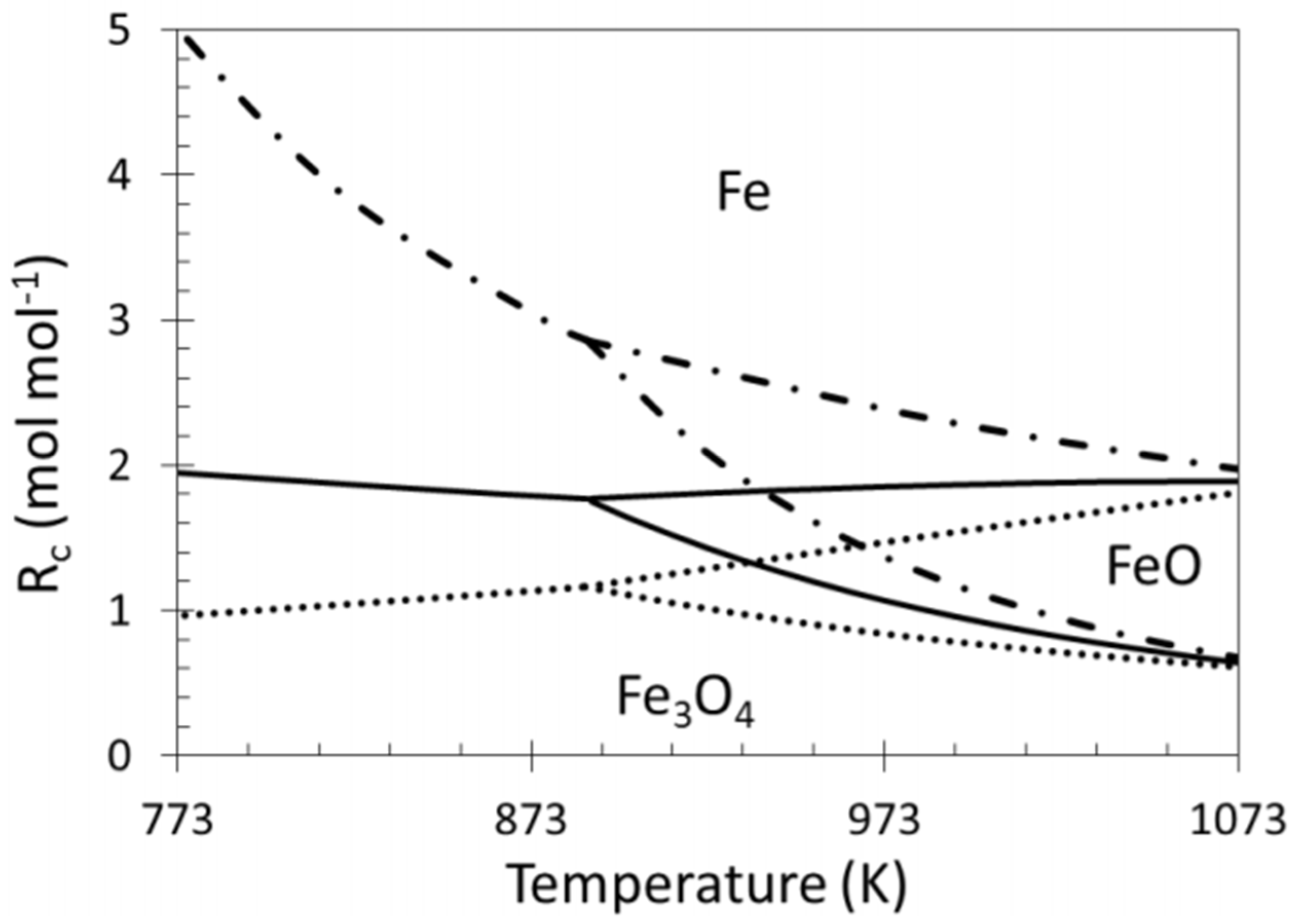
Figure 18.
Deactivation due to Fe segregation from the Fe–Ni surface alloy during DRM at high temperature (1023 K). Obtained from [116].
Figure 18.
Deactivation due to Fe segregation from the Fe–Ni surface alloy during DRM at high temperature (1023 K). Obtained from [116].
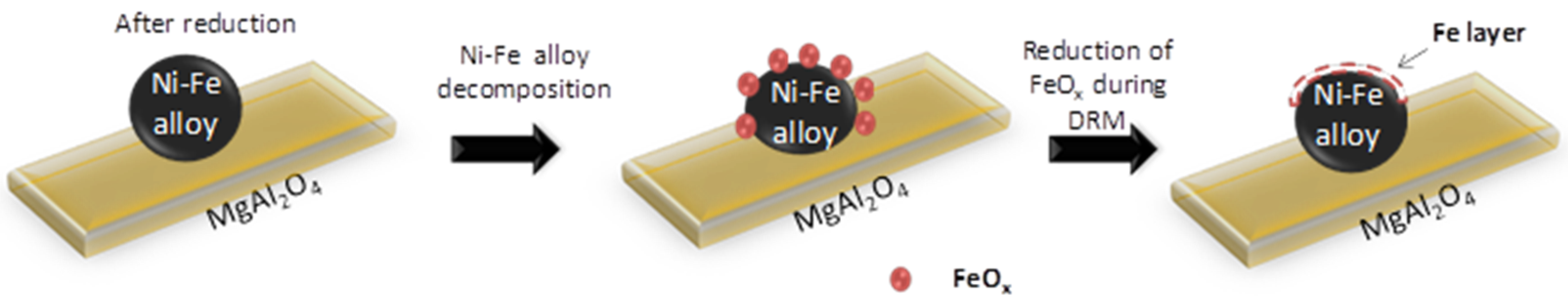
Figure 19.
Raman spectrum of the spent Fe–Ni catalyst, with Ni/(Ni + Fe) ratio of 0.6 (DRM for 1 h, 1023 K, CH4:CO2 = 1.1, total pressure of 101.3 kPa). Blue line: pure graphite as a reference, black line: spent Fe–Ni catalyst, grey line: spent Fe–Ni catalyst after CO2-TPO up to 950 K, purple line: Spent Fe–Ni catalyst after CO2-TPO up to 1123 K. Obtained from [118].

Figure 20.
(A) HRTEM image of a spent Fe–Ni catalyst with Ni/(Ni + Fe) ratio of 0.6 (after DRM at 1023 K, CH4:CO2:He = 1.1:1:1, total pressure of 101.3 kPa, reaction time 1 h). EDX element mapping of (B) carbon, (C) Ni and (D) Fe. Obtained from [118].
Figure 20.
(A) HRTEM image of a spent Fe–Ni catalyst with Ni/(Ni + Fe) ratio of 0.6 (after DRM at 1023 K, CH4:CO2:He = 1.1:1:1, total pressure of 101.3 kPa, reaction time 1 h). EDX element mapping of (B) carbon, (C) Ni and (D) Fe. Obtained from [118].

Figure 21.
EDX element mapping of Fe–Ni. (A) After DRM (1023 K, CH4/CO2/He = 1.1/1/1, total pressure of 101.3 kPa, reaction time 1 h). (B) After CO2 oxidation (1 mL/s of CO2 at a total pressure of 101.3 kPa and 1123 K). Red, green and blue colors correspond to carbon, Fe and Ni elements respectively. Obtained from [118].

Figure 22.
Schematic representation of carbon species removal by CO2 over Fe–Ni catalyst. Cs: deposited carbon. Os: surface oxygen, OL: lattice oxygen. Cm: carbon deposited on metals, Cs: Carbon deposited far from metals, Os: surface oxygen, OL: lattice oxygen. The carbon illustration is not corresponding to the real carbon structure. Obtained from [118].

Figure 23.
2D in situ XRD pattern during H2-TPR for Fe–Ni–Pd. Heating rate: 30 K/min, maximum temperature 1123 K, flow rate: 1 NmL/s, 10%H2/He. Obtained from [116].
Figure 23.
2D in situ XRD pattern during H2-TPR for Fe–Ni–Pd. Heating rate: 30 K/min, maximum temperature 1123 K, flow rate: 1 NmL/s, 10%H2/He. Obtained from [116].
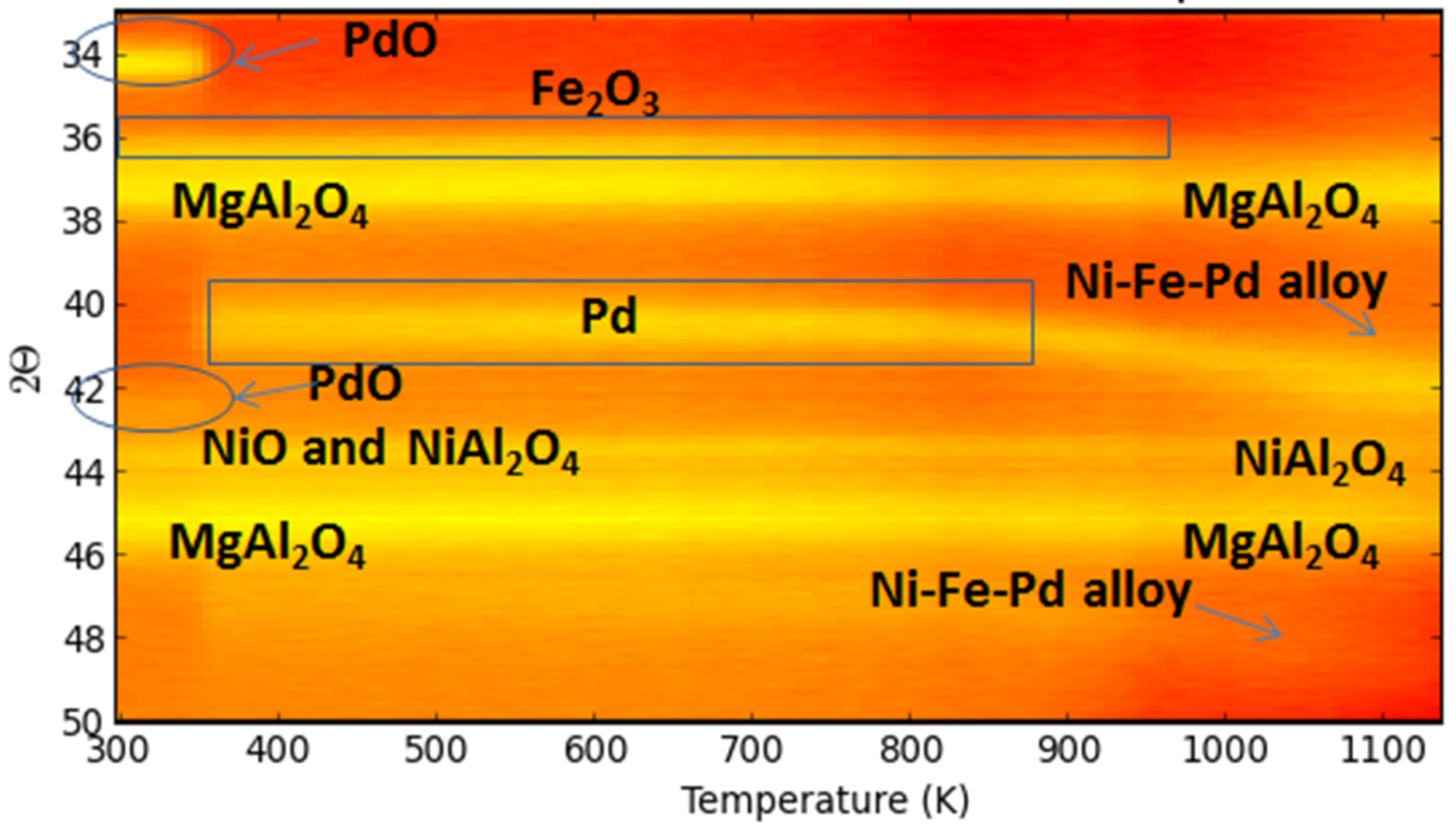
Figure 24.
EDX element mapping of a Fe–Ni–Pd catalyst supported on MgAl2O4. (A) as-prepared (B) reduced (1 NmL/s of 5%H2/He mixture at a total pressure of 101.3 kPa and 1123 K). Red, green and blue colors correspond to Fe, Ni and Pd elements, respectively. Obtained from [116].
Figure 24.
EDX element mapping of a Fe–Ni–Pd catalyst supported on MgAl2O4. (A) as-prepared (B) reduced (1 NmL/s of 5%H2/He mixture at a total pressure of 101.3 kPa and 1123 K). Red, green and blue colors correspond to Fe, Ni and Pd elements, respectively. Obtained from [116].


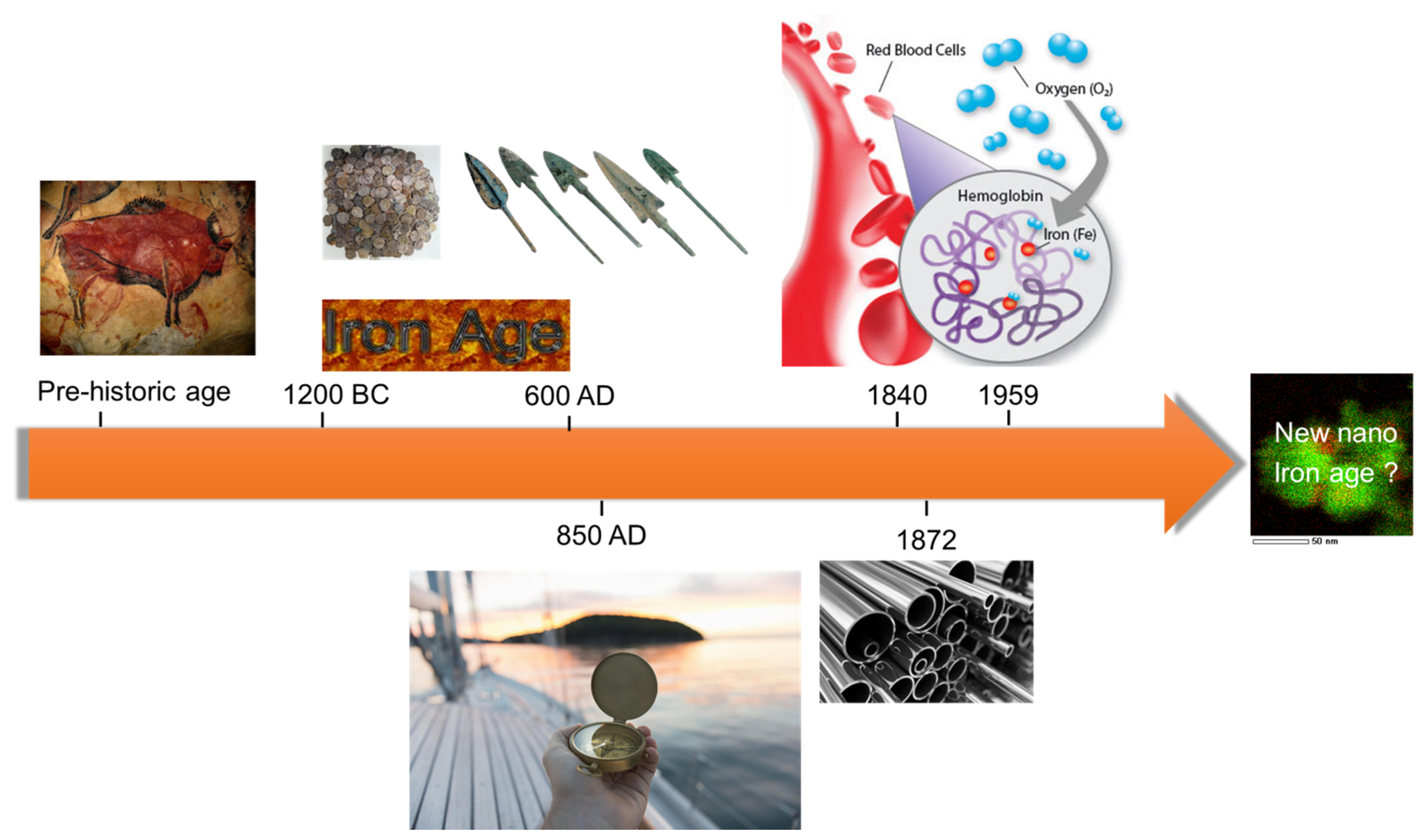
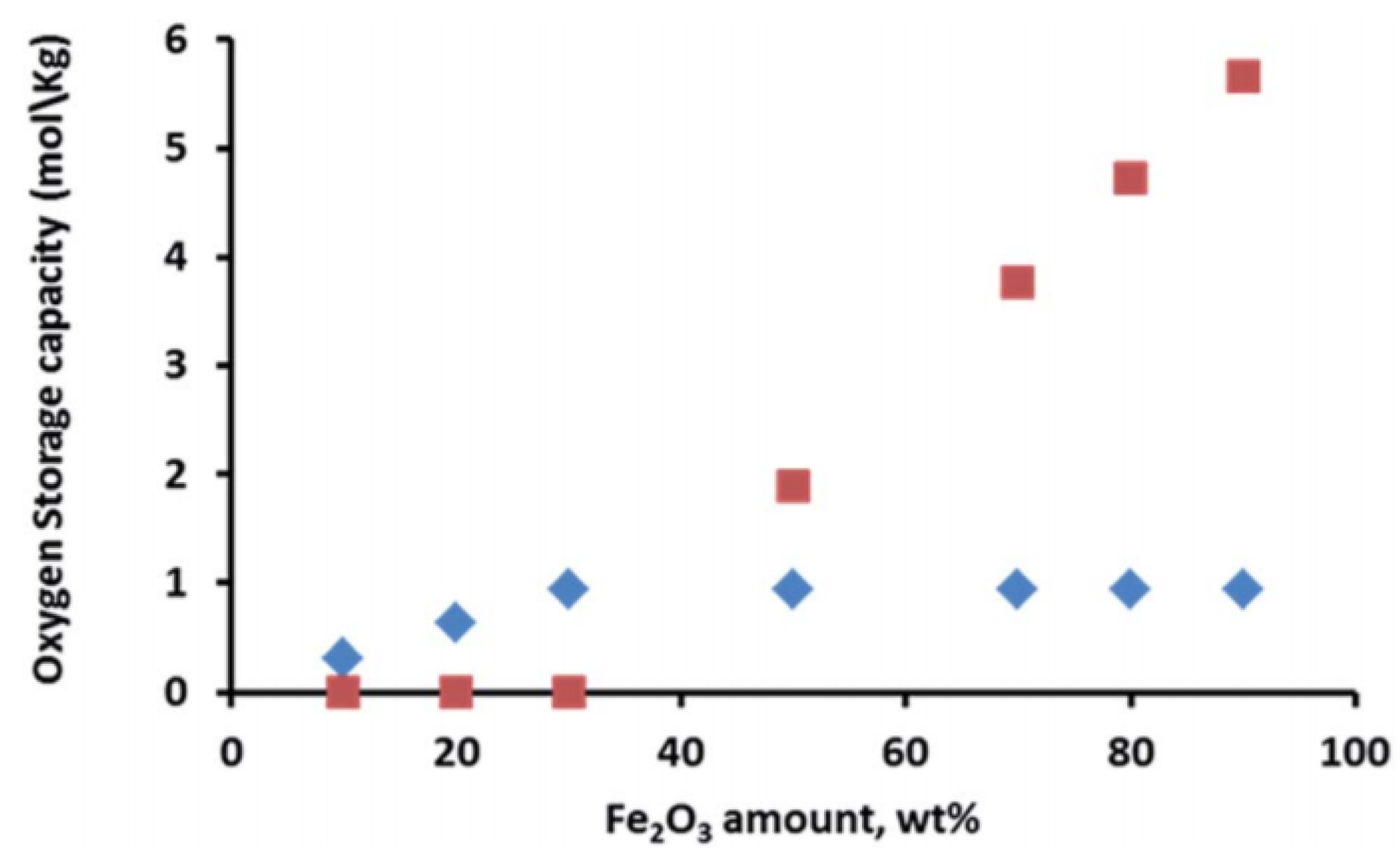
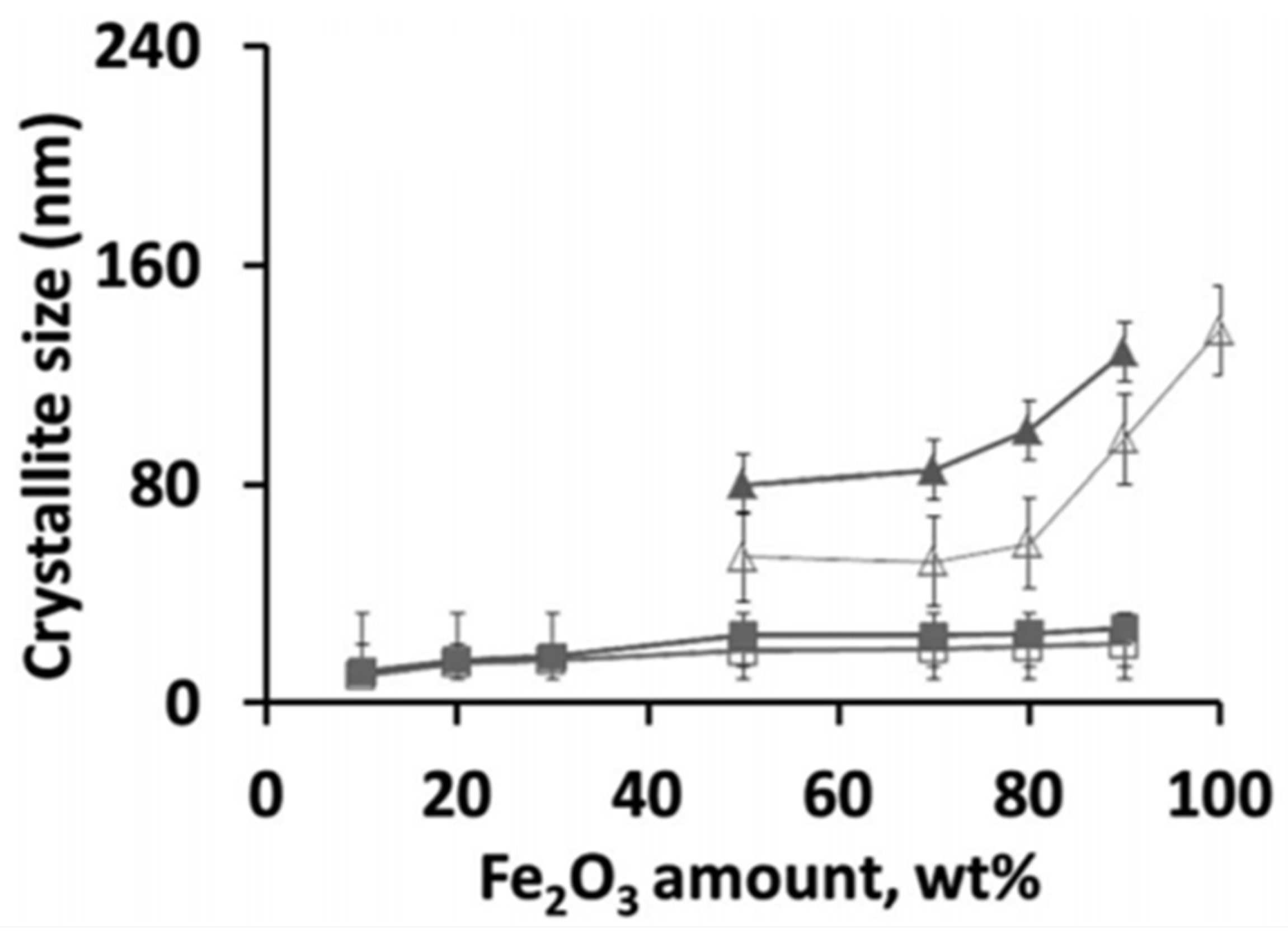
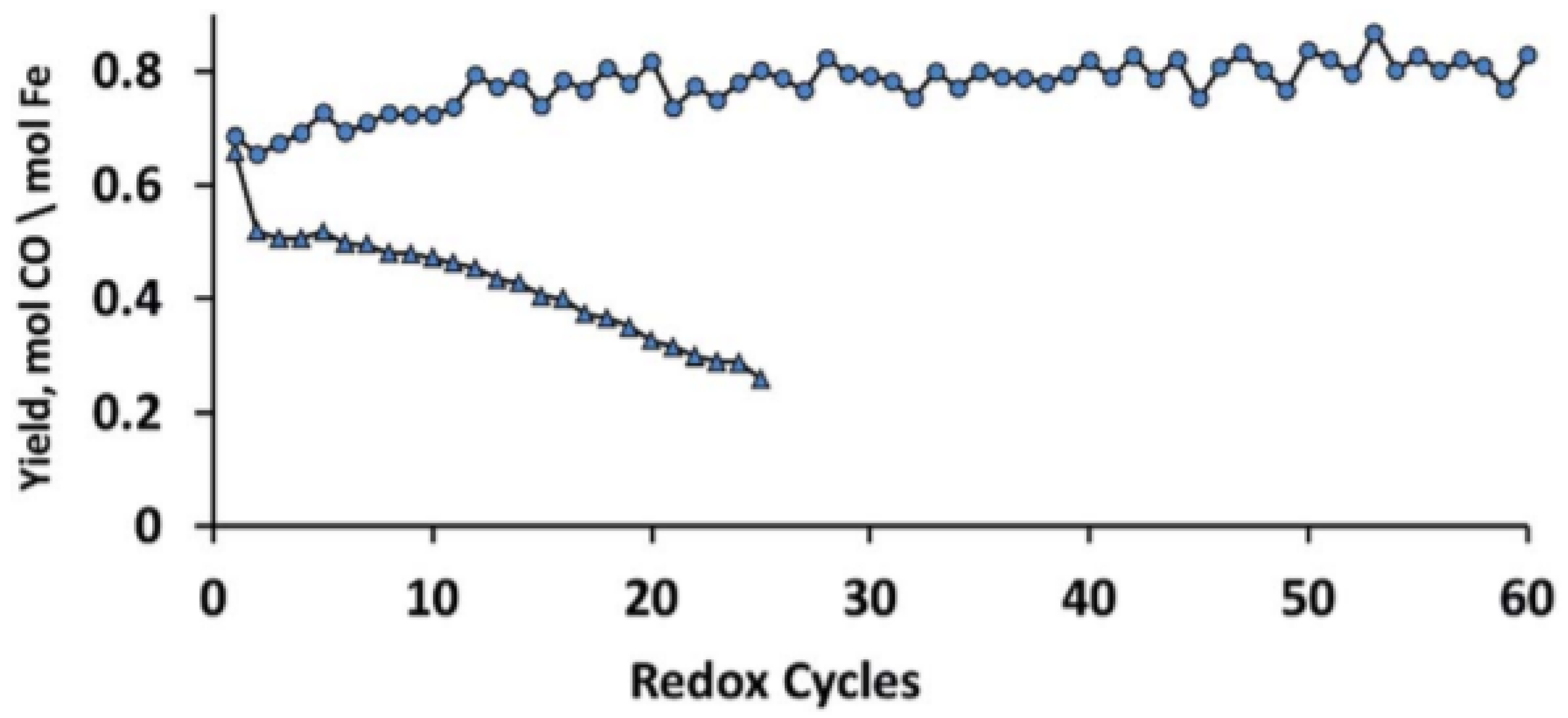
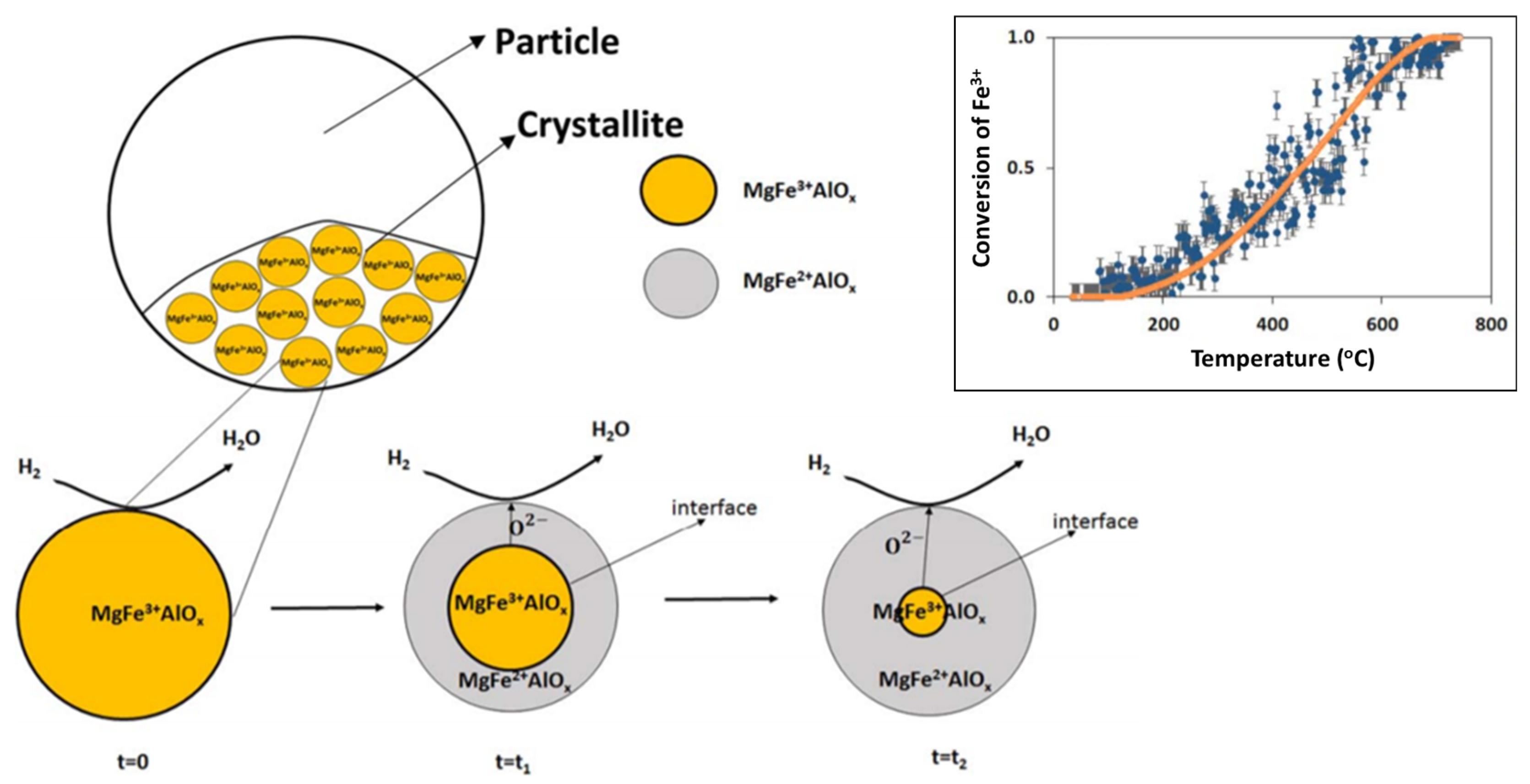
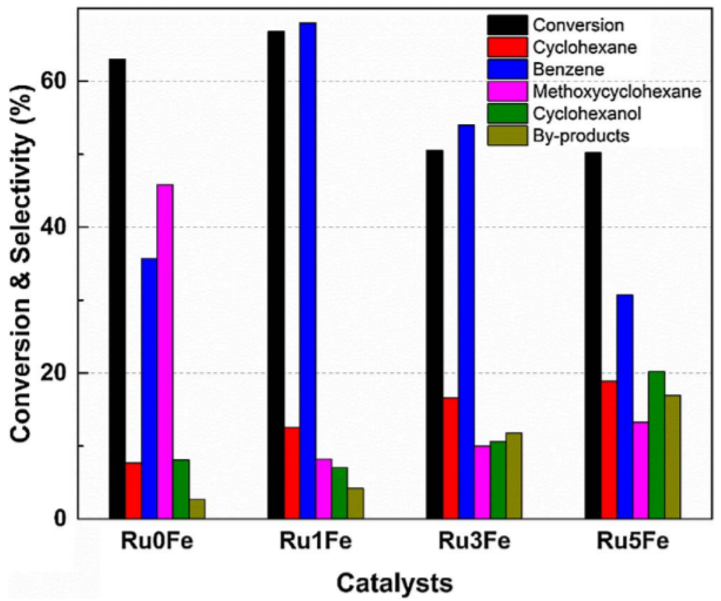
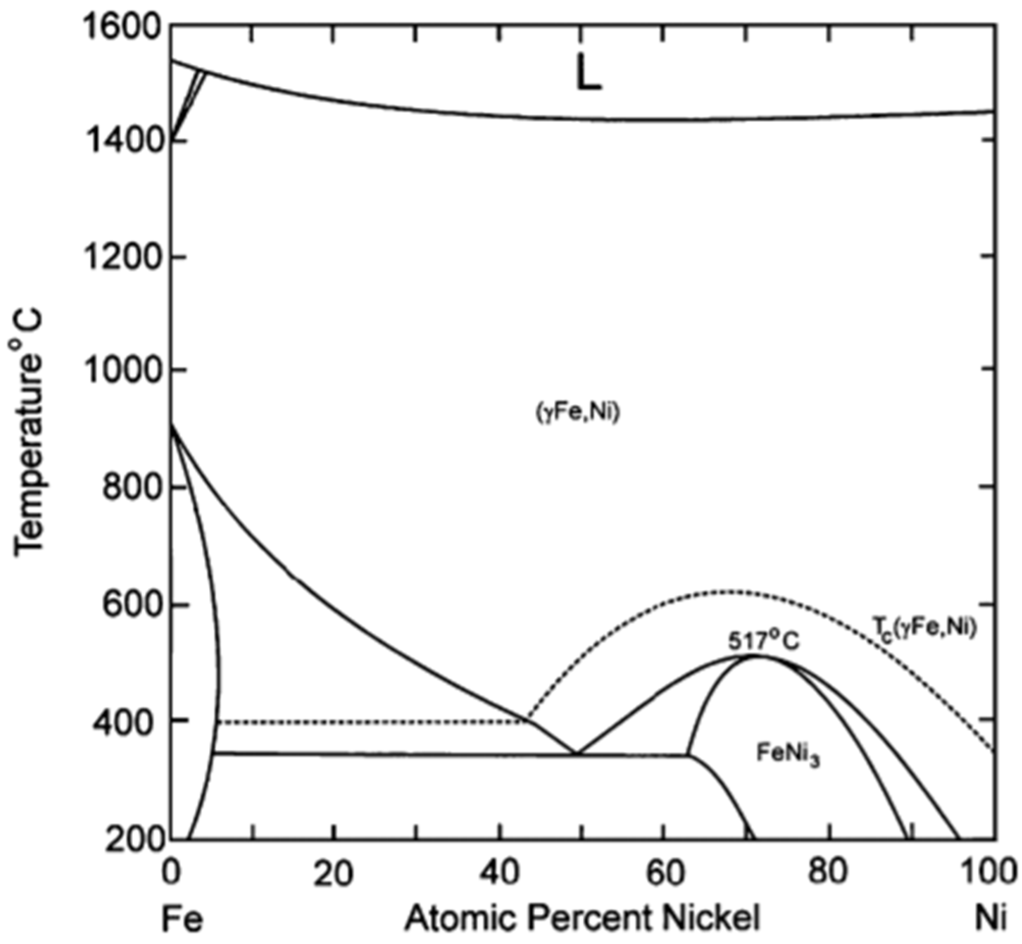
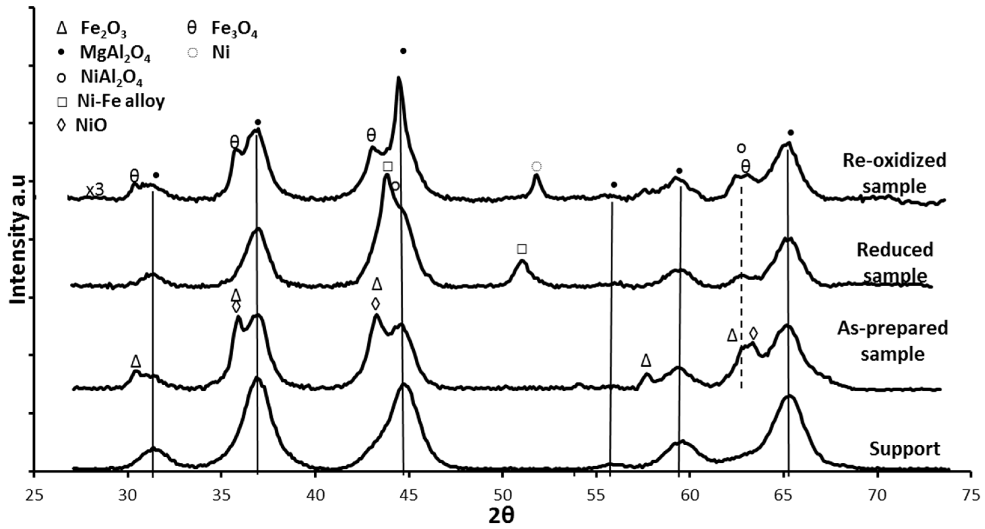
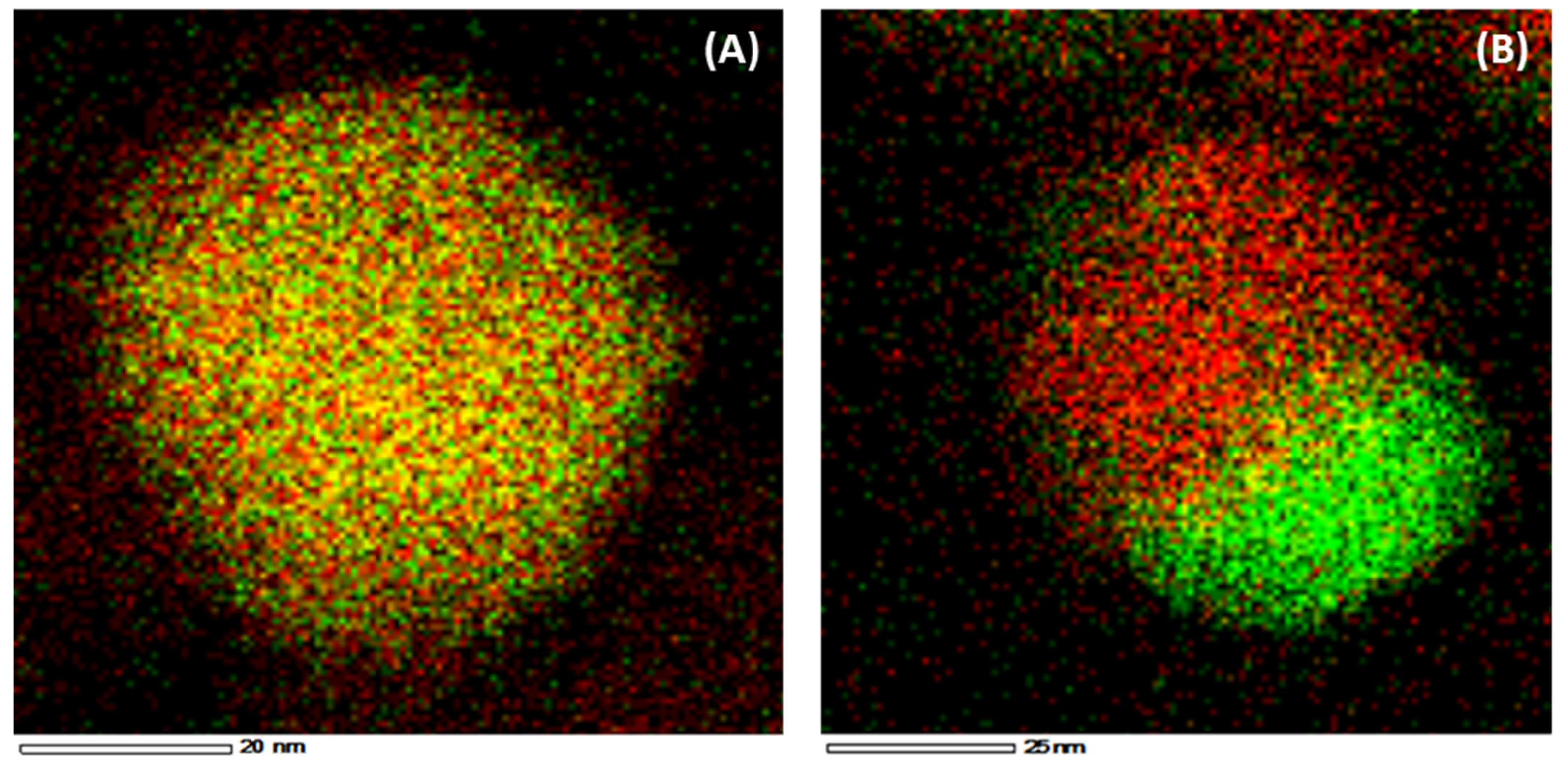
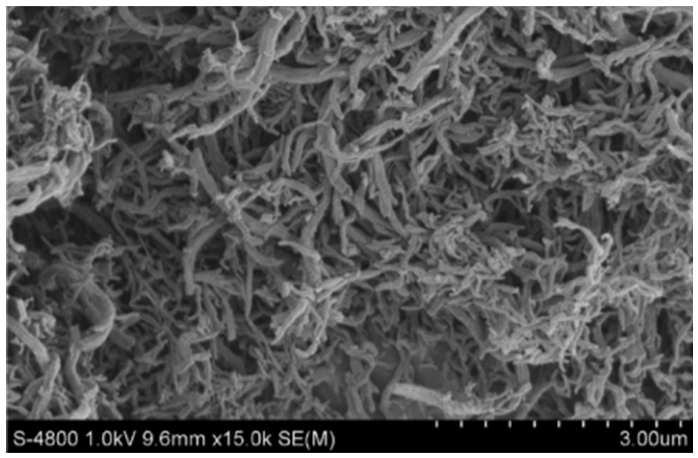
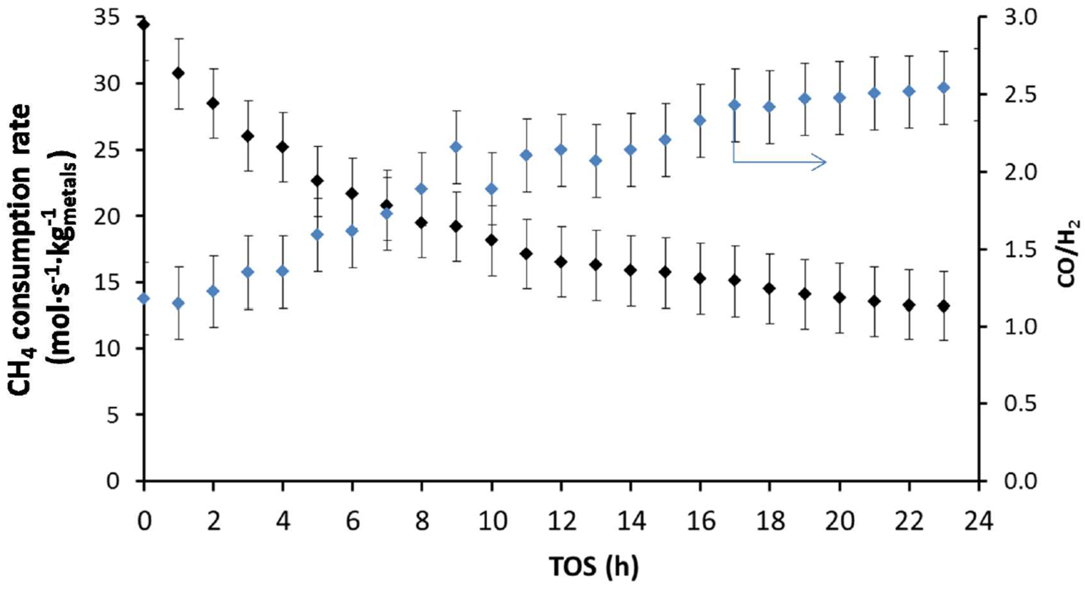
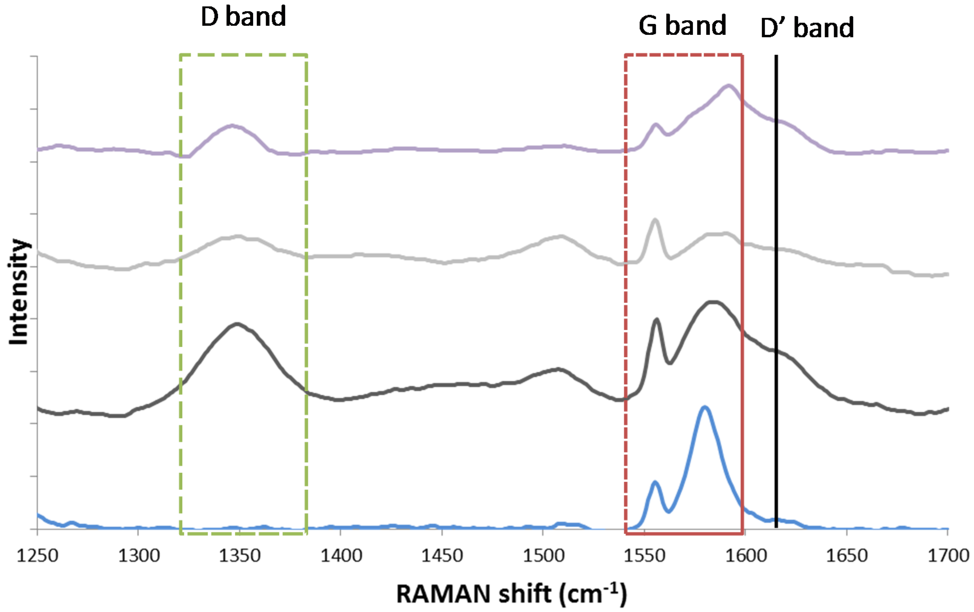
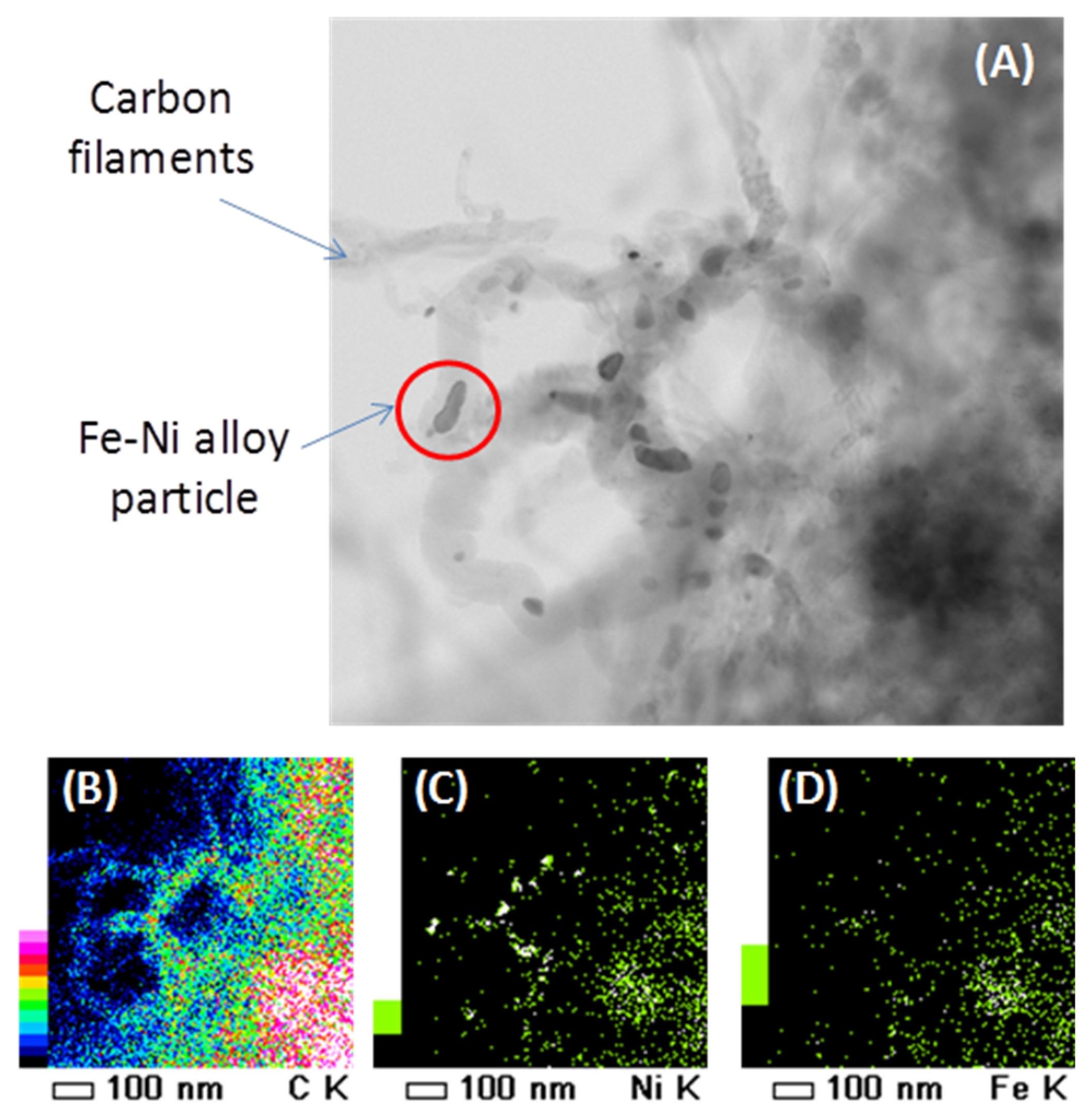
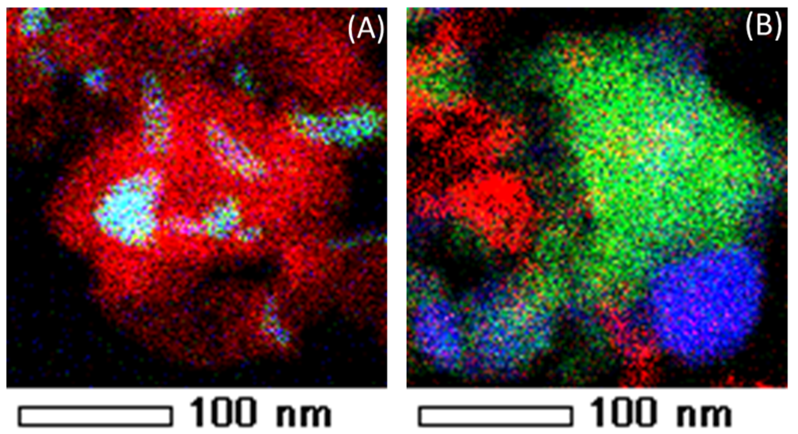
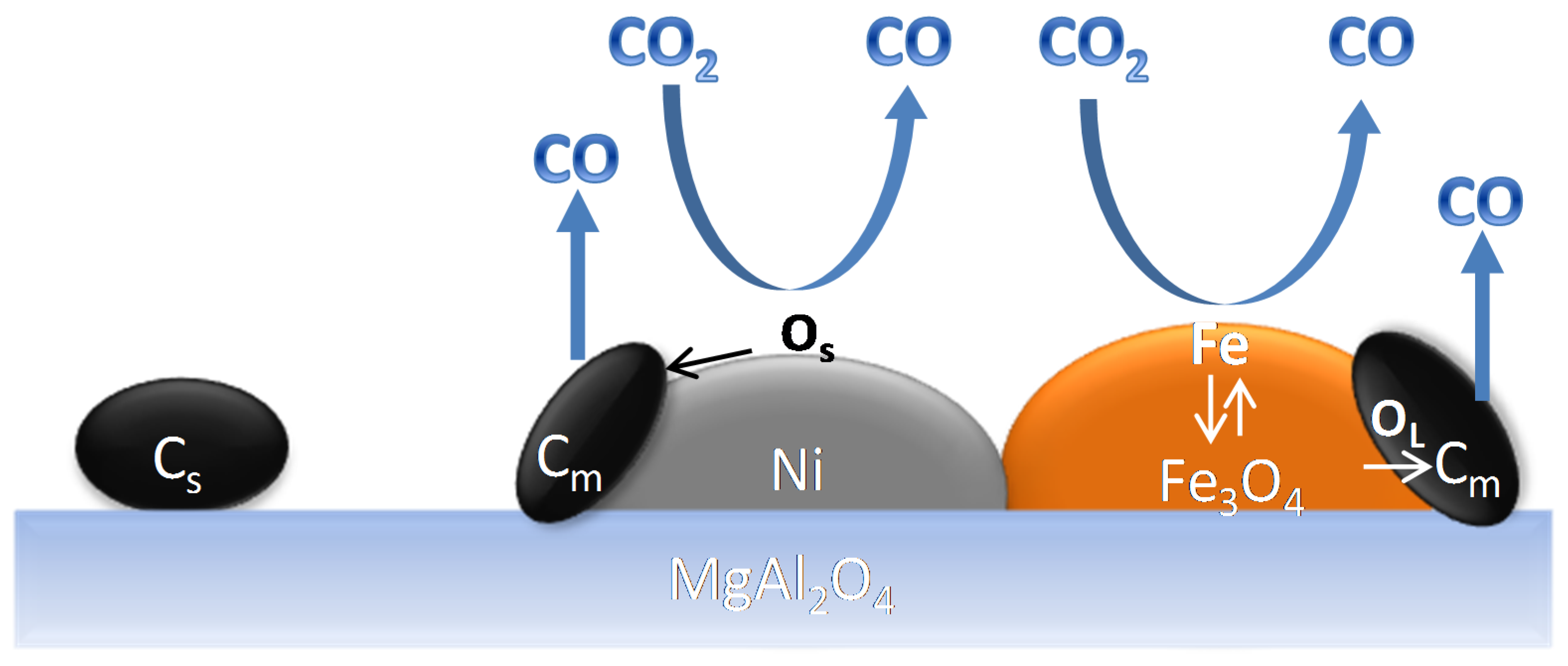
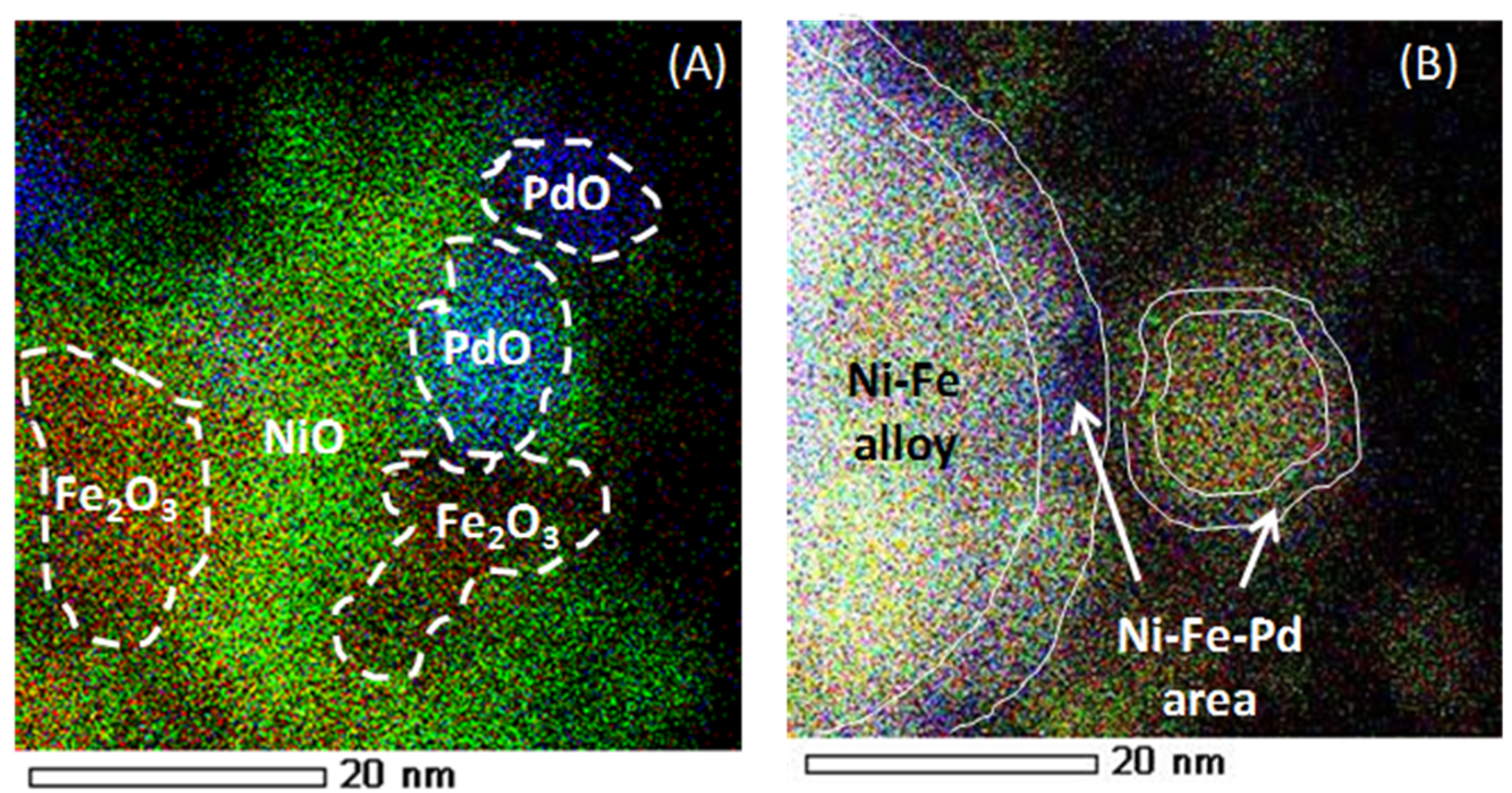
Table 1.
Segregation energies without (ΔEseg, kJ/mol) and with adsorbates () for the exchange of Fe in the subsurface layer of a (111) surface of Ni3Fe or Ni2FePd, with Ni or Pd from the surface layer, for various coverages, representative for methane dry reforming (DRM). All coverages refer to the species adsorbed on the fcc sites of a periodically repeated unit cell with 4 surface atoms. Obtained from [116].
| ΔEseg (kJ/mol) | Ni3Fe | Ni2PdFe | |
|---|---|---|---|
| Adsorbate Overlayer | Fe ↔ Ni | Fe ↔ Ni | Fe ↔ Pd |
| 0% (vacuum) | +55 | +53 | +104 |
| 100% H | +49 | +52 | +43 |
| 100% CO | +29 | +42 | +3 |
| 100% O | −94 | −76 | −218 |
| 50% CO, 50% O | −25 | −8 | −92 |
| 50% CO, 25% O, 25% H | +1 | +11 | +38 |
| 25% of CH, CO, O, H | +2 | +9 | +143 |
© 2018 by the authors. Licensee MDPI, Basel, Switzerland. This article is an open access article distributed under the terms and conditions of the Creative Commons Attribution (CC BY) license (http://creativecommons.org/licenses/by/4.0/).
Share and Cite
MDPI and ACS Style
Theofanidis, S.A.; Galvita, V.V.; Konstantopoulos, C.; Poelman, H.; Marin, G.B. Fe-Based Nano-Materials in Catalysis. Materials 2018, 11, 831. https://doi.org/10.3390/ma11050831
AMA Style
Theofanidis SA, Galvita VV, Konstantopoulos C, Poelman H, Marin GB. Fe-Based Nano-Materials in Catalysis. Materials. 2018; 11(5):831. https://doi.org/10.3390/ma11050831
Chicago/Turabian StyleTheofanidis, Stavros Alexandros, Vladimir V. Galvita, Christos Konstantopoulos, Hilde Poelman, and Guy B. Marin. 2018. "Fe-Based Nano-Materials in Catalysis" Materials 11, no. 5: 831. https://doi.org/10.3390/ma11050831
Note that from the first issue of 2016, this journal uses article numbers instead of page numbers. See further details here.