3.1. Microstructures of Plasma Spray Welded Coating
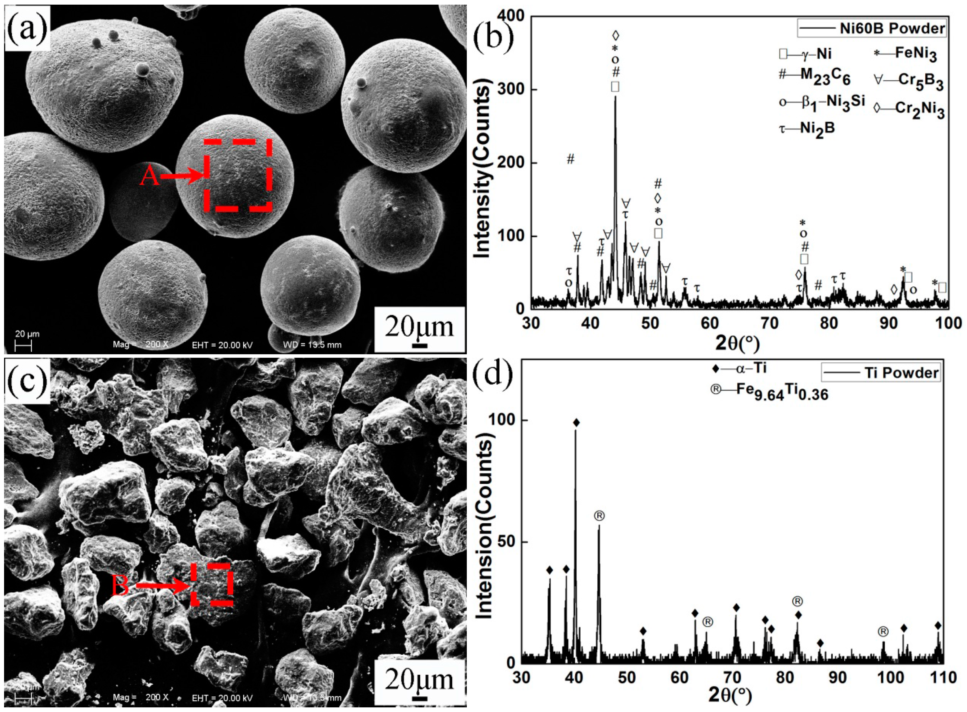
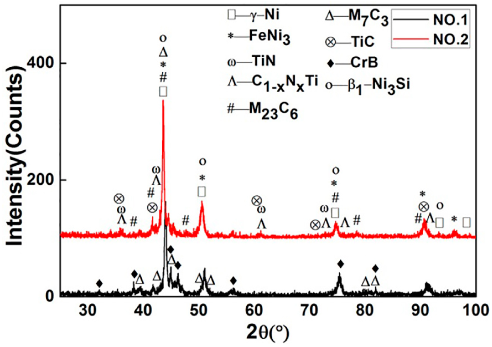
Figure 2 shows XRD patterns of specimens No.1 and No.2, respectively. The phases of γ-Ni, FeNi
3, β
1-Ni
3Si, CrB, Cr
7C
3, (Cr,Fe)
7C
3, Cr
23C
6, and (Cr,Fe)
23C
6 were identified in the coatings of both No.1 and No.2. From the XRD comparison of No.1 coating and Ni60B powder, new phase CrB was formed but Cr
5B
3 and Cr
2Ni
3 disappeared after plasma spray welding. In the coating of No.2, a large amount of TiN, C
1-xN
xTi, and a small amount of TiC were found, which derived from gas-solid in-situ reaction. Both TiN and TiC have cubic atomic crystal structure and similar lattice constants. Further, C and N atoms have similar radius. Therefore, element C can be combined with TiN infinitely to form C
1-xN
xTi. The experiment proved that these hard phases greatly increased the wear resistance of the coating. Further study revealed that FeNi
3 and β
1-Ni
3Si decreased in the No.2 coating compared with 85% Ni60B + 15% Ti powder. As a kind of hard and brittle phase, the decrease of β
1-Ni
3Si can also improve the wear resistance of the coating.
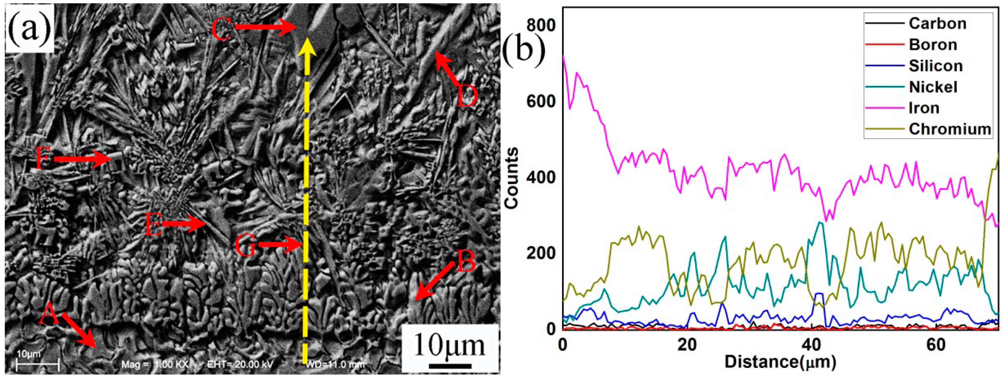
Figure 3 and
Table 4 present the SEM microstructure and EDS analysis of No.1 interface between coating and steel substrate, respectively. It could be observed that the coating and substrate formed metallurgical bonding. The width of the fusion zone (
Figure 3a) was about 8–10 μm. According to the EDS line scanning analysis, the substrate was rich in element Fe, which gradually decreased from interface to the top coating. This also indicated that element Fe in substrate diffused into the coating during the process of plasma spray welding. In contrast, the EDS analysis showed that the proportion of elements Ni, Cr, B, and Si in the coating were higher than that in the substrate. From
Figure 3a, the coating consisted of columnar grains (B) and irregular carbon precipitates (C, D, E, and F) which were embedded in the matrix. Based on the XRD and EDS results, it could be identified that the matrix of the coating was mainly Ni
3Si, γ-Ni, and FeNi
3. The long flakiness shaped carbon precipitates D and irregularly shaped carbon precipitates with holes C were (Cr,Fe)
7C
3. However, carbon precipitates D had higher Fe and lower Cr content than that of carbon precipitates C. Both the needle shaped carbon precipitates E and irregular flakiness shaped carbon precipitates F were (Cr,Fe)
23C
6, but carbon precipitates E had higher Fe and lower Cr content than that of microstructure F. It could be concluded that the lower Fe content in (Cr,Fe)
7C
3 or (Cr,Fe)
23C
6 contributed to decreasing the size of the microstructures, which would increase the wear resistance of the plasma spray welded coatings.
Figure 4 presents the SEM microstructure and EDS analysis of the middle part of plasma spray welded specimen No.1. Based on the XRD and EDS results, different shape microstructures were identified as in
Table 5. Combined with phase diagram study, it could be concluded that during the process of plasma spray welding, (Cr,Fe)
7C
3 and (Cr,Fe)
23C
6 first nucleated about 1766 °C and 1576 °C, respectively. The phase γ-(Ni,Fe) precipitated at about 1440 °C and then partly transformed to eutectic microstructures β
3-Ni
3Si + γ-Ni at about 1143 °C, which would turn into β
1-Ni
3Si + γ-Ni with temperature further lowering. When the welding pool reached about 517 °C, phase γ-(Ni,Fe) at high temperature transformed into phase FeNi
3, which could only exist at low temperature.
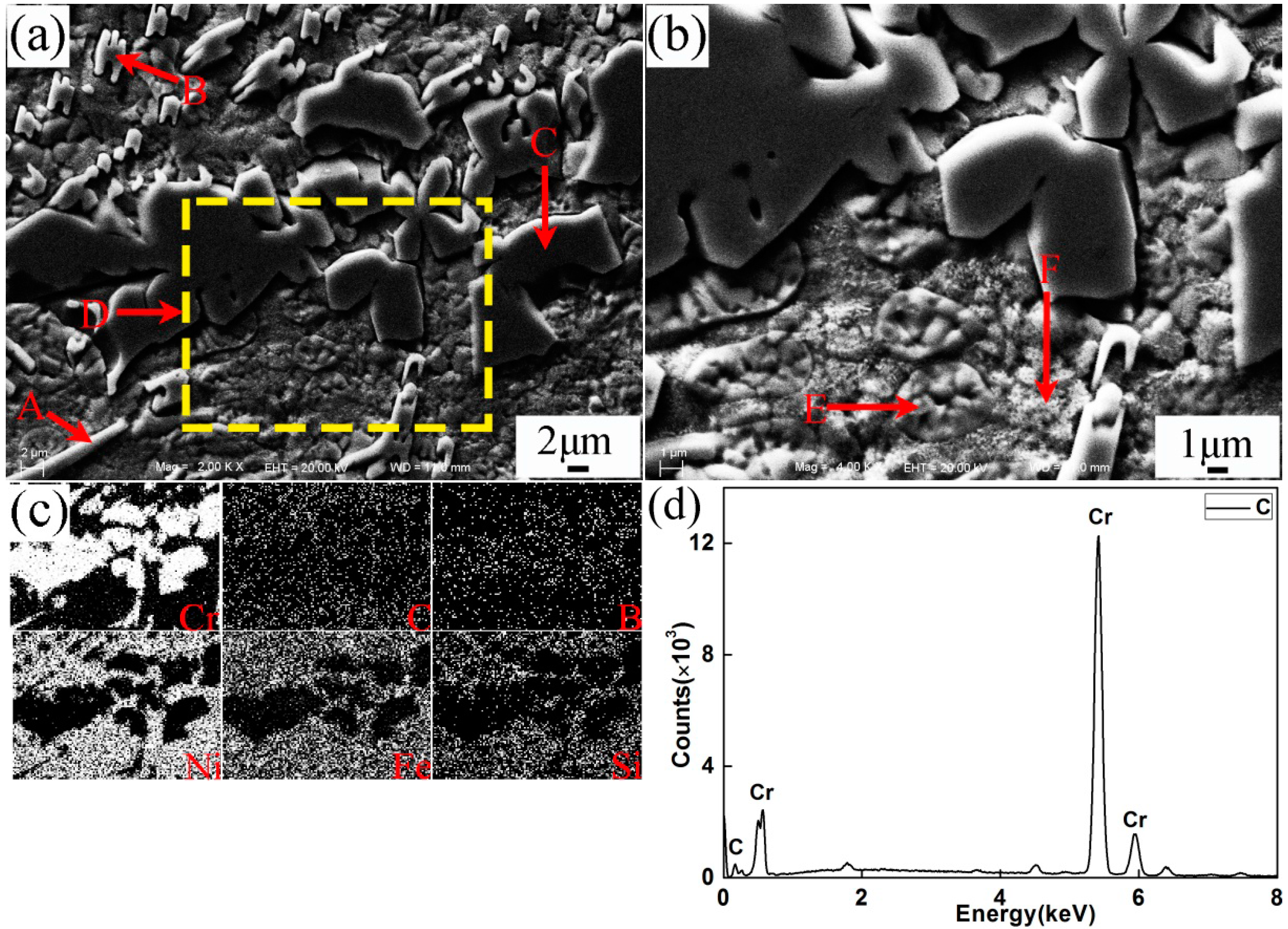
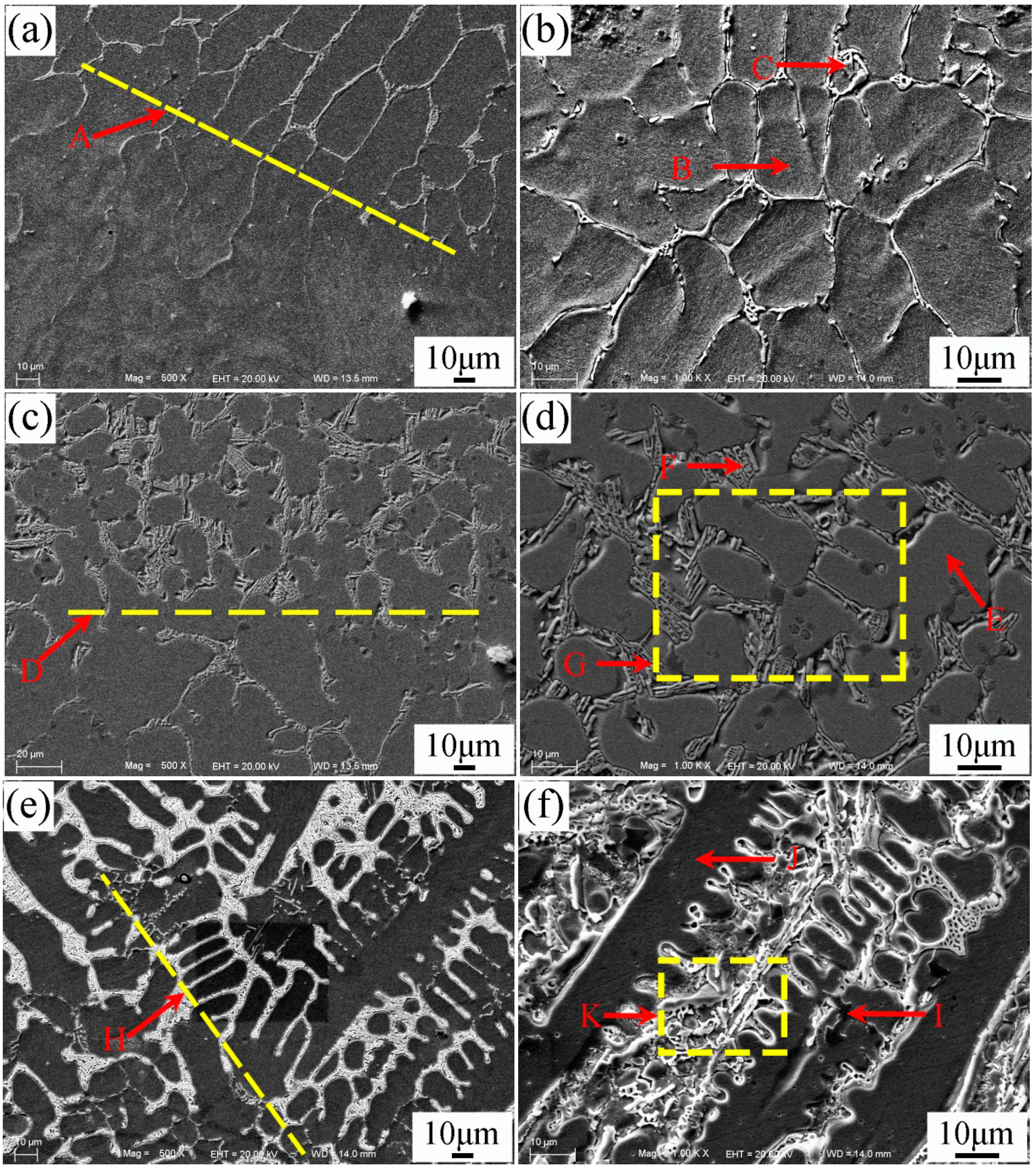
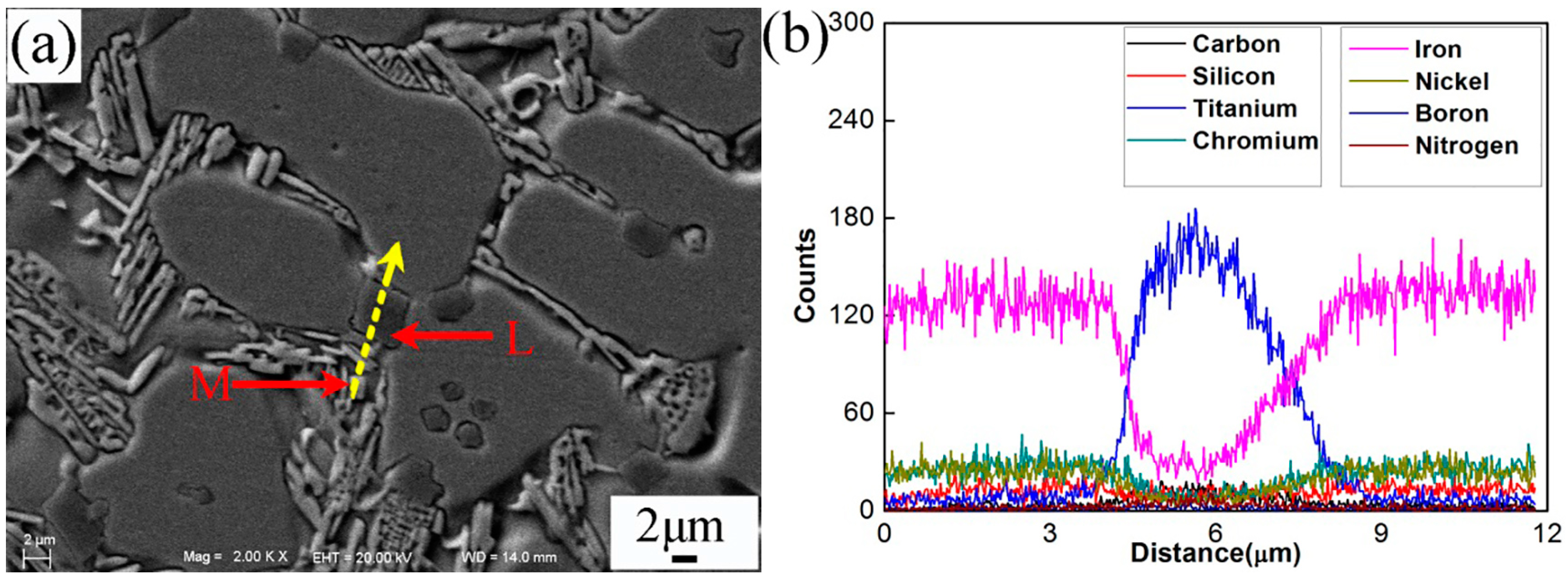
Figure 5a–f shows the SEM morphologies of the interfacial zone between substrate and coating of specimen No.2. The magnification and EDS analysis of locations G and K in
Figure 5 were presented in
Figure 6 and
Figure 7, respectively. The EDS analysis results of
Figure 5,
Figure 6 and
Figure 7 are shown in
Table 6. The yellow line A in
Figure 5a could be seen as the bottom boundary of heat-affected substrate.
Figure 5b shows the morphology of partly melted substrate. Due to the thermal effect of the plasma process, the grains B in this region coarsened. The chemical elements Fe, Cr, Ni, and C were detected in the grain boundary precipitates C, which could be attributed to the diffusion of the elements in the coating. The yellow line D in
Figure 5c can be seen as the boundary between the melted substrate and coating. Adjacent to the line D, cellular grains could be observed as shown in
Figure 5d. The study demonstrated that the content of chemical elements Cr, Mo, V, and C in grain boundary precipitates obviously increased due to the formation of metal carbides. Based on the EDS results, the deep bulk shape microstructure L in
Figure 6 was hard phase TiC. This also indicated that the melted spray welding powders mixed with melted substrate in this area. The yellow line H in
Figure 5e can be seen as the boundary of cellular grains and dendrite grains, as shown in
Figure 5f. According to the analysis results, bulk shape microstructures N and P were (Cr,Fe)
7C
3 and FeNi
3, respectively. The black lump shape titanium carbonitrides I in
Figure 5f was C
1-xN
xTi. Further study had found that there was a large amount of C
1-xN
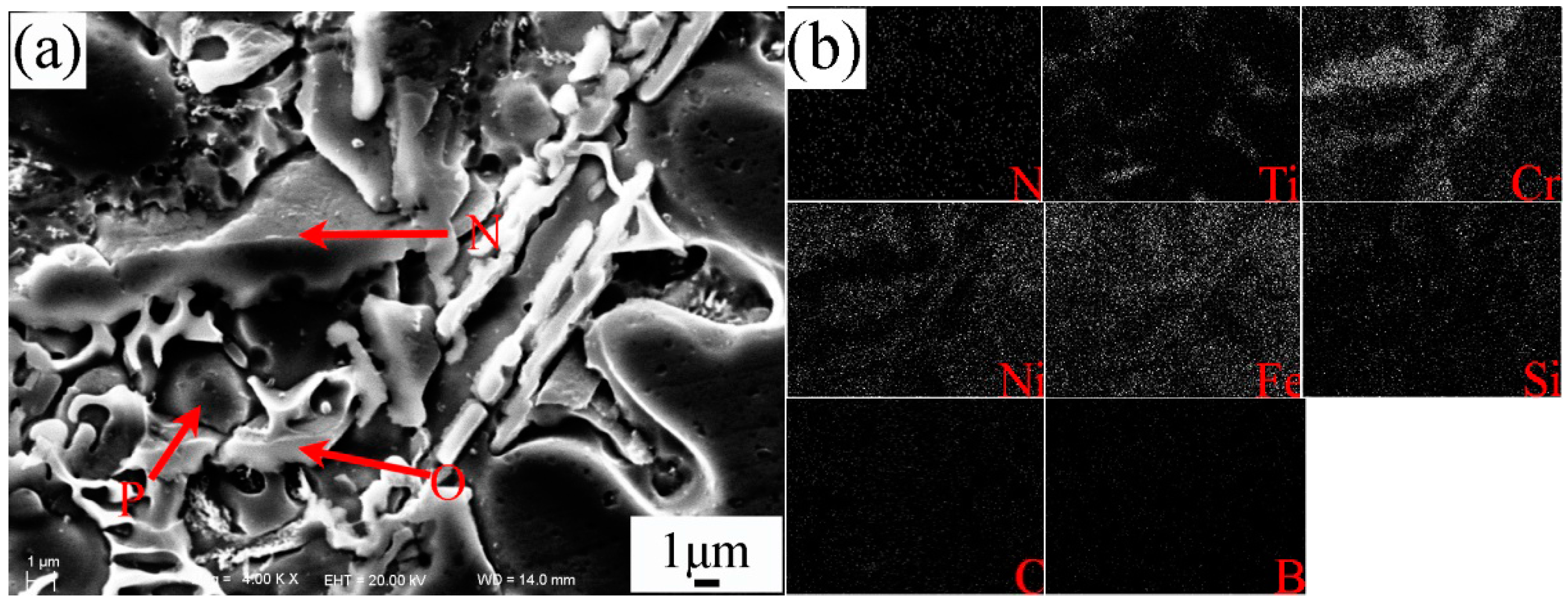
xTi and TiC between the secondary dendrite grains. From the EDS results, the content of Fe in partly melted grains, cellular grains, and dendrite grains gradually decreased, but the content of Cr, Ni, and C gradually increased. This was attributed to the dilution effect weakening of the melted substrate on the coating. The microstructures in yellow line K was presented in
Figure 7. The analysis proved that carbon precipitates N, O, and intermetallic phase P in
Figure 7a were (Cr,Fe)
7C
3, TiC + FeNi
3, and FeNi
3, respectively. Especially, the formation of TiC in the coating greatly improved the hardness and wear resistance of the coating.
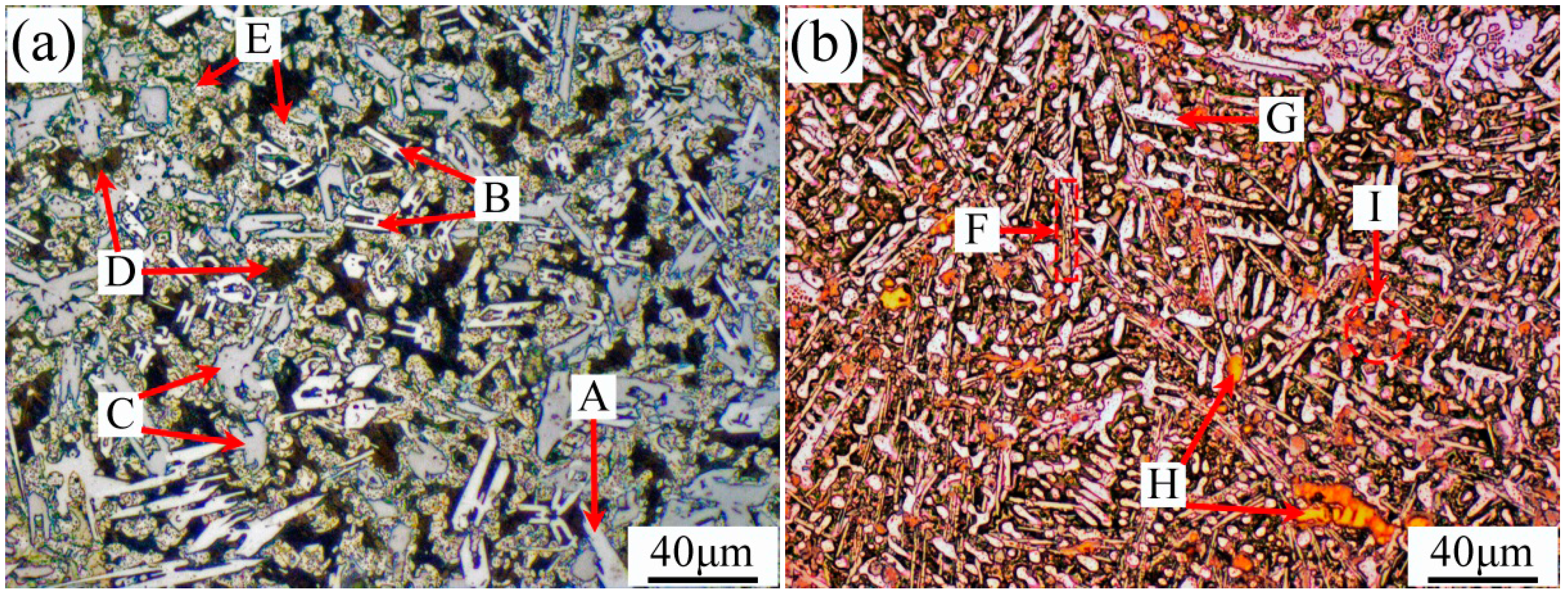
The microstructures of the top coatings of specimens No.1 and No.2 are shown in
Figure 8. Based on the SEM and XRD analyses, it could be concluded that the long white carbon precipitates A and F were (Cr,Fe)
23C
6, “H” shape carbon precipitate B was (Cr,Fe)
7C
3, irregular flake-like carbon precipitate C was Cr
23C
6, and black matrix D was β
1-Ni
3Si + γ-Ni. Further investigation revealed that the clump precipitates of intermetallic phases E and G were FeNi
3, yellow precipitates of nitrides and titanium carbonitrides H and I were TiN and C
1-xN
xTi. Compared with the microstructures of specimen No.1, the microstructures of specimen No.2 were fine due to the generation of the small particles of TiN, C
1-xN
xTi, and TiC from in-situ solid-gas reaction, the size of which usually varied from 10–40 μm.
3.2. The Properties of Plasma Spray Welded Coating
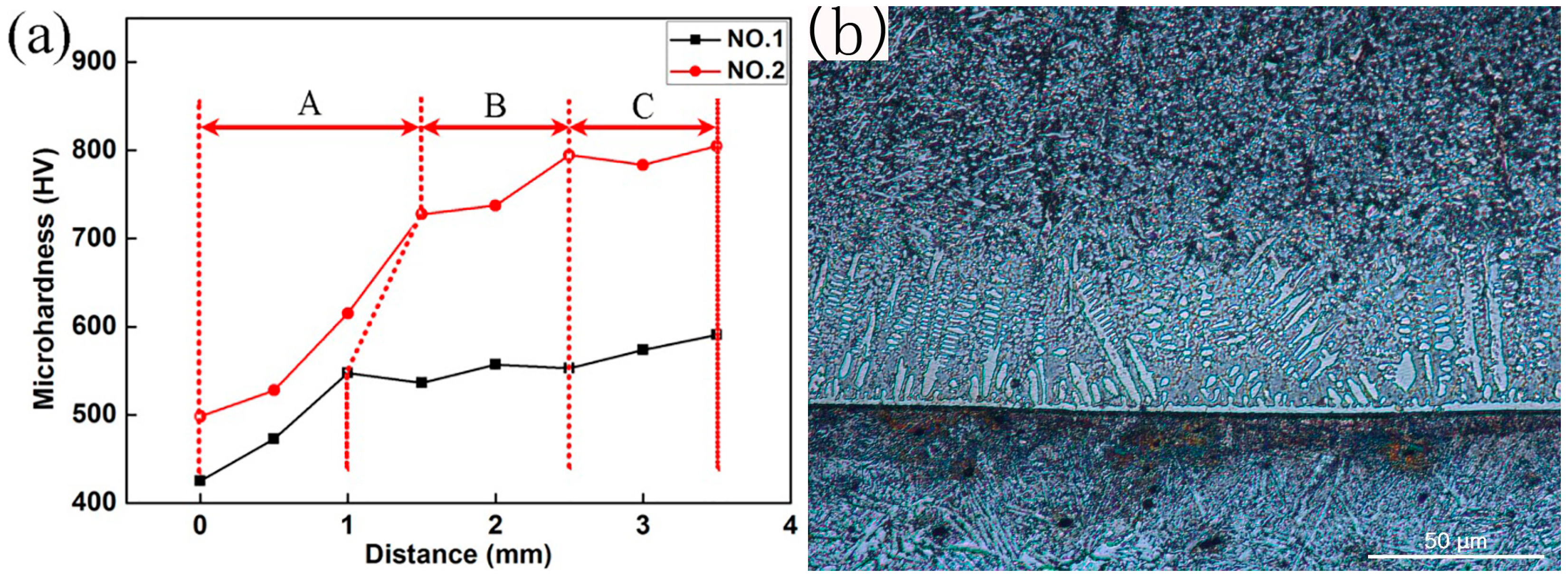
The micro-hardness of the plasma spray welded coating is shown in
Figure 9. The fusion line was taken as the “zero”, and the hardness of the different points from the fusion line to the top of the coating was measured. Generally, the welded coating can be divided into three parts: the bottom A, the middle B, and the top C. From
Figure 9, the bottom A had the lowest hardness, which was mainly attributed to the dilution effect of the substrate material. From the middle part B to the top part C, the hardness of the coating gradually increased because of the rise of the amount of hard phase. The hardness of specimen No.2 was higher than that of specimen No.1, which was attributed to the generation of small particles of TiN, C
1-xN
xTi, and TiC from in-situ solid-gas reaction.
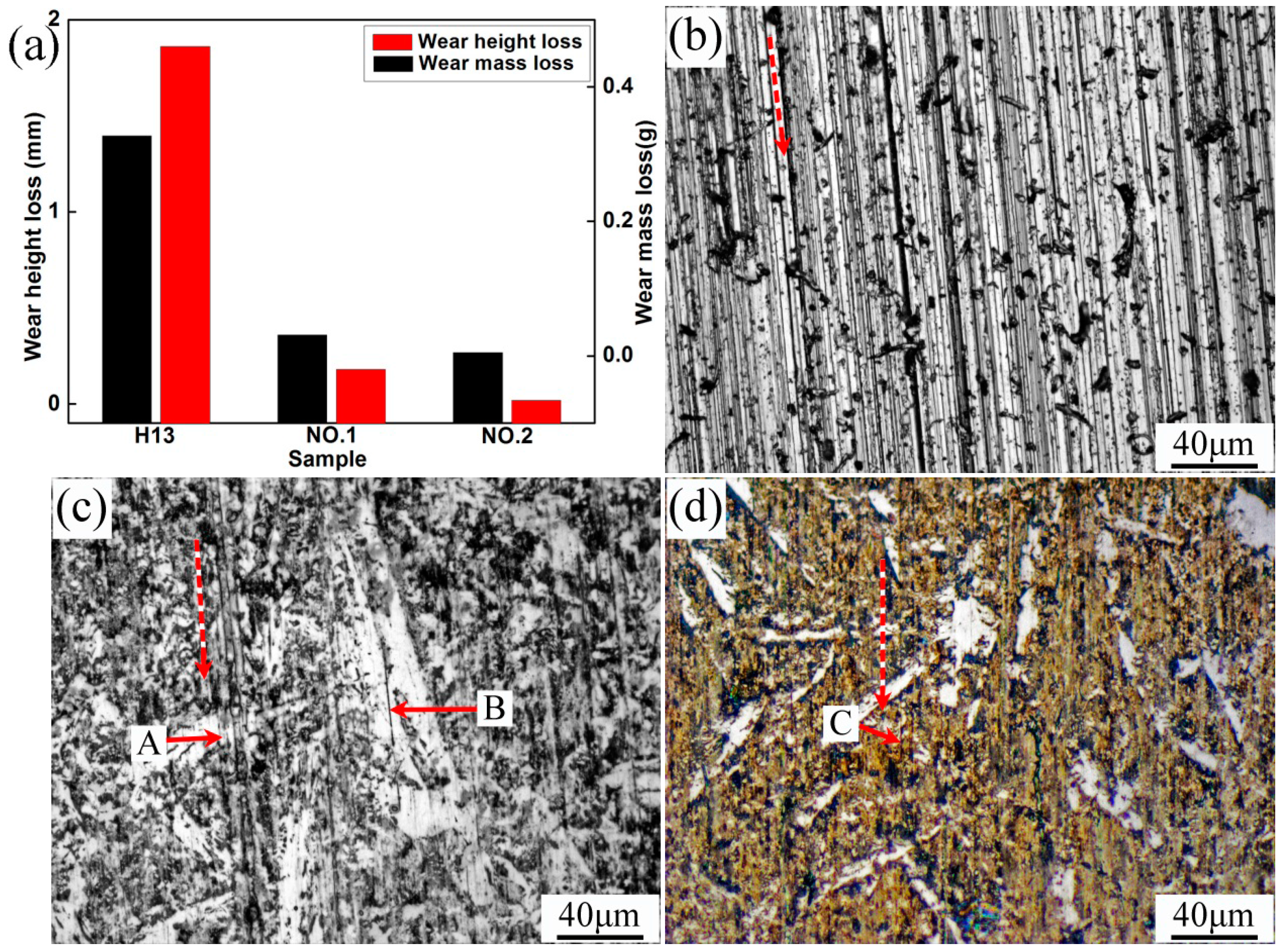
The wear resistance tests for H13, specimens No.1 and No.2 were conducted in this study. The wear resistances of the specimens were evaluated by their height and weight loss before and after tests, as shown in
Figure 10. Obviously, specimen No.2 had the best wear resistance. The surface morphologies of the specimens after test are presented in
Figure 10b–d. The red dashed lines indicate the direction of the wear test. The plowing mark and plastic deformation were deeper and larger in the surface of specimen H13, but shallower and smaller in the surface of specimens No.1 and No.2 after the wear tests. This also conformed to the wear test results. The investigation demonstrated that fine and hard phases TiN and C
1-xN
xTi could effectively alleviate the plowing and cutting behavior.


